Page 310 of 1395
PGM-FI System
(From page 11-107)
Check lor an open in the wirc(SG2line):
Measure voltage between ECM/PCM connector C (31P) terminalsC18 and C28.
Ropair open in th€ wire betweonrhe ECM/PCM (Cl81 .nd the TP56nSOl,
ls there approx. 5 V?
Substitute a known-good ECM/PCM and rocheck. lf pre3cribedvoltago is now avaibble, replacetho origin.l ECM/PCM,
Throttle Position (TP) Sensor (cont'dl
ECM/PCM CONNECTOR C {31PI
Wire side of temale terminals
1 1-108
www.emanualpro.com
Page 312 of 1395

PGM-FI System
Primary Heated Oxygen Sensor (Primary HO2S) (Sensor 1)
The Heated Oxygen Sensors (HO2S) detect the oxygen content in the exhaust gas and signal the ECM/PCM. In operation,
the ECM/PCM receives the signals from the sensor and varies the duration during which fuel is iniected. To stabilize the
sensor's output, the sensor has an internal heater. The Primary HO2S (Sensor 1) is installed in exhaust pipe A.
HO2S:
ztRcoNtAEI.IMENT
s€NsoRTERMINALSVOLTAGE IVI
HEATEBTERMINALS
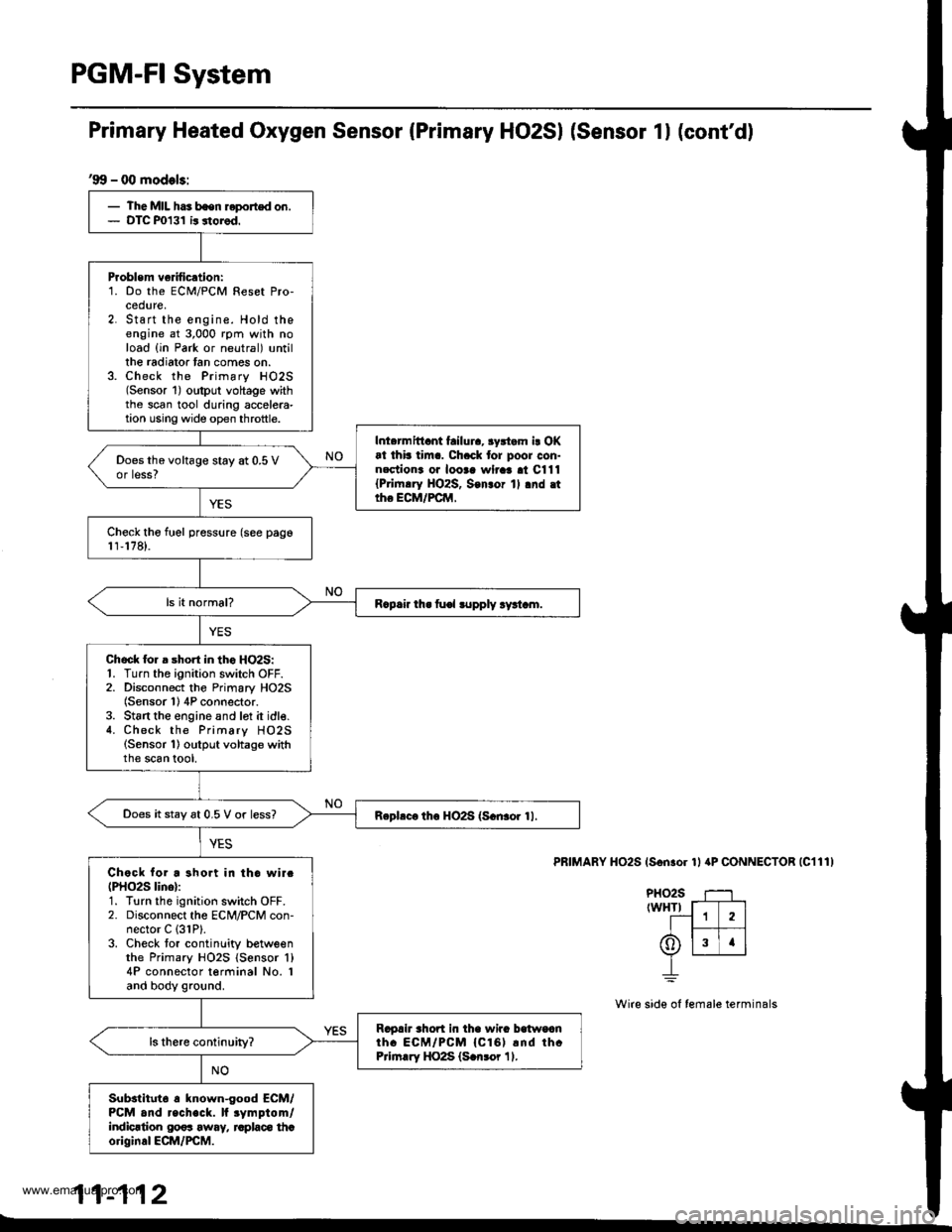
The scan tool indicates Diagnostic Trouble Code (DTC) P0131: A low voltage
Oxygen Sensor (HO2S) {Sensor 1} circuit,
RICH - AIR. . LEANFUELNATO
problem in the Primary Heated
37 - 98 models:
HEATER
The MIL has been reoorted on.DTC P0131 is stoied.
Problem verification:1. Do the ECM/PCM Reset Pro-ceoure.Start the engine. Hold theengine at 3,000 rpm with noload (in Park or neutral) untilthe radiator fan comes on.Test-drive with the A/T in Eposition (M/T in 4th gear)Check the Primary HO2S{Sensor 1} output voltage withthe scan tool during accelera-tion using wide open throttle.
Intermittent f.ilure, system is OKat this time. Check fo. poor con-nections or loose wirer at C111(Primary HO2S, SeGor 1) and atrh€ ECM/FCM.
Check the fuel pressure (see page
11-178).
Repair the fuel supply system.
{To page 11'111}
1 1-1 10
www.emanualpro.com
Page 313 of 1395
{From page 11-110}
Check tor a shorl in the HO2S:1. Turn the ignition switch OFF.2. Disconnect the Primary HO2S(Sensor'1i 4P connector.3. Start the engine and let it idle.4. Check the Primary HO2S(Sensor 1)output voltage withthe scan tool.
Replace the HO2S {Sensor 1).Does it stay at 0.1 V or less?
Check for a short in the wir€(PH02S linel:1. Turn the ignition switch OFF.2. Disconnect the ECM/PCM con-nector (D (16P), C (31P)*).
3. Check tor continuity betweenthe Primary HO2S {Sensor 1)4P connector terminal No. 1and body ground.
Repair short in tho wire botwesnthe ECM/PCM lD7, C16*) .nd th6Prim.ry HO2S (S€nsor 11.
Substituto a known-good ECM/PCM and recheck. ll 3ympiom/indication goes away. raplace th.origin.l ECM/PCM.
PRIMARY HO2S ls.n.or 'l I 4P CONNECTOR (Cl111
PHO2S ---'trwHTr T-T-l
T-1 1 2l
6tlr rlY r___J_J
L
Wire side of temale terminals
(cont'd)
11-111
www.emanualpro.com
Page 314 of 1395

PGM-FI System
'99 - 00 models:
- The MIL has bsen reported on.- DTC P0131 ir storod.
Problem ve fication:1. Do the ECM/PCM Reset Pro-cedure,2. Start the engine. Hold theengine at 3,000 rpm with noload {in Park or neutral) untillhe radiator tan comes on.3. Check the Primary HO2S(Sensor 1) oltput voltage withthe scan tool during accelera-tion using wide op€n throttle.
Inl.rmittant failura, 3yrtam i! OKat thb tim.. Ch.ck tor poor con-nectiona oa looaa wlraa al C111{Pri|n.ry HO2S, Son3or 1l .nd .ttho ECM/FCM,
Does the voltage stay at 0.5 Vor less?
Check tho fuel pressure (see pago1r,178).
R.p.ir th. fu€l lupply ry!t.m.
Chock lor a short in tho HO2S:1. Turn the ignition switch OFF.2. Disconnect the Primary HO2S(Sensor 1) 4P connector.3. St6rt the engine and lot it idle.4. Check the Primary HO2S(Sensor 1) output voltage withthe scan tool,
Does it stay 6t 0.5 V or less?Rephc. th6 HO2S (S.n3or 11.
Chock for a short in tho wirc(PHO2S lino):1. Turn the ignition switch OFF.2. Disconnect the ECM/PCM con-nector C (31P).
3. Check tor continlity betweenthe Primary HO2S {Sensor 'l}
4P connector terminal No. Iand body ground.
Ragah rhort in tha wira balwoanth. ECM/PCM {Cl61 rnd thcPrirn.ry HO2S (S.n3or 11.
Substltut6 a known-good ECM/PCM and recheck. lf rymptom/indicrtion 00os away, raplaco thcoriginal ECM/PCM.
Primary Heated Oxygen Sensor (Primary HO2SI (Sensor 1l (cont'd)
PRIMARY HO2S (Son.or 1l aP CONNECTOR |C111)
PHO2S T--1rwHTr f-T---]
--1 1 2lI t--- 1t6)lslrlv L__r__J
_L
Wire side ol female terminals
11-112
www.emanualpro.com
Page 315 of 1395

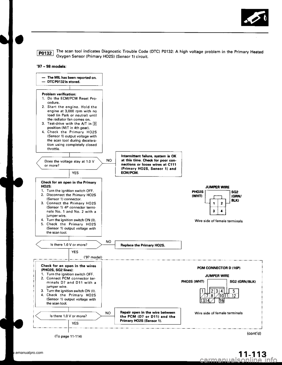
The scan tool indicates Diagnostic Trouble Code (DTC) P0132: A high voltage problem in the Primary HeatedOxygen Sensor {Primary HO2S) (Sensor 1) circuit.
'97 - 98 models:
PHO2S
IWHTIsG2IGRN/BLK}
Wire side ot female terminals
PCM CONNECTOR D {16PI
JUMPER WIRE
PHO2S IWHTISG2 IGRN/BLK}
Wire side of temale terminals
I
(cont'dl
11-113
Problem verification:1. Do the ECM/PCM Resot Pro,ceoute,2. Start the engine. Hold theengine at 3,000 rpm with noload (in Park or neutral) untilthe radiator fan comes on.3. Test-drive with the Ay'T in Eposition (M/T in 4th gear).4. Check the Primary H02S{Sensor 1}output voltage withthe scan tool during decelera-tion using completely closedthrottle.
Intormittent l.ilure, 3ystem ia OKat thb timo. Chcck fo. poor con-nections 01 looso wi.es at C111{Prim!ry HO2S, Sensor 1} andECM/PCM.
Does the voltage stay at 1.0 V
Check for an open in th6 PrimaryH()2S:1. Turn the ignition switch OFF.2. Disconnect the Primary HO2S(Sensor 1) connector-3. Connect the Primary HO25lSensor 1) 4P connector termi-nals No. 1 and No. 2 with ajumper wire.4. Turn the ignition switch ON (ll).5. Check the Primary HO2S(Sensor 1) output voltage withthe scan tool,
ls there 1.0 V or more?
Ch€ck for an opon in the wires(PHO2S, SG2linesl:1. Turn the ignition switch OFF.2. Connect PCM connector ter-minals D7 and Dl1 with a
3. Turn the ignition switch ON (ll).4. Check the Primary HO2S{Sensor 1) output voltage withthe scan tool.
Roprir opon in the wire betweontho PCM {D7 01 D11l and thePrimsry HO2S {S6nsor 1).
ls there 1.0 V or more?
{'97 model}
{To page 11-114)
www.emanualpro.com
Page 316 of 1395
PGM-FI System
Primary Heated Oxygen Sensor lPrimary HO2S) {Sensor 1} {cont'dl
(From page'11-l13)
ECM/PCM CONNECTOR C {31PI
11-114
Ch.ck for an open in the wire(PHO2S linel:1. Turn the ignition switch OFF.2. Connect ECM/PCM connectorterminals C16 and C18 with a
3. Turn the ignition switch ON {ll).4. Check the Primarly H02S(Sensor 1) output voltage withthe scan tool.
R€p.ir open in the wire bqtw€enthe ECM/PCM (C161 and th€Primary HO2S (Sen.or'l).ls there 1,0 V or more?
Substitute a known-good ECM/PCM and rach€ck. lt 3ymptom/indication goos away, replacethe origin.l ECM/PCM.
www.emanualpro.com
Page 317 of 1395

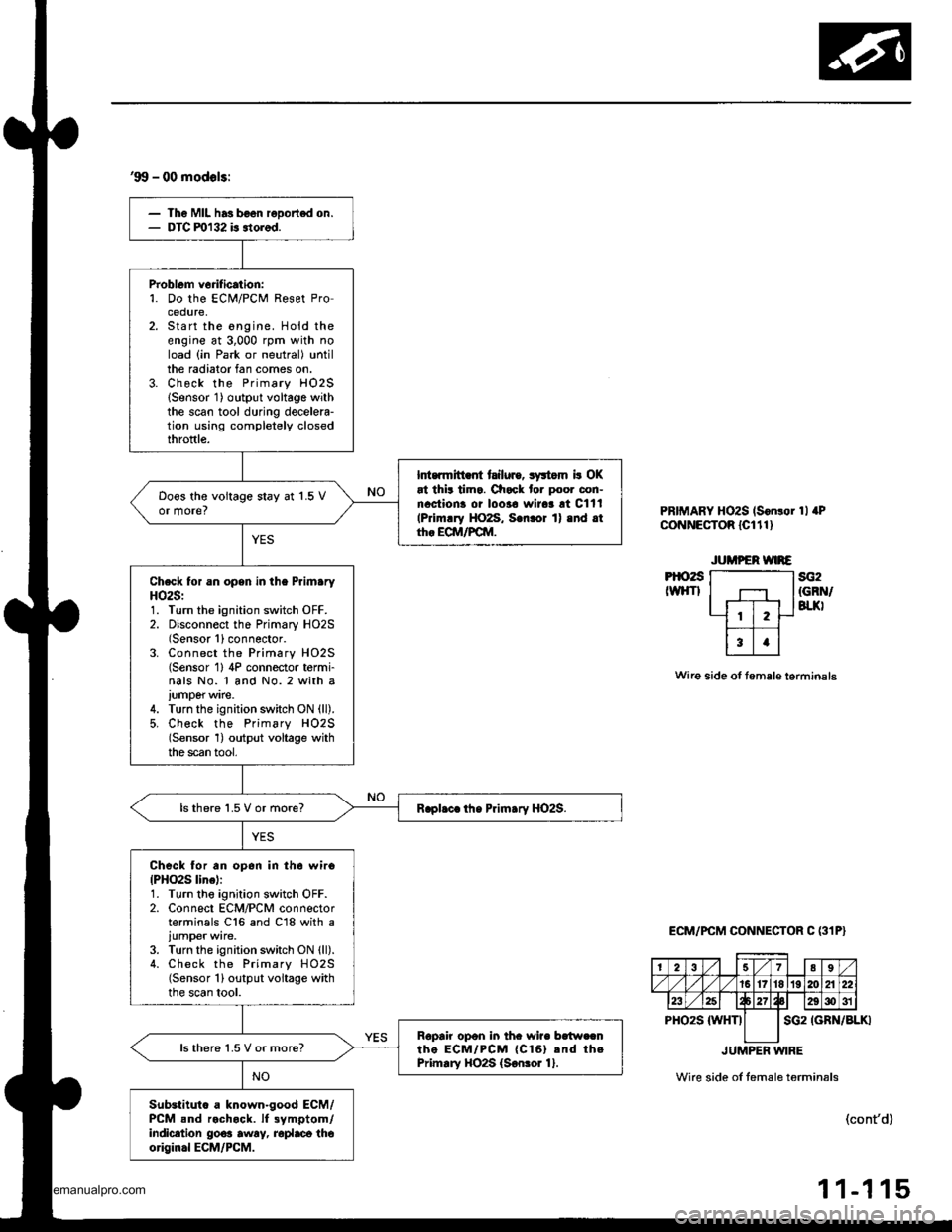
'99 - 00 modols:
Th6 Mll has b€on reDortod on.DTC ml32 is itorod.
Problem vorification:'1. Do the ECi!4/PCM Reset Procedure,Start the ongine. Hold theengine at 3,000 rpm with noload (in Park or neutral) untilthe radiator fan comes on.Check the Primary HO2SlSensor 1) output voltage withthe scan tool during decelela-tion using completely closedthroftle.
Int.rmitt .fi tailuro, syltom b OKat thit tima. Check for poor con-nactiona oi loo3a wirar !t Cltl(Primrry HO2S, S.nror 1) .nd .tth. ECM/FCM.
Doos the voitage stay at 1.5 Vor more?
Check for an opsn in the PrlmaryHO2S:1. Turn the ignition switch OFF.2. Disconnect the Primary HO2S(Sensor 1)connector.3. Connect the Primary HO2S(Sensor 1) 4P connector t6rmi-nals No. 1 and No. 2 with a
iumperwire.4. Turn the ignition switch ON (ll).
5, Check the Primsry H02S(Sensor 1) output voltage withthe scan tool,
lsthere 1.5 V or more?
Check for an op6n in th6 wiro{PHO2S line):1. Turn tho ignition switch OFF.2. Connect ECM/PCM connectorterminals C16 and C18 with a
iumper wire.3. Turn the ignition switch ON lll).4. Check the Primary HO2S(Sensor 1) output voltage withthe scan tool.
Ropair opon in thc wire bc{w.cnthe ECM/PCM {Cl6}.nd thePrimary HO2S {S€nror 1}.ls there 1.5 V or more?
Substituto a known-good ECM/PCM snd rochock. lf 3ymptom/indicetion go€a awry, roplaca thoorigin.l ECM/PCM.
PRIMARY HOzS (S6n!or 1l aPCoNNECTOR lcltl)
Pt()2sIWHTIsG2{GRN/BTJ(I
Wire side of tem6le terminsls
ECM/PCM CONNECTOR C (31P}
IGRN/BLKI
JUMPER WIRE
Wire side ol temale t6rmin6ls
(cont'd)
-1 15
2789
/1617't819120A22
23E29g)31
PHO2S {WHTIsG2
11
www.emanualpro.com
Page 318 of 1395

PGM-FI System
Primary Heated Oxygen Sensor (Primary HO2S) lSensor 1) (cont'd)
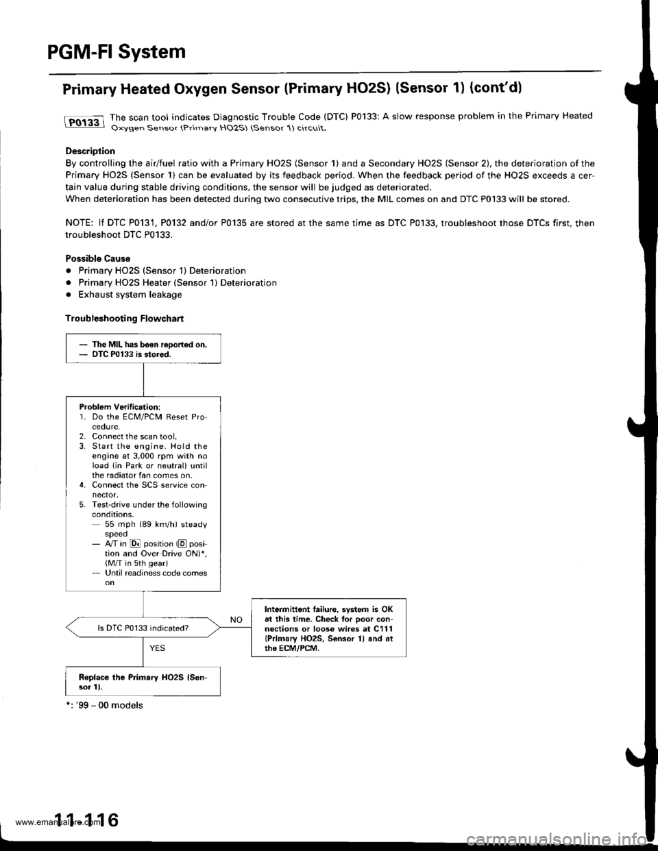
tFO133 lhe scan tool indicates Diagnostic Trouble Code (DTC) P0133: A slow response problem in the Primary Heated: Oxysen Sensor (Primarv HO2S (Sensor 1) circuit.
Description
By controlling the airlfuel ratio with a Primary HO2S (Sensor 1) and a Secondary HO2S (Sensor 2), the deterioration of the
Primary HO2S (Sensor 1) can be evaluated by its feedback period. When the feedback period of the HO2S exceeds a cer
tain value during stable driving conditions, the sensor will be judged as deteriorated.
When deterioration has been detected during two consecutive trips, the MIL comes on and DTC P0133 will be stored.
NOTE: lf DTC P0131, P0132 and/or P0135 are stored at the same time as DTC P0133. troubleshoot those DTCS first, then
troubleshoot DTC P0133.
Possible Cause
. Primary HO2S (Sensor 1) Deterioration
. Primary HO2S Heater (Sensor 1) Deterioration
. Exhaust system leakage
Troubleshooting Flowchart
- The MIL has b6€n reoorted on.- DTC P0133 is stored.
Problem Verilication:'1. Do the ECM/PCM Reset Procedure.2. Connect the scan tool.3. Start the engine. Hold theengine at 3,000 rpm with noload lin Park or neutrali untilthe radiator fan comes on.4. Connect the SCS service connector.5. Test-drive under the followingcondations,55 mph (89 km/h) steadyspeed- M in @ position (E position and Over Drive ON)*,(M/T in sth gear)- Until readiness code comes
Intermittent failure, system is OKat this time. Check tor poor con-nections or loose wires at C111(Primary HO2S, Sensor 1) and althe ECM/PCM.
Replace the Primary HO2S {Sen-sor 11.
1 1-1 16
www.emanualpro.com