1997 HONDA CR-V fluid
[x] Cancel search: fluidPage 818 of 1395

DriveshaftsFront Driveshafts
Inspection
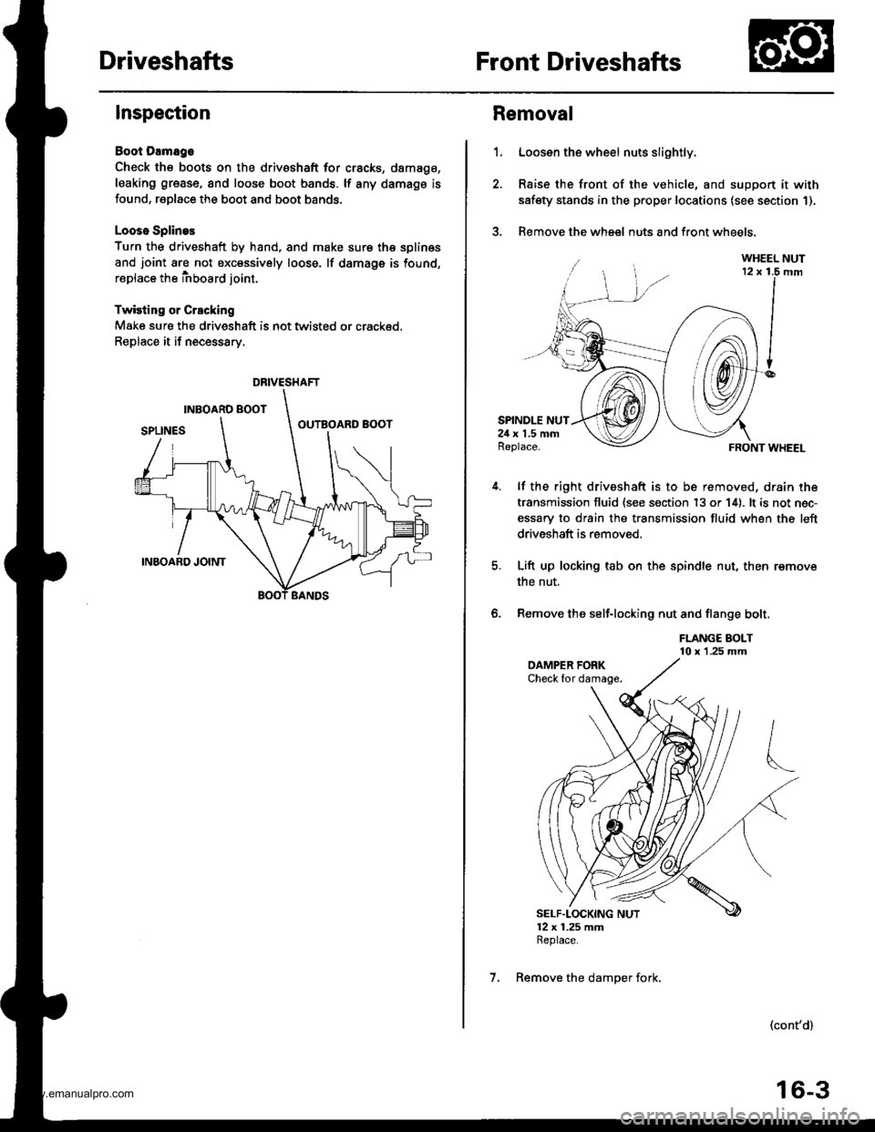
Boot Damago
Check the boots on the driveshaft for cracks, damago,
leaking grease, and loose boot bands. lf any damags is
found, replace the boot and boot bands.
Looso Splines
Turn the driveshaft by hand, and make sure th€ splin€s
and joint are not excessively loose. lf damage is found,
replace the inboard joint.
Twisting or Crscking
Make sure the driveshaft is not twisted or crackod.
Replace it if necessary.
DRIVESHAFT
1.
Removal
Loosen the wheel nuts slightly.
Raise the front of the vehicle, and suppon it with
safety stands in the proper locations (see section 1).
Remove the wheel nuts and front wheels.?
SPINDLE NUT24 x 1.5 mmReplace.
lf the right driveshaft is to be removed, drain the
transmission fluid {see s€ction 13 or 14). lt is not nec-
essary to drain the transmission fluid when the left
driveshaft is removed.
Lift up locking tab on the spindle nut, then remove
the nut,
Remove the self-locking nut and flange bolt,
FLANGE BOLT10 x 1.25 mm
FRONT WHEEL
(cont'd)
6.
SELF"LOCKING NUT12 x 1.25 mmReplace.
7. Remove the damper fork,
16-3
www.emanualpro.com
Page 833 of 1395

Front DriveshaftsIntermediate Shaft
Installation {cont'd}
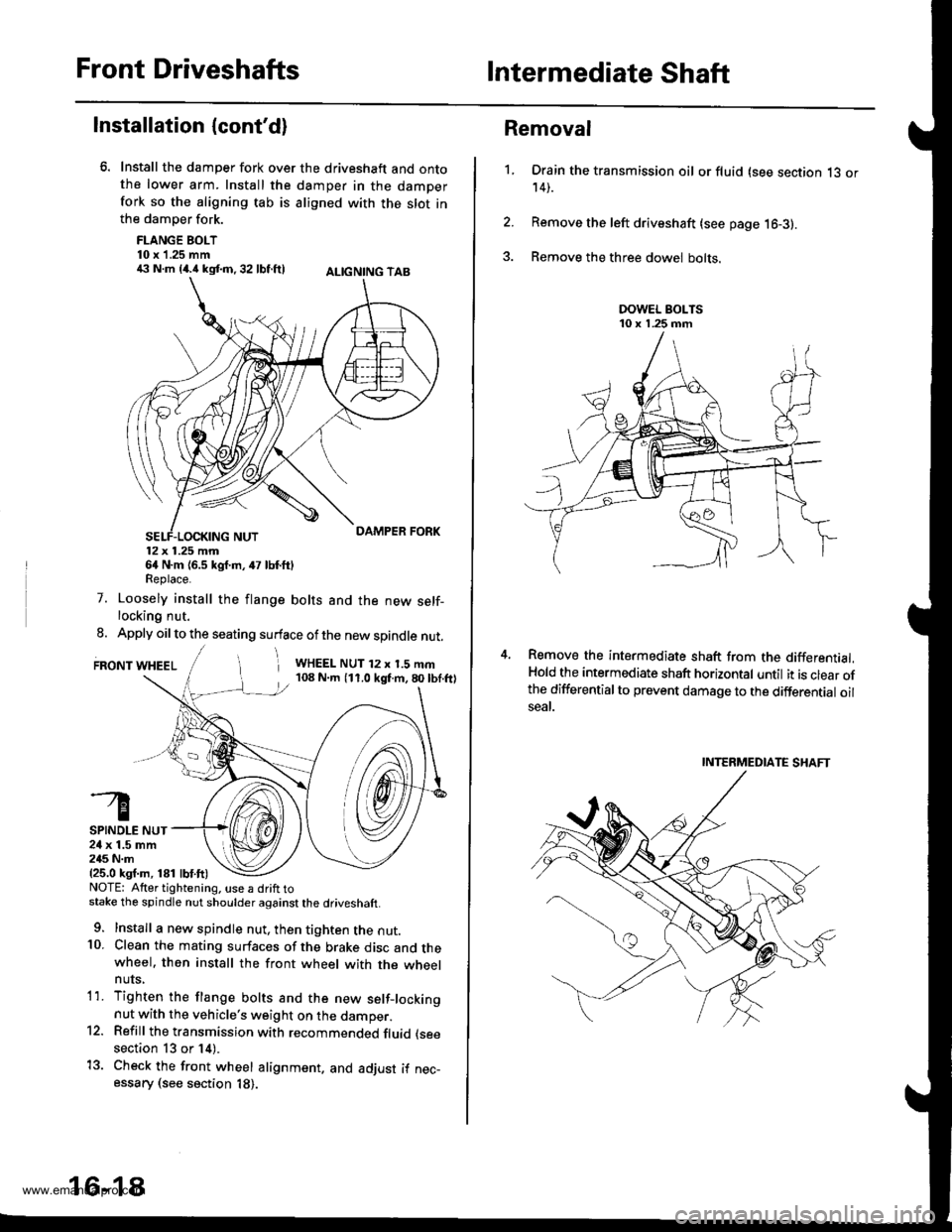
Install the damper fork over the driveshaft and ontothe lower arm. Install the damper in the damperfork so the aligning tab is aligned with the slot inthe damper fork.
FLANGE BOLT10 x 1.25 mm€ N.m {4.i1kst.n,32 lbf.ftl ALtcNtNG TAB
12x 1.25 mm64 N.m {6.5 kgf.m, 47 lbf.ftlReplace.
7. Loosely install the flange bolts and the new self-locking nut.
8. Apply oil to the seating surface of the new spindle nut.
FRONT WHEELi WHEEL NUT 12 x 1.5 mm108 N.m (11.0 kgf.m,80lbf.ftl
SPINDLE NUT24 x 1.5 mm245 N.m{25.0 ksf.m, 181 lbf.ft)NOTE: Atter tightening. use a drift tostake the spindle nut shoulder against the driveshaft.
9. Install a new spindle nut, then tighten the nut.10. Clean the mating surfaces of the brake disc and thewheel. then install the front wheel with the wheelnuts,
1'1. Tighten the flange bolts and the new setf-lockingnut with the vehicle's weight on the damper.12. Refill the transmission with recommended fluid (see
section 13 or 14).
13. Check the front wheel alignment. and adjust if nec-essary (see section 18).
16-18
1.
Removal
Drain the transmission oil or fluid (see section 13 or14).
Remove the left driveshaft (see page 16-3).
Remove the three dowel bolts.
Remove the intermediate shaft from the differential.Hold the intermediate shaft horizontal until it is clear ofthe differentialto prevent damage to the differential oilseal.
INTERMEDIATE SHAFT
www.emanualpro.com
Page 846 of 1395

Steering
Special Toofs ............. 17-2
Component Locations
Index ................ ....... 17-3
Troubleshooting
General Troubleshooting ................ 1 7-4
Noise and Vibration ......................... 17-8
Fluid Leaks ............. 17-10
Inspection and Adiustment
Steering Operation .......................... 17-12
Power Assist Check
With Vehicle Parked ....................
Steering Linkage and Gearbox .......
Pump Belt
Rack Guide Adjustment ...................
Fluid Rep|acement ...................,,.,....
Pump Pressure Check .................,,...
*Steering Wheel
Removal ................. 17-18
*Steering Column
Removal/lnstallation ................ ....... 17 -2O
lnspection .............. 17-21
Steering Lock Replacement ............ 17 -22
Power Steering Hoses, Lines
Ffuid Leakage Inspection ................. 17 -23
Repfacement .......... 17-23
Power Steering Pump
Repfacement .......... 17-24
Disassembly ...........17-25
fnspection .............. 17-26
Reassembly ............ 17-28
Power Steering Gearbox
Removal ................. 17-31
Disassembly ........... 17-34
Reassembly ............ 17-40
Ball Joint Boot Replacement .......... 17-50
Installation ............. 17-51
17-12
17-13
17-14
l7-15
17-15
17-16
Disassembly/Reassembly............... 17-18
4'%/b.......... -r'-7--a/
SUPPLEN\EN AL RES\RA(N SYSTES{ (SRS\
This model has an SRS which includes a driver's airbag in the steering wheel hub. a passenger's airbag in the dashboardabove the glove box ('97 - 00 models), and seat belt tensioners in the seat belt retractors ('98 - 00 models). Informationnecessary to safely service the SRS is included in this Service Manual. ltems marked with an asterisk (*) on the contentspage include, or are located near, SBS components. Servicing. disassembling or replacing these items will require specialprecautions and tools, and should only be done by an authorized Honda oearer.
To avoid rendering the SRS inoperative, which could lead to peFonal iniury or death in the event of a sevore trontalcollision. allSRS service work must be performod by an authorized Honda dealer.lmproper service procedurgs, including incorrect removal and installalion of the SRS, could lead to personal iniurycaused by unintontional deployment of th€ airbags {'97 - 00 models), and seat belt tensioners ('98 - 00 modelsl.Do not bump the SRS unit. Otherwise, the system may lail in case ot a collision, or the airbags may deploy when theignition switch is ON (lll.
SRS electrical wiring harnesses are identitied by yellow colof coding. Ralated components are located in the steeringcolumn, front console, dashboard, dashboard lower panel, and in the dashboard above the glove box. Do not use elec-trical test equipment on these cilcuits,
www.emanualpro.com
Page 848 of 1395

Component Locations
lndex
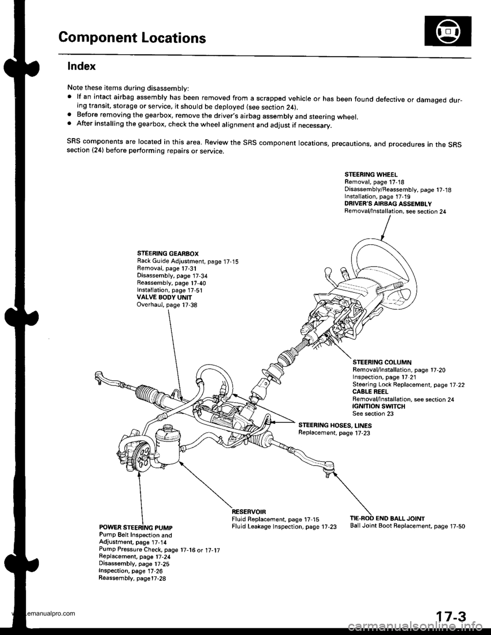
Note these items during disassembly:' lf an intact airbag assembly has been removed from a scrapped vehicle or has been found defective or damaged dur-ing transit, storage or service. it should be deployed (see section 24),a Before removing the gearbox, remove the driver.s airbag assembly and steering wheel.. After installing the gearbox, check the wheel alignment and adjust if necessary.
SRS components are located in this area. Review the SRS component locations, precautions, and procedures an the SRssection (24) before performing repairs or servrce.
STEERING WHEELRemoval, page 17,18Disassembly/Reassembly, page 1?,18Installation, page 17-19DRIVER'S AIRBAG ASSEMBLYRemoval/lnstallation, see section 24
STEERING GEARBOXRack Guide Adjustment, page 17-15Removal, page 17-31Disassembly, page 17-34Reassembly, page 17,40Installation, page 17,51VALVE BODY UNITOverhaul, page 17-38
STEERING COLUMNRemoval/lnstallation. page 17-20Inspection, page l7 21Steering Lock Replacement, page 17 22CABLE REELRemoval/lnstallation, see section 24tcNrnoN swtTcHSee s€ction 23
STEERING HOSES, LINESReplacement. page l7-23
Pump Belt Inspection andAdjustment, pag€ t7-14Pump Pressure Check, page 17-16 ot 17-1jReplacemont, page 17-24Disassembly, pa96 17,25Inspection, page 17-26Reassembly. page17-28
RESERVOIRFluid R6placement. page 17 15Fluid Leakage lnspection, page 17-23
END BALL JOINTBallJoint Boot Replacement, page 17-50
17-3
www.emanualpro.com
Page 849 of 1395

Troubleshooting
General Troubleshootin g
Check the following before you begin:
. Has the suspension been modified in a way that would affect steering?
. Are tire sizes, tire variety and air pressure correct?
. ls the steering wheel original equipment or equivalent?
. ls the power steering pump belt properly adjusted?
. ls steering fluid reservoir filled to proper level?
. ls the engine idle speed correct and steady?
Hard Steering (Check the power assist, see page 17-12. lf the force is over 29 N (3.0 kgl 6.6 lbfl, proceed with this troubleshooting.i
Abnormalthiidpressure (Iluidpressure is toohigh)
Relief pressuretoo low
Faulty valve body unit
Abnormal
Check the teed and return circuit lines and hosebetween the gearbox and pump for clogging anddeformation.
Normal line and hose
Check the pump fluid pressure(see page 17-16 or 17-17).Measure steady state lluid pres-
sure at idle with the pressure con-trol valve and the shut-off valve (it
so equipped) fully open.The fluid pressure should be 1,500kPa (15 kgf/cm,,213 psi)or less.
Normal
Check the flow control valve (see page 17 26).. Check the valv€ lor smooth movement in the hous-ing.. Check the relief valve for leaks.
Check the pump fluid pressure(see page 17-16 or l7-17).Measure pump relief pressure atidle with the pressure controlvalve and the shut'off valve lil soequipped) fully closed.The fluid pressure should be 6,9007,800 kPa (70 - 80 kgflcm,, 1,000- 1,140 psi).
Normal relief pressure
17-4
Go to page 17 5Faulty pump assemblyFaulty flow control valve
www.emanualpro.com
Page 852 of 1395

Uneven or rough steering.Ad,ust the rack gu ide (see page 17- 15).
ll the problem is not corrected byadjusting the rack guide, replacethe gearbox.
Adjust the belttension. Replace thebelt, if necessary (see page 17-14).Belt slipping on pulley.
lf the engine stalls when thewheel is turned while the vehicleis stopped or moving at lowspeed, adjust the idle speed (seesection 111.
ldle speed low or erratic.
Check power steering lluid level. lfthe level is excessively low checkfor leaks in the system. Add fluidto the specified level.
Air in reservoir, or check powersteering tluid level.
lf fluid level is OK, check O-ringsand seals on both ends of thepump inlet hose, and the P/Spump housing mating surlacesand drive shaft oil seal for suction leaks. Check the reservoir forcracks, Replace parts as neces-
Pump belt slipping on pulley(pump stops momentarily).Adjust the belt tension (see page17-14) or replace belt.
Check if pump pressure is normaland the gauge needle travel is 500kPa (5 kgl/cm,, 71 psi) or less.Check the flow control valve if theneedle travel exceeds 500 kPa (5kgflcm'�, 71 psi). lI the flow controlvalve is normal, replace the pumpas an assembly,
Install the power steering pres-sure gauge, Close the pressurecontrol valve and shut off valve (if
so equipped) fully and measurethe pump pressure (see page 17-16ot 17 17).
Steering wheel kicks backduring wide turns.
7-7
www.emanualpro.com
Page 853 of 1395

Troubleshooting
Noise and Vibration
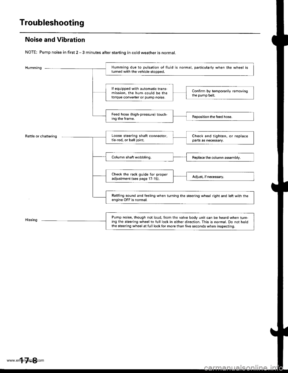
NOTE: Pump noise in first 2 - 3 minutes after starting in cold weather is normal.
Humming
Rattle or chattering
Humming due to pulsation of fluid is normal, particularly when the wheel isturned with the vehicle stooDed.
lf equipped with automatic trans-mission, the hum could be thetorque converter or pump noase.
Confirm by temporarily removingthe pump belt.
Feed hose (high-pressure) touch-ing the frame.Beposition the feed hose.
Loose steering shaft connector,tie-rod, or balljoint.Check and tighten, or replaceparts as necessary,
Column shaft wobbling.Roplace the column assembly.
Check the rack guide for properadjustment (see page 17-15).Adjust, if necessary.
Rattling sound and feeling when turning the steering wheel right and left with th€engine OFF is normal.
Pump noise, though not loud, from the valve body unit can be heard when turn-ing the steering wheel to full lock in either direction. This is normal. Do not holdthe steering wheel at full lock lor more than five seconds when inspecting.
17-8
www.emanualpro.com
Page 854 of 1395

Pump noiseGrating nois€trom pump
Pump noise
Raftle or chattering
Check the fluid lev€1.lt low, fill the reservoir to theproper level. and check for leaks.Tighten or roplace as necessary,
Cavitation caused by air bubblesin the fluid.
Check for a crushed inlet hose ora loose hose clamp allowing airinto the suction side of the system. Check the reservoir forcracks. Tighten or replace as nec-
Check the drive shaft oil seal.
Pump noise up to 2 - 3 minutesafter starting in cold weather isnormal, Compare pump noise atoperatrng temperature to anothervehicle.
ll pump noise is abnormally loud,remove and inspect the pump forwear and damage (see page 17-251.
Tighten or replace the pulley.lI shaft is loose, replace thepump.
17-9
www.emanualpro.com