Page 365 of 1395
{From page 11 162)
PCM CONNECTORS
Wire side of female terminals
c t3lPl
Check for a short in the PSP
swilch:1. Turn the ignition switch OFF.2. Disconnect the 2P connectorfrom the PSP switch.3. Turn the ignition switch ON (ll).
4. lleas u re voltage betweenPCM connector terminals C16and A9.
Check tor a short in the wire (PSP
SW linol:1. Turn the ignition switch OFF.2. Disconnect PCM connector C(31P).
3. Check for continuity betweenbody ground and PCM connec-tor terminal C16.
Reoair short in the wire betwoonrhe PCM {C16) and the PSP3witch.
Substitute a known-good PCM
and rocheck. lf proscribod volt-age b now available, replace theoriginal PCM.
(cont'd)
-16311
www.emanualpro.com
Page 367 of 1395
{From page 11 164i
Check for a short in the PSPswitch:1. Turn the ignition switch OFF.2, Disconnect the 2P connectorfrom the PSP switch.3. Turn the ignition switch ON (ll).
4. Measure voltage betlveen ECM/PCM connector terminals A26and 820.
Check lor e 3hort in the wire IPSPSW linell1. Turn the ignition switch OFF.2. Disconnect ECM/PCM con-nector A (32P).
3. Check for continuity betweenbody ground and ECM/PCMconnector terminal A26.
ReDair short in the wir€ bstweenthe ECM/PCM (A26) and the PSPswitch.
Substitute a known-good ECM/PCM and rechock. It Drescribodvoltago is now available, roplacethe origin.l ECM/PCM,
ECM/PCM CONNECTORS
A l32Pl
Wire side of female terminals
Wire side of female terminals
1 1-165
www.emanualpro.com
Page 370 of 1395

ldle Control System
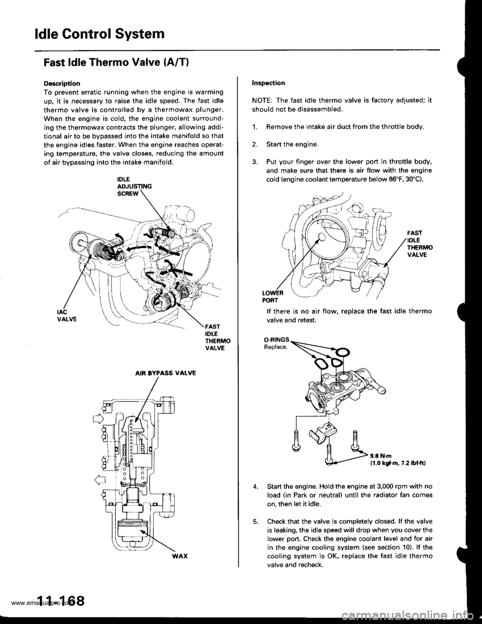
Fast ldle Thermo Valve lA/T)
Description
To prevent erratic running when the engine is warming
up, it is necessary to raise the idle speed. The fast idle
thermo valve is controlled by a thermowax plunger.
When the engine is cold, the engine coolant surround-
ing the thermowax contracts the plunger, allowing addi-
tional air to be bvDassed into the intake manifold so that
the engine idles faster. When the engine reaches operat-
ing temperature. the valve closes, reducing the amount
of air bypassing into the intake manifold.
IDLEADJUSTING
IDLETHERMOVALVE
AIR BYPASS VALVE
11-168
Inspgction
NOTE: The fast idle thermo valve is factory adjusted; it
should not be disassembled.
1. Remove the intake air duct from the throttle body.
2. Start the engine,
3. Put your finger over the lower port in throttle body,
and make sure that there is air flow with the engine
cold (engine coolant temperature below 86"F, 30'C).
lf there is no air flow, replace the fast idle thermo
valve and retest,
O-RINGSReplace.
11.0 kgfl.m, 7.2 lbl.ftl
Start the engine. Hold the engine at 3,000 rpm with no
load (in Park or neutral) until the radiator fan comes
on, then let it idle.
Check that the valve is completely closed. lf the valve
is leaking, the idle speed will drop when you cover the
lower pon. Check the engine coolant level and for air
in the engine cooling system {see section 10). lf the
cooling system is OK, replace the fast idle thermo
valve and recheck.
www.emanualpro.com
Page 385 of 1395

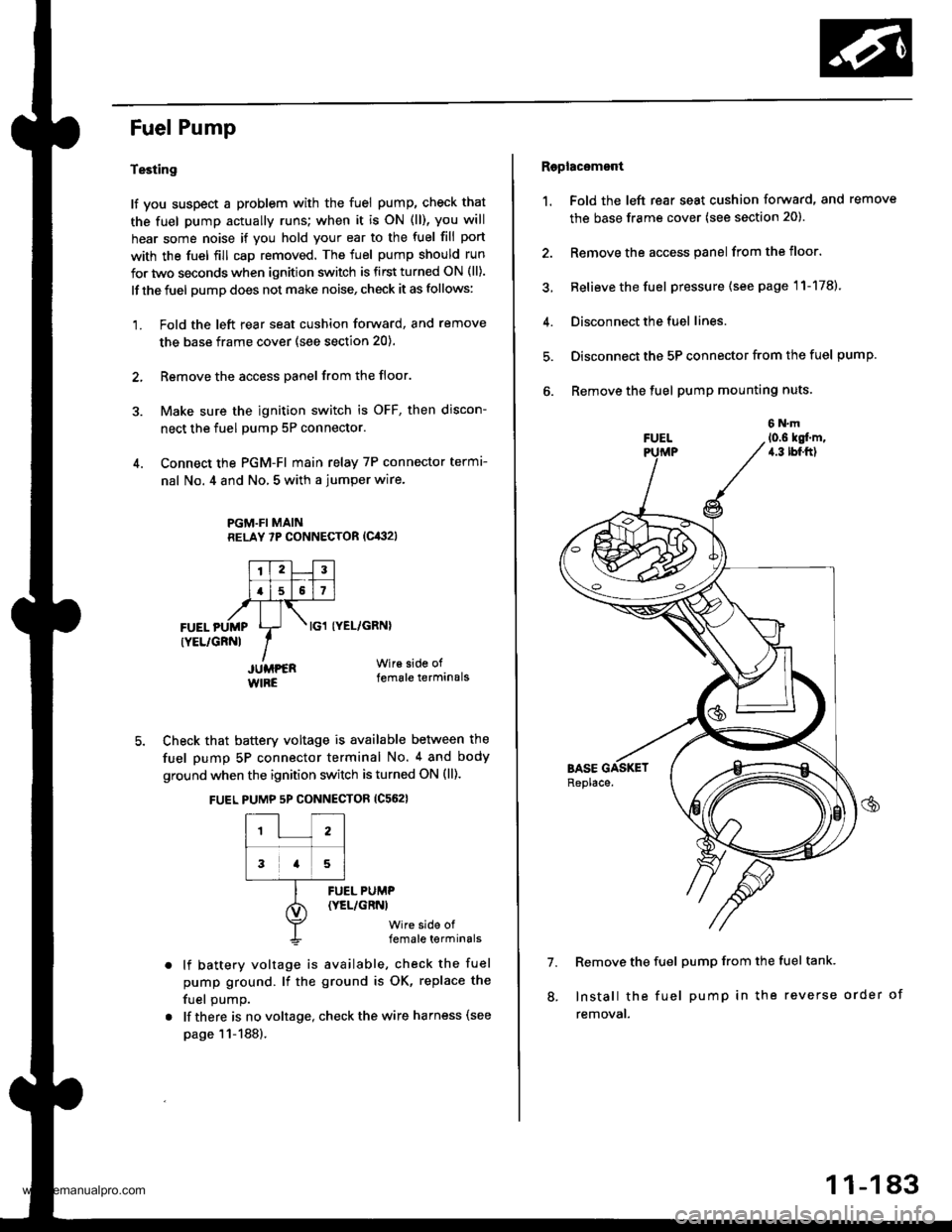
Fuel Pump
Testing
lf you suspect a problem with the fuel pump, check that
the fuel pump actually runs; when it is oN (ll), you will
hear some noise if you hold your ear to the fuel fill port
with the fuel fill cap removed. The fuel pump should run
for two seconds when ignition switch is first turned ON (ll).
lf the fuel pump does not make noise, check it as follows:
1. Fold the left rear seat cushion forward, and remove
the base frame cover (see section 20).
2, Remove the access panel from the floor.
3. Make sure the ignition switch is OFF, then discon-
nect the fuel pumP 5P connector.
4. Connect the PGM-FI main relay 7P connector termr-
nal No. 4 and No, 5 with a jumper wire.
PGM.FI MAINRELAY 7P CONNECTOR (Cit:}2l
I'TtlJilt f -r'-r ll.l5l517l,frTt-,at\FUEL pUMp Lr- . tcl tyEL/cRNl
rYEL/cRNl IIJUMPER Wir€ side of
WIRE female terminals
5. Check that battery voltage is available between the
fuel pump 5P connector terminal No. 4 and body
ground when the ignition switch is turned ON (ll).
FUEL PUMP 5P CONNECTOR {C562}
12
3a5
lf battery voltage is available, check the fuel
pump ground. lf the ground is OK, replace the
fuel oumo.
lf there is no voltage, check the wire harness (see
page 11-188).
FUEL PUMP(YEL/GRNI
wire side offemale terminals
Raplac6mont
1. Fold the left rear seat cushion forward, and remove
the base frame cover (see section 20).
2. Remove the access panel from the floor.
3, Relieve the fuel pressure (see page 11-178).
4. Disconnect the fuel lines.
5. Disconnect the 5P connector from the fuel pump.
6. Remove the fuel pump mounting nuts.
7. Remove the fuel pump from the fuel tank.
Install the fuel pump in the reverse order of
removal.
8.
11-183
www.emanualpro.com
Page 390 of 1395
![HONDA CR-V 1997 RD1-RD3 / 1.G Workshop Manual
Fuel Supply System
PGM-FI Main Relay (contdl
Troubleshooting
lc(}21PGM.FI MAIN RELAY 7P CONNECTOR
GND
trTr]--Flq
FI,TilI A
Y
Wire side ot female terminals
- Engine will not start.- InsDection ol PG HONDA CR-V 1997 RD1-RD3 / 1.G Workshop Manual
Fuel Supply System
PGM-FI Main Relay (contdl
Troubleshooting
lc(}21PGM.FI MAIN RELAY 7P CONNECTOR
GND
trTr]--Flq
FI,TilI A
Y
Wire side ot female terminals
- Engine will not start.- InsDection ol PG](/manual-img/13/5778/w960_5778-389.png)
Fuel Supply System
PGM-FI Main Relay (cont'dl
Troubleshooting
lc(}21PGM.FI MAIN RELAY 7P CONNECTOR
GND
trTr]--Flq
FI,Til'I A
Y
Wire side ot female terminals
- Engine will not start.- InsDection ol PGM-FI mainrelay and relay harness,
Check fo. an open in the wireIGND linol:1. Turn the ignition switch OFF.2. Disconnect the PGM Fl mainrelay 7P connector.3. Check for continuity betweenthe PGM'FI main relay 7P con-nector terminal No. 3 and bodyground.
Repair opcn in th€ wire betweenthe PGM-FI main relav and G101.
Check tor an open or short in thewiro (BAT line):Measure voltage between thePGM'FI main relay 7P connectorterminal No. 7 and body ground.- Repai. open or short in lhewir6 belween the PGM-FImain relay and the Fl E/M (15Al fu3e.- Replace th6 FIE/M (15 Altus6in th€ under-hood fuse/.6lay
ls there baftery voltage?
Check lor an open or short in thewire (lGl line):L Turn the ignition switch ON (ll).2. Measure the voltage betweenthe PGM-FI main relay 7P connectorterminal No. 5 and bodyground.- Repair open or shorl in thewire between the FGM-FI mainrelay and the No. 13 FUELPUMP 115 A) tuse.- Replaco the No. 13 RJEL PUMP115 A) luse in the und6.-d$hfuso/ relav box.Check for an open or short in thewire {STS line):1. Turn the ignition switch to theSTART (lll) position.NOTE:. M/T: Clutch pedal must bedepressed.. A/T: Transmission in E orElposition.2. Measure the voltage betweenthe PGM-Fl main retay 7Pconnector terminal No. 2 andbody ground.- Repair open or short in thewire betwe€n the PIGM-FI m.inrclay and th€ No. 31 STARTERSlGllAL 17.5 A) tuse.- Repl.ce the No. 31 STARTERSIGNAL 17.5 Al tuse in theunder-dash tuse/relay box.('97 model: To page 11-189)('98 00models:To page 1l 190)
1 1-188
www.emanualpro.com
Page 395 of 1395
Intake Air System
System Description
The system supplies air for all engine needs. lt consists of the intake air pipe, Air Cleaner, intake air duct, Throttle Body
(TB), ldle Air Control (lAC) Valve, fast idle thermo valve, and intake manifold. A resonator in the intake air pipe provides
additional silencing as air is drawn into the system.
INTAKE MANIFOLD
YEL| - - Fiom PGM'FI
BLK T MAIN RELAY
IDLETHERMO
lJ- _iuo'u'j"'
INTAKEAIR DUCT
vaRtousSENSORS
FESONATON
THROTTLEBODY (TB)
1 1-193
www.emanualpro.com
Page 398 of 1395
Intake Air System
Throttle Body
Doscription
The throttle body is a single-barrel side-draft type. The
lower portion of the throttle valve is heated by engine
coolant from the cylinder head. The idle adjusting screw
which regulates the bypass air is located on the top of
the throttle bodv.
The illustration shows'97 - 98 models,'99 - 00 rnodelsare similar.
1 1-196
lnspection
Check that the throttle cable operates smoothly without
binding or sticking.
lf there are any abnormalities, check for:. Excessive wear or play in the throftle valve shaft.. Sticky or binding throttle lever at the fully closed posi-
tton.
. Clearance between throttle stop screw and throttle
lever at the fully closed position.
97 - 98 models:
THROTTLE LINKAGE
Replace the throttle body if there is excessive play in the
throttle valve shaft or if the shaft is binding or sticking.
THROTTLE LINKAGE
www.emanualpro.com
Page 400 of 1395
Intake Air System
Throttle Body (cont'd)
Disassembly
O-RING {A/l only)Replace.
IDLE THERMOVALVE (A/T only)
ADJUSTINGSCREW
9.8 N.m(1.0 kgl.m,7.2 lbf.ftl
The illustration shows'97 - 98models,'99 00 models are similar.
1 1-198
www.emanualpro.com