Page 1003 of 1395

Doors
Front and Rear Door Glass
Adiustment (cont'dl
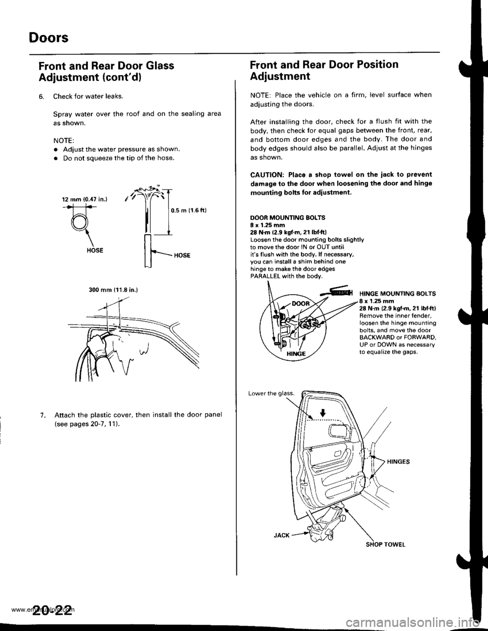
6. Check for water leaks.
Spray water over the roof and on the sealing area
as snown.
NOTE:
. Adjust the water pressure as shown.
. Do not soueeze the tio of the hose.
12 mm {0.47 in.l
#
(r\"1
HOSE
-"'*r"i
,'r)"f
tl
0.5 m (1.6 ftl
7. Attach the plastic cover, then install the door panel
(see pages 20-7, 'l 1),
20-22
..-
300 mm 111.8 in.)
Front and Rear Door Position
Adjustment
NOTE: Place the vehicle on a firm, level surface when
adiusting the doors.
After instailing the door, check for a flush fit with the
body, then check lor equal gaps between the front, rear.
and bottom door edges and the body. The door and
body edges should also be parallel. Adjust at the hinges
as shown.
CAUTION: Placa a shop towel on the iack to prevent
damage to the door when loosening the door and hinge
mounting bolts lor adiustment.
DOOR MOUNTING BOLTSI x 1.25 mm28 N.m 12.9 kgtr.m, 21 lbI.ftlLoosen the door mounting bolrs slighrlyto movethe door lN or OUT untilit's flush with the bodv. lf necessary,you can installa shim behind onehinge to make the door edgesPARALLEL with the bodv.
HINGE MOUNTING BOLTS8 x 1.25 mm28 N,m 12.9 kgt.m. 21 lbl.ftlRemove the inner fender,loosen the hinge mountingbolts, and move the doorBACKWARD or FORWARD,UP or DOWN as necessaryto equalize the gaps.
Lower the glass.
www.emanualpro.com
Page 1004 of 1395
The door and body edges should be parallel. lf neces-
sary, adjust the door cushion.
ry.DOOR CUSHION
Check for water leaks.
NOTE: Do not squeeze the tip ofthe hose.
oooR cusHroNs
Tailgate Door Position Adjustment
NOTE: Place the vehicle on a firm, level surface when
adjusting the tailgate door.
After installing the tailgate door. check for a flush fit
with the body, then check for equal gaps between the
tailgate door edges and the body. The tailgate door and
body edges should also be parallel. Adjust at the hinges
as snown.
CAUTION: Place a shop towel on the iack lo prevent
damage to the tailgale door when loos€ning the tail-
gate door and hinge mounting bolts for adiustment.
TAILGATEDOORMOUNTING sOLTS8 x 1.25 mm25 N.m {2.6 kgf.m,19 tbf.ft)
HINGE MOUNYINGBOLTS8 x 1.25 mm25 N.m 12.6 kgt m,19 rbf.ftl
8x1.0mm22 N'rrl� 12.2 kgl.m,16 tbt.ftl
6xl.0mm9.8 N.m {1.0 kgt m,1.2 tbl.ltl
(cont'd)
20-23
www.emanualpro.com
Page 1008 of 1395
Power Mirror Replacement
NOTE: Tako care not to scratch the mirror, mirror mount
cover and door.
1. Lower the door glass fully.
2. Carefully pry out the mirror mount cover by hand,
,l
Disconnect the connector. then remove the mirror
mounting bolts while supponing the mirror,
>: Boh locations, 3
Installation is the reverse of the removal procedure,
NOTE: Make sure the connector is connected prop-
efly.
HOOK
MIRROR
Power Mirror Holder Replacement
CAUTION: Put on glovss to protest you. hands.
NOTE: Take care not to scratch the mirror.
1, Carefully pull out the bottom edge of the mirror
holder bv hand.
Separate the mirror holder from the actuator bv
slowly pulling them apart.
Reattach the hooks of the mirror holder to the actu-
ator, then Dosition the mirror holder on the actua-
tor. Carefully push the clip portions of the mirror
holder untilthe mirror holder locks into place.
Check the actuator ooeration.
ADHESIVE
20-27
www.emanualpro.com
Page 1058 of 1395
Front Grille
Replacement
CAUTION: When prying with a flat-tip screwdriver,
wrap it with protective tape, and apply protective tape
around the related parts to prevent damage.
NOTE: Take care not to scratch the front orille and front
oumper.
1. Remove the front grille emblem cover. Loosen and
remove the grille mounting screws. and remove the
front grille by pulling it forward.
>: Screw locationsa>,5s>,2
@-l @,"l
NOTE: Insert a Phillips screwdriver through theholes in the front grille, then loosen the screws.
2. Installation is the reverse of the removal procedure.
20-77
www.emanualpro.com
Page 1062 of 1395
Adjustment
NOTE:
. After adjusting the tailgate door, adjust the rear hatch glass.
. Loosen the striker mounting bolts slightly.
. Remove the rear spoiler, and remove the support strut from body side.
1. Loosen the rear hatch glass mounting nuts.
2. Adjust the rear hatch glass so there are equal gaps between the rear hatch glass, the taillights, and the tailgate door.
NOTE: lf necessary, loosen the rear hatch glass hinge mounting nuts and move the rear hatch glass backward or for-
ward to fit the rear weatherstrip and tailgate door weatherstrip.
REAR HATCI{GLASS HINGES
REAR HATCH GLASS HINGEMOUNTING NUT6x1.0mm9.8 N.m (1.0 kgf.m,7.2 tbt f Remove the rear edgeotthe headliner(see page 20-44).
MOUNTING NUT6x1.0mm9.8 N.m 11.0 kgtm,7.2 rbf.ftt
Taillight side:Tailgate door side:
About7mm
1o.27 in.l
NOTE: Adjust for equal gapsbetween the right and left.TCH GLASSIHAREAR
(cont'd)
20-81
www.emanualpro.com
Page 1063 of 1395

Rear Hatch Glass
3.
4.
Adjustment (cont'dl
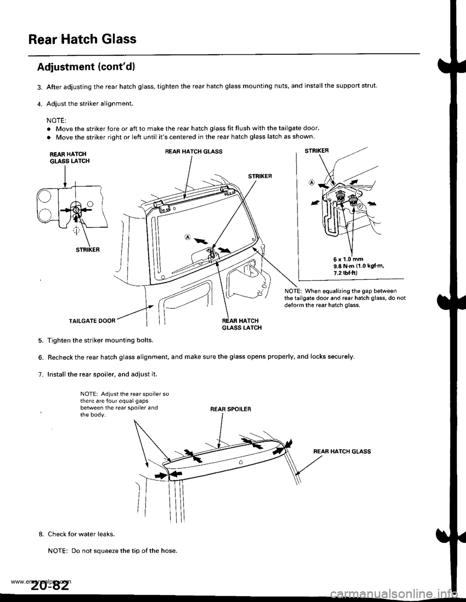
After adjusting the rear hatch glass, tighten the rear hatch glass mounting nuts, and installthe support strut.
Adjust the striker alignment.
NOTE:
. Move the striker fore or aft to make the rear hatch glass fit flush with the tailgate door'
. Move the striker right or left until it's centered in the rear hatch glass latch as shown.
REAR HATCHGLASS LATCH
STRIKER
NOTE: When equalizing the gap betweenthe tailgate door and rear hatch glass, do notdglorm the rear hatch glass.
TAILGATE DOOR
5. Tighten the striker mounting bolts.
6. Recheck the rear hatch glass alignment. and make sure the glass opens properly, and locks securely.
7. Installthe rear spoiler. and adjust it.
NOTE: Adjust the rear spoiler sothere are four equal gaps
between the rear spoiler andthe body.REAR SPOILER
REAR HATCH GLASS
8. Check for water leaks.
NOTE: Do not squeeze the tip of the hose.
20-82
REAR HATCH GLASS
6x1.0mm9.8 N.m (1.0 kgt'm,
7.2tbl.ftl
www.emanualpro.com
Page 1085 of 1395
Sub-frame
Sub-frame To.que Sequence:
CAUTION: After loo3ening the sub-frame mounting bolts, be sure to replace them with now ones.
REAN CROSSBEAM
10 r 1.25 mm49 N.m 15.0 kg{.m,36 tbt.ftl12 x 1.25 mm74 N.m (7.5 kgtm.54 tbf.ft)
BOLTS1l x 1.5 mm89 N.m 19,1 kgt m,66 tbt ftlReplace.
SNFFENER
20-104
www.emanualpro.com
Page 1136 of 1395
Heater Control PanelBlower Unit
Replacement
'1.Remove the center panel together with the heater
control panel and the audio unit (see section 20).
Remove the self-tapping screws and the heater con-
trol panel from the center panel.
3. lnstall in the reverse order of removal.
CENTER PANEL
22-46
1.
Replacement
Bemove the evaporator (see page 22-48),
Disconnect the connectors from the blower motor,
the blower motor high relay, the power transistor
and the recirculation control motor. Remove the
wire harness clio from the recirculation control
motor, and release the wire harness from the clamp
on the blower unit. Remove the mounting bolts, the
mounting nut and the blower unit.
6x1.0mm9.8 N.m (r,0 kgf.m, 7.2 lbl.ftl
9.E N.m 11.0 kgf.m,7.2lbtftl
lnstall in the reverse order of removal. Make sure
that there is no air leakage.
6x1.0mm
www.emanualpro.com