1997 HONDA CR-V Installation
[x] Cancel search: InstallationPage 892 of 1395
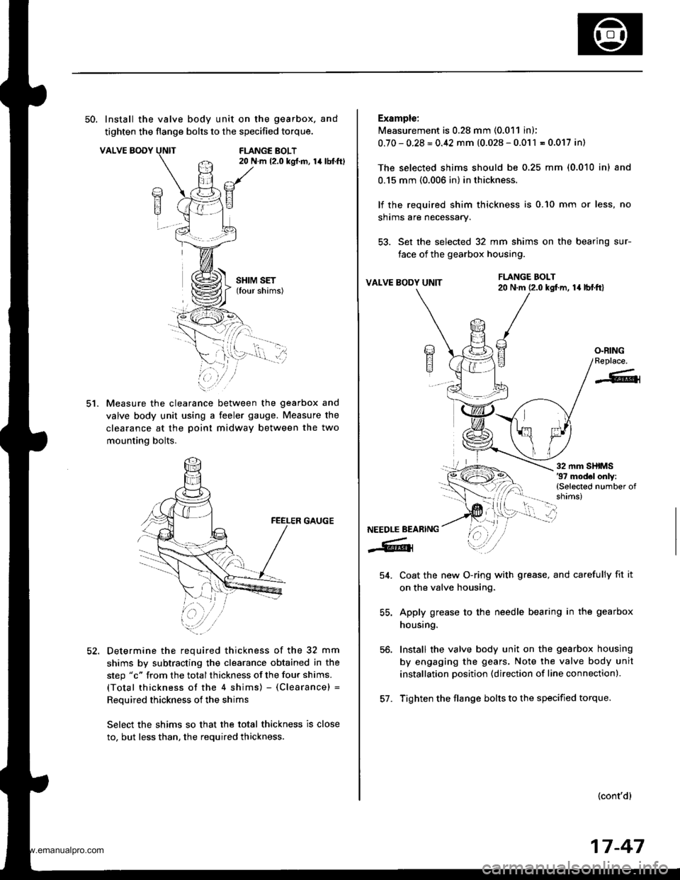
50. Install the valve body unit on the gearbox. and
tighten the flange bolts to the specified torque.
VALVE BODYFLANGE BOLT20 N.m 12.0 kgt.m, 14lbtft)
ct.
SHIM SET(four shims)
Measure the clearance between the gearbox and
valve body unit using a feeler gauge. Measure the
clearance at the poinl midway between the two
mounting bolts.
GAUGE
Determine the required thickness of the 32 mm
shims by subtracting the clearance obtained in the
step "c" from the total thickness of the four shims.
(Total thickness of the 4 shims) - (Clearance) =
Reouired thickness of the shims
Select the shims so that the total thickness is close
to, but less than, the required thickness.
Example:
Measurement is 0.28 mm (0.011 in);
0.70-0.28=0.42 mm (0.028-0.011 = 0.017 in)
The selected shims should be 0,25 mm (0.010 inl and
0.15 mm (0.006 in) in thickness.
lf the required shim thickness is 0.10 mm or less, no
shrms are necessary.
53. Set the selected 32 mm shims on the bearing sur-
face of the gearbox housing.
VALVE BODY UNITla lbl.frl
Coat the new O-ring with grease, and carefully fit it
on the valve housing.
Apply grease to the needle bearing in the gearbox
housing.
Install the valve body unit on the gearbox housing
by engaging the gears. Note the valve body unit
installation position (direction of line connection).
Tighten the flange bolts to the specified torque.
(cont'd)
FLANGE BOLT20 N.m (2.0 kgf.m,
/a)E?
E
O.RINGReplace.
-6{
NEEDLE BEARING
-6lr
54.
56.
57.
17-47
www.emanualpro.com
Page 895 of 1395
Power Steering Gearbox
Reassembly (cont'd)
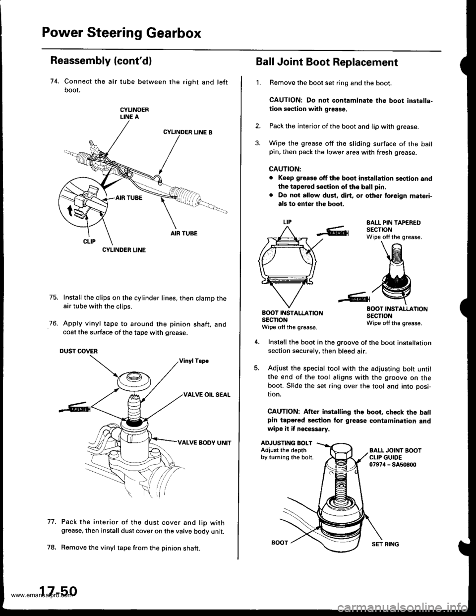
74. Connect the air tube between the right and left
boot,
CYLINDERLINE A
75. Install the clips on the cylinder lines, then clamp theair tube with the clips.
76. Apply vinyl tape to around the pinion shaft, andcoat the surface of the tape with grease.
DUST COVER
Vinyl Tsp€
VALVE OIL SEAL
VALVE BODY UNIT
Pack the interior of the dust cover and lio withgrease, then install dust cover on the valve bodv unit.
Remove the vinyl tape f.om the pinion shaft.
77.
CYLINDER LINE
17-50
SET RING
't.
Ball Joint Boot Replacement
Remove the boot set ring and the boot.
CAUTION: Do not contaminate the boot inslalla-
tion section with graase.
Pack the interior of the boot and lip with grease.
Wipe the grease off the sliding surface of the ballpin. then pack the lower area with fresh grease.
CAUTION:
. Keep grease off the boot installation section and
the tapered section of th€ ball pin.
. Do not allow dust, dirt, or other to.eign materi-
als to enter the boot.
EALL PIN TAPEREDSECTIONWipe olf the grease.
BOOT INSTALLATIONSECTIONWipe offthe grease.
B(X)T IT{STALLATIONsEclroNWipe off the grease.
ADJUSTING BOLTAdiust the depthby turning the bolt.
Install the boot in the groove of the boot installation
section securely. then bleed air.
Adjust the special tool with the adjusting bott untilthe end of the tool aligns with the groove on theboot. Slide the set ring over the tool and into posi-
I|on.
CAUTION: After installing the boot, chock the batlpin lapered section for grease contamination andwipe it it n€cessary.
www.emanualpro.com
Page 897 of 1395
Power Steering Gearbox
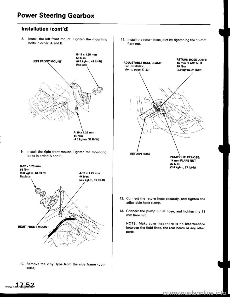
Installation (cont'd)
8, Install the left front mount. Tighten the mountingbolts in order: A and B.
LEFT FRONT MOUNT
B-12 x 1,25 mm59Nm(6.0 kgtm,,€ lbl.ftlReplaca.
9. Instsll the right front mount, Tighten the mountingbolts in order: A and B.
B-12 x 1.25 mm59 N.m16.0 ks[.m, ,|:| lbf.ftlReplace.
A-10 x 1.25 mm4,1 N.mla.s kgt m, 33 lbf.ft)
A-10 x 1.25 mma,a N.m
10. Remove the vinyl type from the side frame (both
sides).
17-52
11. Installthe return hose joint by tightening the 16 mmflare nut.
AD.'USTAB[T HOSE CLAMP(For installationreter to page 17,23)
RETURN HOSE JOINT:16 mm FLARE NUT28 N.m12.9 kg{.m.21 lbt{t)
14 mm FLARE NUT37 N.m(3.8 ksf.m, 27 lbl'frl
't2.
13.
Connect the return hose securely. and tighten theadjustable hose clamp.
Connect the pump outlet hose, and tighten the l4mm flare nut.
NOTE: Make sure that there is no interferencebetween the fluid lines, the rear beam or any otherparts.
www.emanualpro.com
Page 898 of 1395
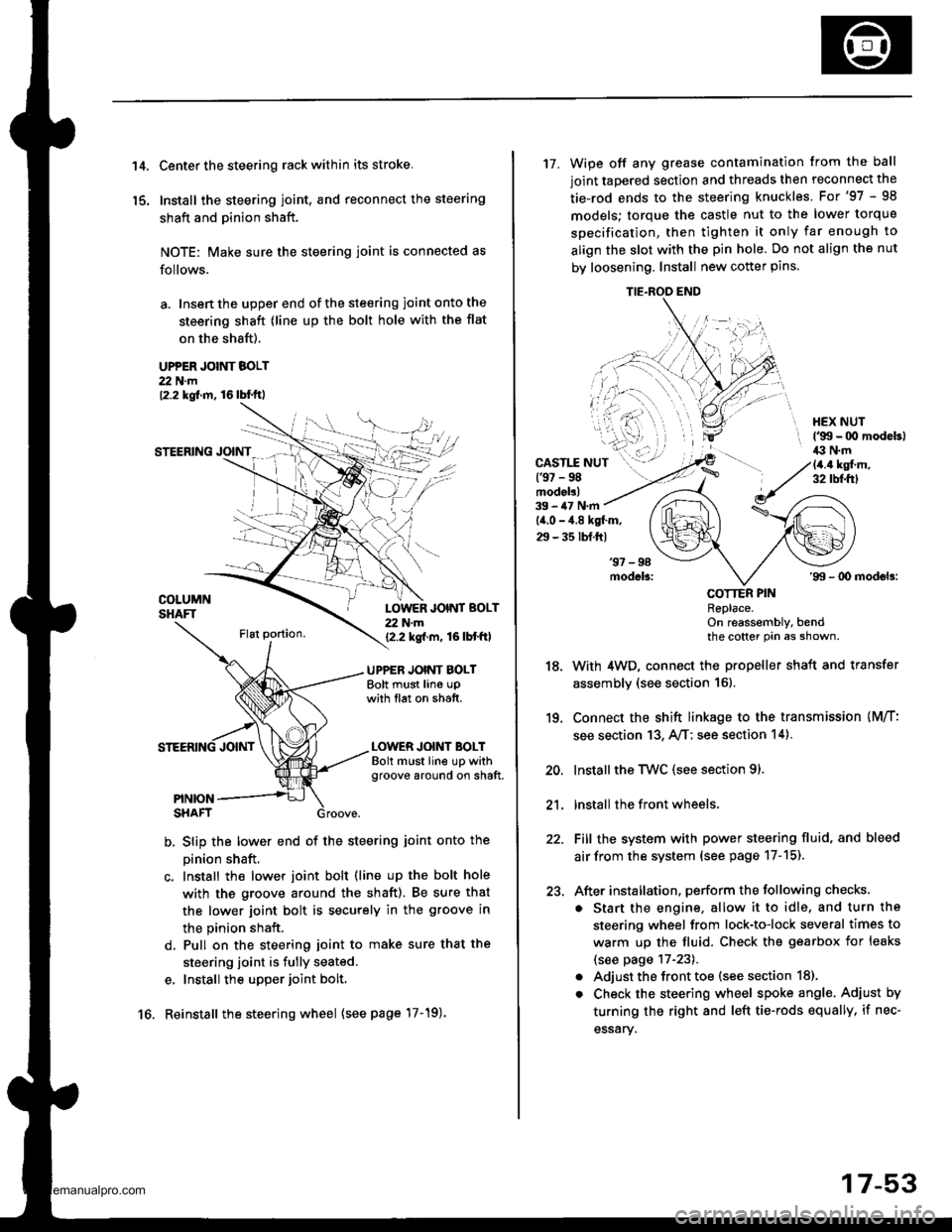
't 4.
15.
Center the steering rack within its stroke.
Install the steering joint, and reconnect the steering
shaft and pinion shaft.
NOTE: Make sure the steering joint is connected as
follows.
a. Insen the upper end of the steering joint onto the
steering shaft (line up the bolt hole with the flat
on the shaft).
UPPER JOINT BOLT22 N.m12.2 kgf.m, 16lbl.ft,
STEERING JOINT
COLUMNSHAFTLOWER JOINT BOLT22 N.m12.2 kgf.m, 16lbtftl
UPPER JOINT BOLTBolt must line upwith tlat on shatt.
LOWER JOINT BOLTBolt must line up withgroove around on shaft.
PINIONSHAFT
b, Slip the lower end of the steering ioint onto the
pinion shaft.
c. Install the lower joint bolt (line up the bolt hole
with ths groove around the shaft). Be sure that
the lower joint bolt is securely in the groove in
the pinion shaft.
d. Pull on the steering joint to make sure that the
steering joint is fully seated.
e, Install the upper joint bolt,
Reinstall the steering wheel {see page'17-19).16.
17-53
17. Wipe off any grease contamination trom the ball
joint tapered section and threads then reconnect the
tie-rod ends to the steering knuckles. For'97 - 98
models; torque the castle nut to the lower torque
specification, then tighten it only far enough to
align the slot with the pin hole. Do not align the nut
by loosening. Install new cotter pins.
CAST1T NUT(9t - 98modol!)
HEX NUTl'g!t - 00 modeb)il:l N.m14.4 ksl.m,32 tbf.f0
39 - iU N'm
lil.o - 4.8 kgl.m,
29 - 35 tbf.ftl
18.
19.
20.
21.
22.
23.
'99 - lD modeb:
COTTER PINRePlace.on reassembly, bendthe cotter Pin as shown.
With 4WD, connect the propeller shaft and transfer
assembly (see section 16).
Connect the shift linkage to the transmission (M/T:
see section 13, A,/T; see section 14).
Installthe Twc (see section 91.
lnstall the front wheels,
Fill the system with power steering fluid, and bleed
air from the system (see page 17-15).
After installation. perform the following checks.
. Start the engine, allow it to idle, and turn the
steering wheel from lock-to-lock several times to
warm up the fluid. Check the gearbox for leaks
(see page 17-23).
. Adjust the front toe (s€e section 18).
. Check the steering wheel spoke angl€. Adjust by
turning the right and left tie-rods equally, if nec-
essary.
TIE.ROO END
www.emanualpro.com
Page 909 of 1395

12.
13.
14.
Clean any dirt or grease off the ball joint.
Remove the cotter pin from the steering arm, and
remove the nut.
Apply grease to the special tool on the areas shown.
This will ease installation of the tool and prevent
damage to the pressure bolt threads.
PRESSURE BOLT
lnstall a 10 mm hex nut on the ball joint. Make sure
the hex nut is flush with the ball joint pin end to
prevent damage to the threaded end of the ball
joint.
BALL JOINT REMOVER, 28 mm07MAC - SL(x)2(x)HEX NUT
HEX NUT10 x 1.25 mm('99 modcll43 N.mlit.a kgl.m.32 tbtft)
37 -98 models:
tc.
6:)
CASTLE NUT10 x '1.25 mm
l'97 - 98 modcls)39 - 47 N.m{4.0 - 4.829 - 3s rbtftt
COTTERReplace.On re6ss€mbly,bend the cofter pin
16. Install the special tool as shown. Insert the jaws
carefully, making sure you do not damage the balljoint boot. Adiust the jaw spacing by turning the
pressure bolt. lf necessary, apply penetrating type
lubricant to loosen the ball ioint.
'99 -00 modol:
18.
17. Once the special tool is in place, turn the adjusting
bolt as necessary to make the jaws parallel. Then
hand-tighten the pressure bolt, and recheck thejaws to make sure they are still parallel.
ADJUSTING BOLT
After making the adjustment to the adjusting bolt,
make sure the head of the adjusting bolt is in this
position to allow the jaw to pivot.
With a wrench, tighten the pressure bolt until the
ball joint shaft pops loose from the steering arm.
@ wear eye protection. The balt iointcan break loose suddenly and scatter dirt or other
dsbris in your ey€s.
Remove the tool, then remove the nut from the end
of the ball joint, and pull the ball joint out of the
steering/suspension arm. Inspect the ball joint boot.
and replace it if damaged.
(cont'dl
1(|
18-1 1
www.emanualpro.com
Page 914 of 1395
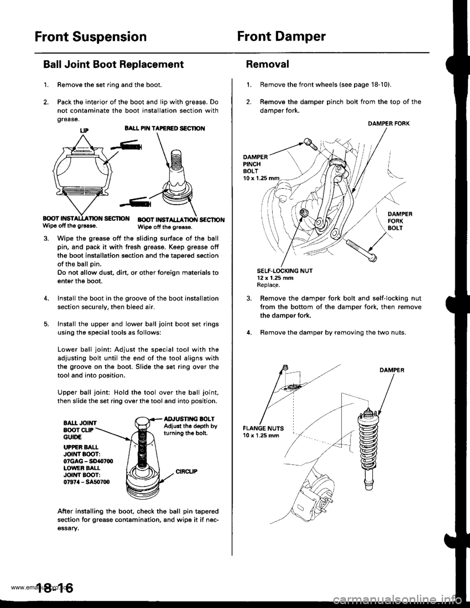
Front SuspensionFront Damper
Ball Joint Boot Replacement
1.
BALL PIT{ TAPEFEO S€CTION
B{rcY HSISECTIO BOOT |NSTSECTIONwip6 off tho gr6aso.Wipo otf th6 grors€.
Wipe the grease off the sliding surface of the ball
pin, and pack it with fresh greass. Keep grease off
the boot installation section and the taoered section
of the ball pin.
Do not allow dust, dirt, or other foreign materials to
enter the boot.
Install the boot in the groove of the boot installation
section securelv, then bleed air.
Install the upper and lower ball joint boot set rings
using the special tools as follows:
Lower ball joint: Adjust the special tool with the
adjusting bolt until the end of the tool aligns with
the groove on the boot. Slide the set ring over the
tool and into oosition.
Upper ball joint: Hold the tool over the ball joint,
then slide the set ring over the tool and into position.
EAII JOINTAD'USN G BOLTAdjust th6 depth byturning the bolt.
Remove the set ring and the boot.
Pack the interior of the boot and lip with grease. Do
not contaminate the boot installation section with
grease.
B(X)T CUPGUttrE
UPPER BAI.IJott'tr Boor:07GAG - SO407q)LOWEF BATIJOIIYI EOOTI0t97il - SA507lXl
After installing the boot, check the ball pin tapered
section for grease contamination, and wipe it if nec-gssary.
18-16
Removal
1, Remove the front wheels (see page 18-10).
2. Remove the damper pinch bolt from the top of the
damper fork.
DAMPERPINCHBOLT'10 x 1.25
SELF.LOCKING NUT12x 1.25 fifiReplace.
Remove the damper fork bolt and self-locking nut
from the bottom of the damper fork, then remove
the damper fork.
Remove the damper by removing the two nuts.
DAMPER
DAMPER FORK
www.emanualpro.com
Page 934 of 1395
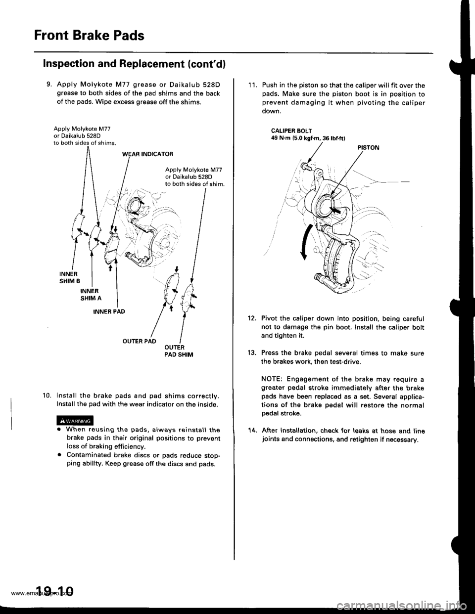
Front Brake Pads
Inspection and Replacement (cont'dl
9. Apply Molykote M77 grease or Daikalub 528Dgrease to both sides of the pad shims and the back
of the pads. Wipe excess grease off the shims.
Apply Molykote M77
to both sides of shims.
INOICATOR
Apply Molykote M77or 0aikalub 528Dto both sides of shim.
10.
INNER PAD
OUTER PAD
lnstall the brake pads and pad shims correctly.
Install the pad with the wear indicator on the inside.
. When reusing the pads, always reinstall thebrake pads in their original positions to prevent
loss of braking efficiency.. Contaminated brake discs or pads reduce stop-ping ability. Keep grease off the discs and pads.
19-10
'11. Push in the piston so that the caliper willfit over thepads. Make sure the piston boot is in position toprevent damaging it when pivoting the caliper
down.
CALIPER BOLT49 N.m (5.0 kgf.m, 36 lbf.ftl
13.
Pivot the caliper down into position, being careful
not to damage the pin boot. Install the caliper bolt
and tighten it,
Press the brake pedal several times to make sure
the brakes work, then test-drive.
NOTE: Engagement of the brake may require agreater pedal stroke immediately after the brakepads have been replaced as a set. Several applica-
tions of the brake pedal will restore the normalpedal stroke.
After installation, check for leaks at hose and linejoints and connections, and retighten if necessary.
14.
www.emanualpro.com
Page 937 of 1395

Master Cylinder/Brake Booster
Removal/lnstallation
1, Disconnect the brake fluid level switch connectors.
2. Remove the reservoir cap from the master cylinder.
3. Remove the brake fluid from the master cvlinder
reservoir with a syringe.
4. Disconnect the brake lines from the master cylinder.
To prevent spills, cover the line joints with rags or
shop towels.
5. Remove the master cylinder mounting nuts and
wasners.
6. Remove the master cylinder from the brake booster.
CAUTION: Be careful not to bend or damage the
brake lines when removing the master cylinder.
Do not spill brake fluid on the vehicle; it may dam.
age the paint; it brake fluid does cont.ct the paint,
wash it oft immediately with water.
7. Disconnect the vacuum hose from the brake booster.
8. Remove the cotter pin and clevis pin from the clevis.
Do not disconnect the clevis by removing it from
the operating rod of the brake booster. lf the clevis
is loosened, adjust the pushrod length before
installing the brake booster (see page 19-15).
To Front Caliper (Without ABS)
\\
15 N.m {1.5 kgtm, vAcuuM HosE
r r rbf.ft) |
/ | BRAKE FLUTD LEvEL
/l /
swrrcHcoNNEcroRs
/ I I I COTTER PIN
I I / neotace
l,/-- ro Rear wheet cylinders / | I
h ./-''' /. I I IYli //*s (.S
I /r:
9. Remove the four booster mounting nuts.'10. Pull the brake booster forward until the clevis is
clear of the bulkhead.
11. Remove the brake booster from the enqine com-
panment.
12. Install the brake booster and master cylinder in the
reverse order of removal, and note these items:
. When connecting the brake lines, make sure that
there is no interference between the brake lines
and other parts.
. Be careful not to bend or damage the brake lines
when installing the master cylinder.
. lf replacing the master cylinder or brake booster,
check and adjust the pushrod clearance before
installing the master cylinder (see page 19-14).
Fill the master cylinder reservoir, and bleed the
brake system (see page 19-7).
After installation, check the brake pedal height and
brake pedal free play (see page 19-5), and adjust if
necessary.
13 N.m 11.3 kg{.m,I rbf.ft)
13.
14.
To Master Cylinder(Without ABS)To Modulator Unit(with ABs)@-\
\
^ To Front Caliper
9i\.
-#qCLEVIS PIN
):-,/
PROPORTIONING CONTROL VALVE
MASTER CYLINDER
15 N.m (1.5 kgf.m, 11 lbl.ftl
BRAXE BOOSTER
www.emanualpro.com