Page 1277 of 1395
Circuit Diagram (Rear Windowl -'98 - 00 Models
BATTERYUNDER.HOOD FUSEi RELAY 80X
N0.41 (100A) N0.42 (40A)
@*,'WHT/BLK +WHTGNIT ONSW TCH
REAR WINDOWWPER MOTOR
Ot-
GRN/BLK
I
A n',$s".,,,
vil8t8E
IBLK
I
n-
G202
BLK
n_-:
G611G631
UNDEF-DASHFTJSE/RELAYBOX
JDLI OFF
INTEGRATED CONTROL UN T/Has bo ll-in re wndow\
t nlermillenl w per relay ]
BLK
.L-
G40lG402
I
-
23-117
www.emanualpro.com
Page 1284 of 1395
Power Door Locks
UNDER.HOOD FUSE/FELAY BOX
Circuit Diagram (With Keyless Entry System)
GN TION SW TCHUNDER DASHFUSE/RELAY BOXEATTEFY
@*n'
WHT/GFN
8
ITEYLES--lI TRANSMIT]ER ILr--------
. PASSENGENS DOOR SWITCHES. ]NTEGRATED CONTROL UNIT5
23-124
HORNRELAY
f7
II- GRY
FRONTCEILINGL GHT
Y_o*,,.,,,0-
HATCHGLASSOPENERSOLENO D
HATCH
OPENERswlTcH
f7
I
YEL
L
fIllBl
+BL(
I
G61lG63l
INTEGRATED ICoNTROL UN T I
,Y, I
F",'*-{
.,ufrro I
tl
rthg#,i."J L
T
8!?i"'[:lll',fffi)
BLK
I
I--
G401G402
YEL
8LK
I
G551
DRIVER'SDOOF LOCKswrTcH
UNLOCK
nrrenu @
LOCK
@
KEYLESSDOOs LOCKCONTROL UNIT
BLK
I
G551
--1
www.emanualpro.com
Page 1285 of 1395
UNDER-DASHFUSE/RELAYBOX
Circuit Diagram {Without Keyless Entry System)
IGNTION SWITCHBATTEBY
@**'
FRONTCEILINGTIGHT
V
l_
r-
HATCHGLASSOPENERSWTCH
f7
I
l-J';
tr| oBtvERsI DOOn LOCKACTUATOR
s l-lLocx^l-Tq. l,, | -=tGJ--
+ II Locx IDRIVER'SD00R LOC(SWITCN
KNOB
6 tr.*;lwrr 3-K +wqr-t_t- BLKYEL
ffr
vEL
YEURED
GRNORN
GRNWHT
HORNRELAY
V
BLK
II
I:
G551
23-125
INTEGRATEDCONTROL UNIT
V
IBLU/RED
I
l- 8Lr
IBLU/RED
II
Iupl ,#. L?Vno'::iii^ ( li: ) swrTcHYAil''"',4,.'{yrcLosED
l' tottt
IBLK
II
I':
G()1G402
YEL
t/ |
tFl
?BLK
I
G6l1
UNDER.HOOD FUSEi RELAY 8OX
(Nol used)
LOCK
o
POWERDOOR LOCKCONTROL UNIT
EIGHT REAR00oR LocKACTUATOR
'tl
www.emanualpro.com
Page 1287 of 1395

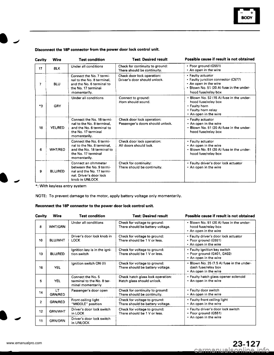
Disconnoci the 18P connestor from the pow€r door lock control unit.
Cavity WireTest conditionTost: Dcsired resultPo$ible csuse il result is not obtainod
Possible cause if result is not obtain€d
*: With keyless entry system
NOTE: To prevent damage to the motor, apply battery voltage only momentarily.
Feconnoct the 18P conneqtor to the power door lock control unit,
Cavity Wir6Test conditionTost: D€sirod result
118LKUnder all conditionsCheck for continuity to ground:
Ther€ should be continuity.
. Poorground (G55'l). An open in the wire
7BLU
Connect the No. 7 termi'nalto the No. 8 terminal,and the No. 6 terminal tothe No. 17 terminalmomentarily.
Check door lock operation:Driver's door should unlock.Faulty actuatorFaulty junction connector (C577)
An open in the wireBlown No. 51 (20 Al{use in the under-
hood fuse/relay box
GRY
Under all conditionsConnect to ground:Horn should sound,Blown No. 52 (15 A)tuso in the under-hood fuse/relay boxFaulty hornFaulty horn relayAn open in tho wire
YEURED
Connect the No. 'l8 termi-nalto the No. 8 terminal,and the No. 6 terminal tothe No. 17 terminalmomentarily.
Check door lock operation:Passenger's doors should unlock.Faulty actuatorAn open in the wireBlown No.51 (20 A)fuse in the under-hood fuse/relay box
WHT/RED
Connect the No.6termi-nal to th6 No. I terminal,and the No. 18 terminal tothe No. 17 terminalmomentarily.
Check door lock operationlAll doors should lock.Faulty actuatorAn open in the wireBlown No. 51 {20 A) fuse in ihe under-hood fuse/relay box
9BLU/RED
Connect an ohmmeterbetween the No. 9 termi-nal and the No. l7 termi-nal. Driver's door lockknob in UNLOCK
Check for conlinuity:There should be continuity.
' Faulty driver's door lock actualor. An open in the wire
WHT/GRNUnder all conditionsCheck for voltage to ground:
There should be battery voltage.Blown No. 51 (20 Alfuse in the under-hood tuse/relay boxAn open in the wire
10BLUAVHTDriver's door lock knob inLOCKCheck tor voltage to ground:There should be 1 V or less.Faulty driver's door lock actuatorPoor ground (G551)
An open in the wire
13BLU/REDlgnition key is in the igni-tion switchCheck tor voltage to ground:
There should b€ 1 V or less.Faulty ignition key switchPoor ground (G401, G402)An open in the wire
YELlgnition switch ON (ll)Check for voltage to ground:
There should be battery voltage.Blown No. 25 (7.5 A) fuse in the under-dash fuse/relay boxAn open in the wire
5YELConnect the No. 5terminal to the No. I ter-minal momentarily
Check hatch glass lock operation:Hatch glass should unlock.
. Faulty hatch glass opener solenoid. An opon in the wire
14LTGRN,NEDPassengor's door openCheck for continuity to ground:There should b€ continuity.
. Fa(llty door switch. An open in the wire
2GRN/R€DFront ceiling light"MlDDLE" positionCheck tor voltage to ground:There should be battery voltage.Faulty lront ceiling lightAn open in the wire
12GRNAr'VHTDriver's door lock switchin LOCKCheck lor voltage to ground:There should be 1V or less.Faulty driver's door lock switchPoor ground {G551)An open in the wire' GRN/ORNDriver's door lock switchin UNLOCK-
23-127
www.emanualpro.com
Page 1315 of 1395
Circuit Diagram
UNDER.DASHFUSE/RELAYBOX
NOTE: The SRS main harness uses all GRY('97 model) or GRN ('98 - 00 models) wires.
WHT/BLK -'- WHT
DRIVEB'SAIRBAGNFLATOR
A
#+
tt tll./ d I
GRY GRY(GRN) (GRN)
FRONTPASSENGER'SALRBAGINFLAlOR
tlGRY GFY(GFN) (GRN)
DRIVER'SSEAT EELTTENSIONER
FRONTPASSENGERSSEAT BELTTENSIONEF
GRN(BLU/PNK)
BLK
G401
24-18
PCM/ECM SERVICE MEMORY ERASECHECK S GNAL (MES)CONNECTOB CONNECTOR(2P)
DATA LINXCONNECTOR(Drc) (r6P)
Models)('98 - 00
IGNITION SWITCHUNDEF,HOOD FUSE/RELAY BOX
YEUGRN
+
PGM FImam relay
SFS INDICATOR CIRCUIT(ln lhe gauge assembly)
Shill loc* so enoid
BLU
GR\
GNY GRY
H
GFY GRYlcFNt (GlN)
??
I r-?LT BLU BRN BRN
tttr?F?F
VVV
SRS NDICATORL GHT {r.4W)
5 12 4 11 | 16 17 15 I 18 I
10 14 113
U
S8S UN T TERMINALS
3567I
101114151718
Terminal side of male terminals
-4
www.emanualpro.com