Page 1251 of 1395

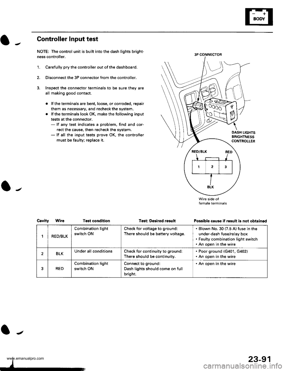
Controller Input test
NOTE: The control unit is built into the dash lights bright-
ness controller.
1.Carefully pry the controller out of the dashboard.
Disconnect the 3P connector trom the controller,
Inspect the connector terminals to be sure they are
all making good contact.
. lf the terminals are bent, loose, or corroded, repair
them as necessary, and recheck the system.
. lf the terminals look OK, make the following input
tests at the connector.- lf any test indicates a problem, find and cor-
rect the cause. then recheck the system.- lf all the input tests prove OK, the controller
must be taulty; replace it.
CsvityWireT€st condhion
Wire side oflemale terminals
Possible cause if result is not obi8inod
OASH LIGHTSBRIGHTNESSCONTROLLER
Tsst: Desired resuli
1R ED/BLK
Combination light
switch ON
Check for voltage to ground:
There should be battery voltage.
Blown No. 30 (7.5 A) fuse in the
under-dash fuse/relay box
Faulty combination light switch
An open in the wire
2BLKUnder all conditionsCheck for continuity to ground:
There should be continuitv.
. Poor ground (G401, G402). An open in the wire
5RED
Combination light
switch ON
Connect to ground:
Dash lights should come on full
bright.
. An open in the wire
23-91
www.emanualpro.com
Page 1254 of 1395
Interior Lights
Ceiling Laght Test
Front and rgar:
1. Turn the light switch OFF.
2. Pry off the lens.
3. Remove the two mounting nuts and the housing.
4. Disconnect the 3P connector from the housing.
Check for continuity between the terminals in each
switch position according to the table.
t€rmtnar
Position \
1or1'�2'3'�3
OFFo-Pd'l-o
MIDDLEo-/=\-o
ONo-/a\-o\:/
23-94
1 1' 3' 2'
Spotlight Test
1. Turn the spotlight switch OFF.
2. Pry off the lens.
3. Remove the two screws and the housing.
4. Disconnect the 3P connector from the housing.
Check for continuitv between the terminals in each
switch position according to the table,
Terminal
t"",rr" \12ol2'�3
R
ONo-/-\--o\:./
OFFo@o
L
ONo-/a--o\:./
OFFo-(9--o
aULB(5Wx2l
www.emanualpro.com
Page 1256 of 1395
Accessory Socket
Accessory Socket Test/Replacement
Front Accessory Socket:
1. Remove the center dashboard lower cover (see sec-
tion 20).
Disconnect the 2P connector from the front accessory
socket.
Inspect the connector terminals to be sure they are
all making good contact.
2.
lf the terminals are bent, loose or corroded, repair
them as necessary, and recheck the system.
lf the terminals look OK, go to step 4.
ACCESSORYSOCKET
Turn the ignition switch to ACC (l), and check for
voltage between the No. 1 and No. 2 terminals.
. There should be battery voltage.
. lf there is no battery voltage, check for:- blown No.27 (10 A) fuse in the under-dash
fuse/relay box.- poor ground (G401, G402).- an open in the wire.
23-96
5. If all the tests prove OK, replace the front accessory
socket.
PBOTECTOB
FACE PANEL
www.emanualpro.com
Page 1257 of 1395
Rear Accessory Socket:
'1. Remove the left rear side trim panel {see section
20t.
2.Disconnect the connectors.
lnspect the connector terminals to be sure they are
all making good contact.
lf the terminals are bent, loose or corroded,
repair them as necessary, and recheck the sys
tem.
. lf theterminals look OK, goto step 4.
ACCESSORYSOCKET
A (YEL/8LUI
3.
\J
ryIIBLK}
4. Turn the ignition switch to ACC (l), and check tor volt
age between the A and B terminals.
o There should be battery voltage.
. lf there is no battery voltage, check for:- blown No. 6 ('10 A) and No. 27 (10 A) fuses in
the under dash fuse/relay box.- faulty rear accessory socket relay (test, page
23-53).- poor ground (G401, G402, G553).- an open in the wire.J
23-97
5. Remove the thermofuse housing and thermal pro
tector, then remove the socket and cover.
THEEMALPROTECTOR
T$THERMOFUSEHOUSING
COVER
SOCKET
www.emanualpro.com
Page 1259 of 1395
Removal
1. Remove the center air vent (see section 20).
2, Disconnect the 4P connector.
3. Remove the two screws.
CENTER AIRVENT
CLOCK
IIt
-
23-99
Terminals
Connects to
IWHT/BLUConstant power (time
memory)
YELlG1 (main clock power supply)
RED/BLKLights-on signal
4BLKGround {G401, G402}
www.emanualpro.com
Page 1262 of 1395

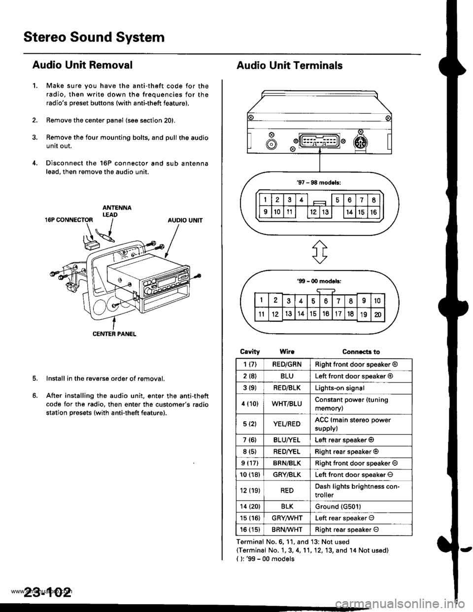
Stereo Sound System
Audio Unit Removal
Make sure you have the anti-theft code for the
radio, then write down the frequencies for the
radio's preset buttons (with anti-theft feature).
Remove the center panel (see section 201,
Remove the four mounting bolts, and pull the audio
unit out.
Disconnect the 'l6P connector and sub antenna
lead, then remove the audio unit.
Install in the reverse order of removal.
After installing the audio unit, enter the anti-theft
code for the radio. then enter the customer's radio
station presets (with anti-theft feature).
1.
AUDIO UNIT
CENTEB PANEL
23-102
Audio Unit Terminals
CavrtyWireConnoct3 to
Terminal No.6, 11, and 13: Not used(Terminal No. 1,3, 4,'11,12, 13, and '14 Not us6d)
{ ): '99 - 00 models
1{7)RED/GRNRight front door speaker @
2 {8}BLULeft front door speaker @
3 {9)RED/BLKLights-on signal
4 (10)WHT/BLUConstant power (tuning
memory)
5 (2)YEUREDACC (main sterso power
supplyl
7 (6)BLU/YELLeft rear soeaker @
8 (s)RE D/VELRight rear speaker @
9 (17)BRN/BLKRiqht f.ont door speaker O
10 (18)GRY/BLKLeft front door soeaker O
12 (19)REDDash lights brightness con-
troller
14 (20)BLKGround (G501)
15 (16)GRYMHTLeft rear speaker O
16 (15)BRN^ll/HTRight resr speaker O
www.emanualpro.com
Page 1263 of 1395
Speaker Replacement
1. Remove the speaker cover.
2. Remove the three screws from the speaker.
3. Disconnect the 2P connector, and remove the door
speaker.
Front speaker:
2P CONNECTOR
Rear speaker:
/a--=-
ll-
FRONT SPEAKER
SPEAKERCOVER
4-
23-103
Mast Antenna Replacement
NOTE: To remove the antenna lead, it is necessary to
remove the dashboard (see section 20).
1. Disconnect the antenna lead from the audio unit.
2. Remove the two mounting screws, then remove the
mast antenna.
MOUNTING SCREWS
www.emanualpro.com
Page 1265 of 1395
Horn Test
1. Remove the front bumper (see section 20).
2. Disconnect the 2P connector from the horn
3, Remove the horn.
2P CONNECTOR
Test the horn by connecting battery power to one
terminal and grounding the other. The horn should
sound.
4.
HORN
23-105
5. lf the horn fails to sound, replace it
Circuit Diagram
}-BLU/FED
I
BLUi FEO BLU/RED
II
g)iirrN I
tlBLK BLK
ll
IBLK
I
I
I
G201
fl"'
LOWHORN
KEYLESSiPOWEFDOOR LOCKCONTROLUNIT
www.emanualpro.com