Page 974 of 1395

(From page 19-50)
Chcck for .n opsn in the PCOMcircuit:1. Turn the ignition switch OFF.2. Reconnect the ABS controlunit 22P connector.3. Connect the SCS service con-nector.4. Turn the ignition switch ON {ll).5. Measure the voltage betweenthe pump motor relay con-nector PCOM terminal andbody ground.
Repair opon in the wire betwoenthe under-hood ABS fuse/relaybox and tho ABS conlrol unh.ls there approx.3 V?
Check for an open in tho PMR cir-cuh:Measure the voltage between theABS control unit 22P connectorterminal No. 19 and body ground.
Ropair open in tho wir6 botwagntho undcr-hood ABS fuse/rolaybox .nd the ABS control unit.ls there approx. 3 V?
Ch.ck tor an opon in the MCKci.cuit:1. Turn the ignition switch OFF.2. Disconnect the SCS serviceconnector.3. Turn the ignition switch ON (ll).
4. Measure the voltage betweenthe ABS control unit 22P connector terminal No. 17 andbody ground while connect-ing the pump motor relayconnector +B and MOTOR ter-minal with a jumper wire tormoment,
Repair open in the wiro bdtweenthe under-hood ABS fus6/telaybox .nd the ABS control unit.ls there battery voltage?
Chock for loose ABS control unitconnectoas, It necsssary, substi-tule a known-good ABS controlunit and aocheck.
tr) l--l
r"r
ABS CONTROL UNIT 22P CO NECTOR
Wire side of female terminals
1t011
MCK IBRN,/YEL}
www.emanualpro.com
Page 975 of 1395
![HONDA CR-V 1997 RD1-RD3 / 1.G Workshop Manual
Troubleshooting
DTG 54: Main Relay
IWHT/GRNI
AAS CONTROL UNIT 26P CONNECTON
Wire side of female terminals
ABS COf{TROL UN]T 22P CONNECTOR
PCOMIGRN/WHTIscoM{BLK/WHTI
Wire side of female terminals
- Wi HONDA CR-V 1997 RD1-RD3 / 1.G Workshop Manual
Troubleshooting
DTG 54: Main Relay
IWHT/GRNI
AAS CONTROL UNIT 26P CONNECTON
Wire side of female terminals
ABS COf{TROL UN]T 22P CONNECTOR
PCOMIGRN/WHTIscoM{BLK/WHTI
Wire side of female terminals
- Wi](/manual-img/13/5778/w960_5778-974.png)
Troubleshooting
DTG 54: Main Relay
IWHT/GRNI
AAS CONTROL UNIT 26P CONNECTON
Wire side of female terminals
ABS COf{TROL UN]T 22P CONNECTOR
PCOMIGRN/WHTIscoM{BLK/WHTI
Wire side of female terminals
- With the ignition switch ON(lll, the ABS indicator doesnot go off.- With the SCS service connec-tor connected {see page 19-381,DTC 54 is indicatod.
Check the ABS +B 120 A) fuse inthe under-hood ABS luse/relaybox, and reinstall the fuse if it isoK.
FeDlace the tu3e and recheck.
Ch€ck tor an open in the 81, 82circuit:Measure the voltage betweenbody ground and the ABS controlunit 26P connector terminal No. 14and No. 15 individually.
Repair open in the wiro bstweonth6 ABS conirol unit and theunder-hood ABS fuse/rolay box,
ls there battery voltage?
Check for a short to body groundin the PMR circuit:L Turn the ignition switch OFF.2. Remove the pump motor relay.3. Disconnect the ABS controlunit 22P connector.4. Check lor continuity betweenterminal No. 19 and bodygrouno.
Repair short to body ground inthe wire betweon the under-hood ABS lGe/r.lay box and theABS control unit.
Check for a short to body groundin the PCOM, SCOM cilcuit:1. Disconnect the ABS controlunit 26P connector.2. Check tor continuity betweenbody ground and the ABS con-trol unit 26P terminals No- 1and No.2 individually.
. R€pair short to body ground inth€ P1COM circuit wire betweenthe ABS control unit and theund6r-hood ABS tuse/r6layoox.. R6p.ir short to body ground inthe PCOM or SCOM circuit wirebetweon th6 ABS control unitand lhe mod!lator unit.. R.Dlece tho modulrtor unit.(Short circuit inside the unitl
ls there continuity?
(To page 19-53)
www.emanualpro.com
Page 979 of 1395

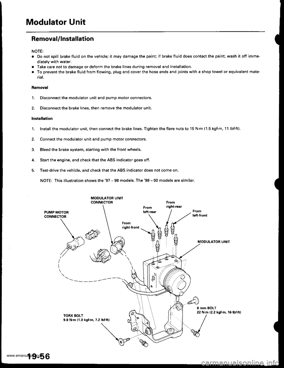
Modulator Unit
Removal/lnstallation
NOTE:
. Do not spill brake fluid on the vehicle; it may damage the painu if brake fluid does contact the paint, wash it off imme-
diately with water.
a Take care not to damage or deform the brake lines during removal and installation.
. To prevent the brakefluidfrom flowing, plug and coverthe hose ends and joints with a shop towel or equivalent mate-
rial,
Romoval
1. Disconnect the modulator unit and Dump motor connectors.
2. Disconnect the brake lines, then remove the modulator unit.
lnstallation
1. Install the modu lator u nit. then con nect the brake lines. Tighten the flare nuts to 15 N.m ( 1.5 kgf.m, 1 1 lbf.ft).
2. Connect the modulator unit and oumo motor connectors.
3. Bleed the brake system, staning with the front wheels.
4. Start the engine, and check that the ABS indicator goes off.
5. Test-drive the vehicle, and check that the ABS indicator does not come on,
NOTE: This illustration shows the '97 - 98 models. The'99 - 00 models are similar.
PUMP MOTORCONNECTOR
MODULATON UNIT\*\
,@
I
TORX EOLT9.8 N,m (1.0 kgf.m.7.2lbf ftl
19-56
www.emanualpro.com
Page 984 of 1395
GLASS RUNCHANNEL
REAR LOWERCHANNEL
\fi\ \\
t\\\\ IIza\\l@'-ua$
REGULATORReplacement, page 20-10
POWER WINDOWMOTOR
k'"""'*^."
OUTER HANOLEReplacement, page 20-8
INNER HANOLE
CYLINDEBPROTECTOR
LATCHPROTECTOR
POWEF
(cont'd)
20-3
@,
,;@
I
POWENwtNDowswtTcH
ACTUATOB
www.emanualpro.com
Page 986 of 1395
OUARTERSEAL
OUARTERGLASSReplacement,page 20-13
-flHiili^'i--_Fffi
POWER WINDOWMOTOR
REAR CHANNEL-\UPPERCOLLAR -.-----_----_-""
trw
page 20 2L
LATCHReplacement,page 20'13
POWEB DOORLOCK ACTUATOB
,6S
REGULATORReplacement, page 20'13
GLASS RUNCHANNEL
FRONT LOWERCHANNEL
STRIKERAdjustment,
l
I
W*
INN€R HANDLE
/ eowea wrruoow
I sYtfcH
s /* /
M-q/-\
flsg
LOCK RODPROTECTORCItr'6,1-
iI
\LOCKCRANK
LATCHPROTECTOB
(cont'd)
20-5
www.emanualpro.com
Page 992 of 1395

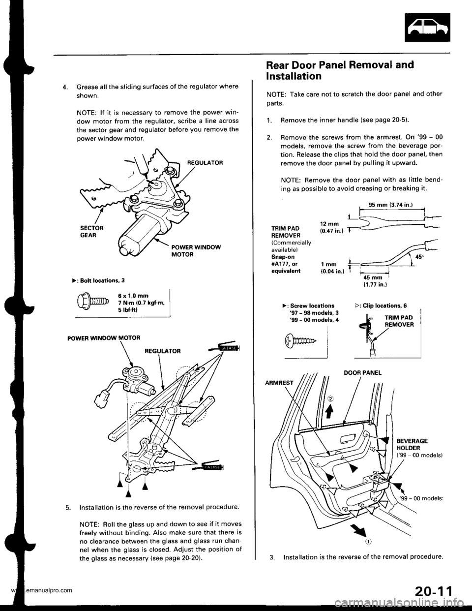
4. Grease all the sliding surfaces of the regulator where
shown.
NOTE: lf it is necessary to remove the power wrn-
dow motor from the regulator, scribe a line across
the sector gear and regulator before you remove the
power window motor.
R€GULATOF
>: Boh locations,3
6x1.0mm7 N.m lo.t kgf.m,5 tbf.ftl
POWER WINOOW MOTOR
REGULATOR
Installation is the reverse of the removal procedure.
NOTEi Rollthe glass up and down to see if it moves
freely without binding. Also make sure that there is
no clearance betlveen the glass and glass run chan
nel when the glass is closed. Adjust the position of
the glass as necessary (see page 20-20).
4
A
m^i
A
Rear Door Panel Removal and
lnstallation
NOTE: Take care not to scratch the door panel and other
parts.
1. Remove the inner handle (see page 20-5).
2. Remove the screws from the armrest. On '99 - 00
models, remove the screw from the beverage por-
tion. Release the clips that hold the door panel, then
remove the door panel by pulling it upward.
NOTE: Remove the door panel with as little bend-
ing as possible to avoid creasing or breaking it.
TBIM PADREMOVER(Commercially
available)Snap-on#4177, orequivalentlmm{0.04 in.)
>: Screw locelions'97 - 98 models. 3'99 - 00 modols, 4
11.77 in.)
DOOB PANEL
ARMREST
o
i
'99 - 00 models:
3. Installation is the reverse of the removal procedure.
\(,1
t_
T r-----/t5 mm I
EEVERAGEHOLDEN('99 00 modelsi
>i Clip locations,6
20-11
www.emanualpro.com
Page 996 of 1395

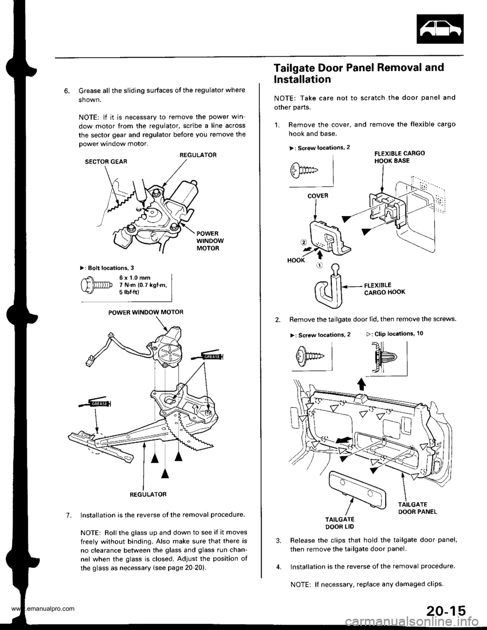
6. Grease all the sliding surfaces of the regulator where
shown.
NOTE: lf it is necessary to remove the power win-
dow motor from the regulator, scribe a line across
the sector gear and regulator before you remove the
power window motor.
REGULATORSECTOR GEAB
POWERwtNDowMOTOR
>: Bolt locations.3
6x1.0mm7 N.m 10.7 kgf.m,5 rbnftl
POWER WINDOW MOTOR
REGULATOR
7. lnstallation is the reverse of the removal procedure.
NOTEr Roll the glass up and down to see if it moves
freely without binding. Also make sure that there is
no clearance between the glass and glass run chan-
nel when the glass is closed. Adjust the position of
the glass as necessary {see page 20 20).
1. Remove the cover,
hook and base.
>: Screw locations.2
Tailgate Door Panel Removal and
lnstallation
NOTE: Take care not to scratch the door panel and
other parts.
and remove the flexible cargo
FLEXIBLE CARGOHOOK BASE
>: CliP locations.
?11 |
HPI,4| |
I
FLEXIBLECARGO HOOK
2. Remove the tailgate door lid, then remove the screws.
>: Screw locations.2
TAILGATEDOOR LIO
Release the clips that hold the tailgate door panel,
then remove the tailgate door panel.
Installation is the reverse of the removal procedure.
NOTE: lf necessary, replace any damaged clips.
3.
@t"
COVER
i
20-15
www.emanualpro.com
Page 1059 of 1395
Rear Hatch Glass
Replacement
CAUTION:
. Put on gloves to protecl your hands.
. Use seal covers to avoid damaging any surfaces.. Do not damage the rear window delogger grid lines
and terminals.
NOTE: An assistant is helpful when removing the rear
hatch glass.
a: Nul locationsAa.4 Ba.4
€ @ i!iff*-"-
Harnoss wiring locations:
REAR WINDOW WIPERMOTOR CONNECTORRemove the rear wiper lowercover (see page 20-99i.
HARNESS 'TRIM
.;=-
8 x 1.25 mm22 N-m l'2.2 kgl.m,'16 tbt fr)
8 x 1.25 mm22N.m l.2.2*ql.m,16 tbf.ft|
Installation is the reverse of the removal orocedure.
NOTE:
. Adjust the rear hatch glass alignment.
. Make sure the connector, terminals and washer tube are connected properly.
. Adjust the aim of the rear window washer nozzle (see page 20-103).
20-78
REAR SPOILER
'--
www.emanualpro.com