Page 1284 of 1395
Power Door Locks
UNDER.HOOD FUSE/FELAY BOX
Circuit Diagram (With Keyless Entry System)
GN TION SW TCHUNDER DASHFUSE/RELAY BOXEATTEFY
@*n'
WHT/GFN
8
ITEYLES--lI TRANSMIT]ER ILr--------
. PASSENGENS DOOR SWITCHES. ]NTEGRATED CONTROL UNIT5
23-124
HORNRELAY
f7
II- GRY
FRONTCEILINGL GHT
Y_o*,,.,,,0-
HATCHGLASSOPENERSOLENO D
HATCH
OPENERswlTcH
f7
I
YEL
L
fIllBl
+BL(
I
G61lG63l
INTEGRATED ICoNTROL UN T I
,Y, I
F",'*-{
.,ufrro I
tl
rthg#,i."J L
T
8!?i"'[:lll',fffi)
BLK
I
I--
G401G402
YEL
8LK
I
G551
DRIVER'SDOOF LOCKswrTcH
UNLOCK
nrrenu @
LOCK
@
KEYLESSDOOs LOCKCONTROL UNIT
BLK
I
G551
--1
www.emanualpro.com
Page 1285 of 1395
UNDER-DASHFUSE/RELAYBOX
Circuit Diagram {Without Keyless Entry System)
IGNTION SWITCHBATTEBY
@**'
FRONTCEILINGTIGHT
V
l_
r-
HATCHGLASSOPENERSWTCH
f7
I
l-J';
tr| oBtvERsI DOOn LOCKACTUATOR
s l-lLocx^l-Tq. l,, | -=tGJ--
+ II Locx IDRIVER'SD00R LOC(SWITCN
KNOB
6 tr.*;lwrr 3-K +wqr-t_t- BLKYEL
ffr
vEL
YEURED
GRNORN
GRNWHT
HORNRELAY
V
BLK
II
I:
G551
23-125
INTEGRATEDCONTROL UNIT
V
IBLU/RED
I
l- 8Lr
IBLU/RED
II
Iupl ,#. L?Vno'::iii^ ( li: ) swrTcHYAil''"',4,.'{yrcLosED
l' tottt
IBLK
II
I':
G()1G402
YEL
t/ |
tFl
?BLK
I
G6l1
UNDER.HOOD FUSEi RELAY 8OX
(Nol used)
LOCK
o
POWERDOOR LOCKCONTROL UNIT
EIGHT REAR00oR LocKACTUATOR
'tl
www.emanualpro.com
Page 1286 of 1395
Power Door Locks
Gontrol Unit Input Test
1. Remove the driver's door panel (see section 20).
2. Disconnect the 18P connector from the control unit.
3. lnspect the connector and socket terminals to be sure they are all marking good contact.
. lf the terminals are bent, loose orcorroded, repairthem as necessary, and recheck the system.
. lf the terminals look OK, make the following input tests at the connector.- lf any test indicates a problem, find and correct the cause, then recheck the system.- lf all the input tests prove OK, the control unit must be faulty; replace it.
BLUGRN/BED GRY YEL WHT/REO WHT/GRN
723,/58
101t12 1131416171E
GRN/WHT I LT
18P CONNECTON
female terminals
23-126
www.emanualpro.com
Page 1287 of 1395

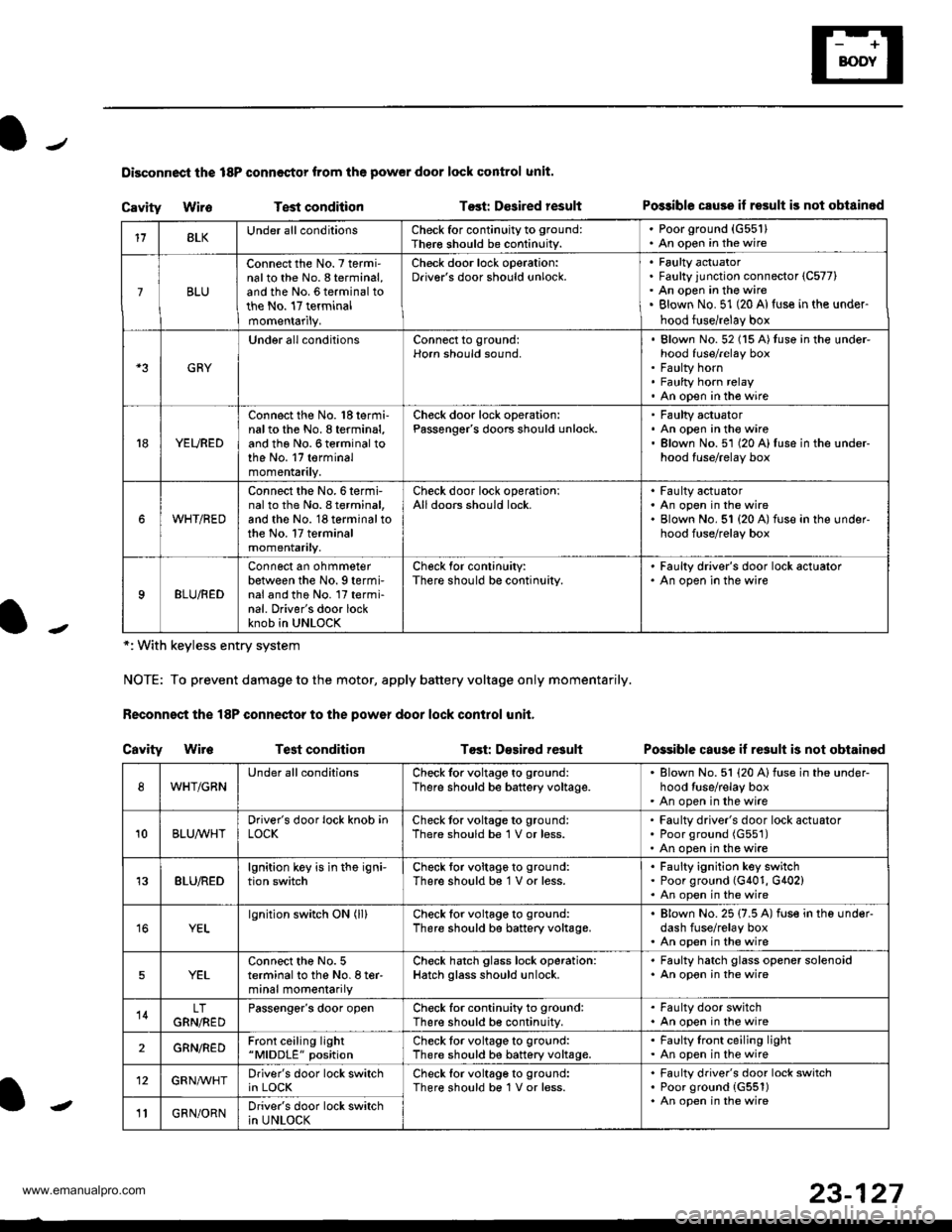
Disconnoci the 18P connestor from the pow€r door lock control unit.
Cavity WireTest conditionTost: Dcsired resultPo$ible csuse il result is not obtainod
Possible cause if result is not obtain€d
*: With keyless entry system
NOTE: To prevent damage to the motor, apply battery voltage only momentarily.
Feconnoct the 18P conneqtor to the power door lock control unit,
Cavity Wir6Test conditionTost: D€sirod result
118LKUnder all conditionsCheck for continuity to ground:
Ther€ should be continuity.
. Poorground (G55'l). An open in the wire
7BLU
Connect the No. 7 termi'nalto the No. 8 terminal,and the No. 6 terminal tothe No. 17 terminalmomentarily.
Check door lock operation:Driver's door should unlock.Faulty actuatorFaulty junction connector (C577)
An open in the wireBlown No. 51 (20 Al{use in the under-
hood fuse/relay box
GRY
Under all conditionsConnect to ground:Horn should sound,Blown No. 52 (15 A)tuso in the under-hood fuse/relay boxFaulty hornFaulty horn relayAn open in tho wire
YEURED
Connect the No. 'l8 termi-nalto the No. 8 terminal,and the No. 6 terminal tothe No. 17 terminalmomentarily.
Check door lock operation:Passenger's doors should unlock.Faulty actuatorAn open in the wireBlown No.51 (20 A)fuse in the under-hood fuse/relay box
WHT/RED
Connect the No.6termi-nal to th6 No. I terminal,and the No. 18 terminal tothe No. 17 terminalmomentarily.
Check door lock operationlAll doors should lock.Faulty actuatorAn open in the wireBlown No. 51 {20 A) fuse in ihe under-hood fuse/relay box
9BLU/RED
Connect an ohmmeterbetween the No. 9 termi-nal and the No. l7 termi-nal. Driver's door lockknob in UNLOCK
Check for conlinuity:There should be continuity.
' Faulty driver's door lock actualor. An open in the wire
WHT/GRNUnder all conditionsCheck for voltage to ground:
There should be battery voltage.Blown No. 51 (20 Alfuse in the under-hood tuse/relay boxAn open in the wire
10BLUAVHTDriver's door lock knob inLOCKCheck tor voltage to ground:There should be 1 V or less.Faulty driver's door lock actuatorPoor ground (G551)
An open in the wire
13BLU/REDlgnition key is in the igni-tion switchCheck tor voltage to ground:
There should b€ 1 V or less.Faulty ignition key switchPoor ground (G401, G402)An open in the wire
YELlgnition switch ON (ll)Check for voltage to ground:
There should be battery voltage.Blown No. 25 (7.5 A) fuse in the under-dash fuse/relay boxAn open in the wire
5YELConnect the No. 5terminal to the No. I ter-minal momentarily
Check hatch glass lock operation:Hatch glass should unlock.
. Faulty hatch glass opener solenoid. An opon in the wire
14LTGRN,NEDPassengor's door openCheck for continuity to ground:There should b€ continuity.
. Fa(llty door switch. An open in the wire
2GRN/R€DFront ceiling light"MlDDLE" positionCheck tor voltage to ground:There should be battery voltage.Faulty lront ceiling lightAn open in the wire
12GRNAr'VHTDriver's door lock switchin LOCKCheck lor voltage to ground:There should be 1V or less.Faulty driver's door lock switchPoor ground {G551)An open in the wire' GRN/ORNDriver's door lock switchin UNLOCK-
23-127
www.emanualpro.com
Page 1292 of 1395
Power Windows
Component Location Index
FRONT PASSCNGER'SWINDOW MOTORTest, page 23-137POWER WINDOW MASTERSWITCH(Has built in control unit)Input Test, page 23-'134Test, page 23-135
RIGHT REAR WINDOWMOTOBTest. page 23-138
FBOI{T PASSENGER'SWI{DOW SWTTCHTest, page 23-138
LEFT REAN WWDOWSwlTCHTest, page 23-137
LEFT REAR WINDOWMOTORTest, page 23-'t38
DRIVER'S WINDOWMOTORTest, page 23-137
RIGHTwtNDow swTcHT6sr, page 23-137
tt
L--JIJJ'JJL J 1J 15-- --------------) ------------ t_.1
--.-\-.--t
\-
23-132
.-
www.emanualpro.com
Page 1294 of 1395
Power Windows
Master Switch Input Test
NOTE: The control unit is built into the power window master switch and only controls driver's door window operations.
1. Remove the master switch, and disconnect the 14P,2? and 1P connectors from the master switch.
2. Inspect the connector and socket terminals to be sure they are all making good contact.
. lf the terminals are bent, loose or corroded, repair them as necessary, and recheck the system,
. lf the terminals look OK, make the following input tests at the connector.- lf a test indicates a problem, find and correct the cause, then recheck the system.- lf all the input tests prove OK, the power window maser switch must be faulty; replace it.
1P CONNECTOR
BLU/ORN RED/BLUYEL/BLK
BLU/YEL RED/YELGRN
GRN/YEL
POWER WINDOW MASTEB SWITCH
GRN/BLK aLu/BLK BLK RED/WHT YEL/GRN YEL
Wire side offemale terminals
RED/BLK
lirP CONNECTOR
23-134
Wire side oIfemale terminals
.-
www.emanualpro.com
Page 1296 of 1395

Power Windows
1.
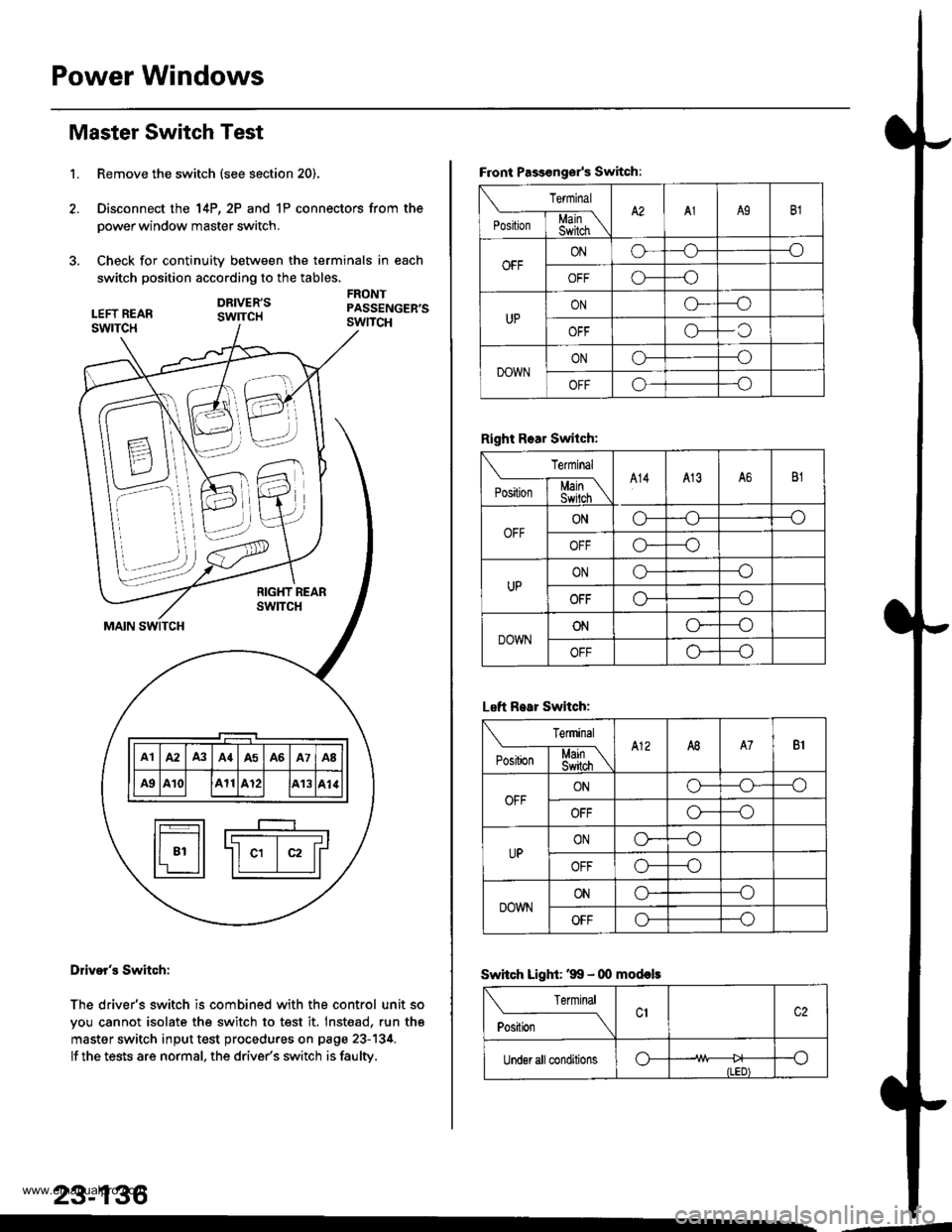
Master Switch Test
Remove the switch (see section 20).
Disconnect the 14P, 2P and 1P connectors from the
power window master switch.
Check for continuity between the terminals in each
switch position according to the tables.
DRIVER'SswrTcH
FRONTPASSENGER'SswncH
B \\N
7-.i::,,,
\\'. )),,
t-_____r-__I F---T-----r-----r----r-----T---------T-----'r Illal lA2 lA3 lA{lA5 lA6 lA7 laB ll
lF#lll ae lA10l lA11lA12l lA13lal.llI r________r_____J t-t___Jl
fr---r-l r----
I t-------- -------r l
ll 81 ll -ll c1 | c2 lrl'r ll ll I llL--:J
Dliver's Switch:
The driver's switch is combined with the control unit so
you cannot isolate the switch to test it. Inst€ad, run th6
master switch input test procedures on page 23-134.
lf the tests are normal. the drive/s switch is faulty.
23-136
--d
F.ont Passongsr's Switch:
rermrnal
'**[ffiA2A1A9B1
OFFONo--_o
o---o
UPONG---o
OFFo-C
DOWNONo---o
OFFo---o
Right Rear Switch:
Terminal
'".'*l-$j[\A14413A6B1
OFFONo---o
OFFo*--o
UPONo---o
OFFo---o
DOWNONo----o
OFFo---o
Left R.ar Switch:
Terminal
e*Li*l$[\A12A8A7B1
OFFONo-o--o
OFFo---o
UPONo----o
OFFo---o
DOWNONo--_o
OFFo---o
Swhch Light: '99 - 00 mod€ls
Terminal
ti.*----_\
Under all conditionso--o
ILED)
www.emanualpro.com
Page 1312 of 1395
Component/Wiring Locations Index -'97 model
SRS INDICATOR LIGHT (ln the gauge assembly)Troubleshooting, page 24-27Gauge assembly, section 23
DASHBOABD w|RE HARNESS
to SBS INDICATOR LIGHT in
DRIVER'S AIBMGReplacement,page 21-87Disposal, page 24-97
To CRUISE CONTROLSET
To DRIVERS AnBAG
ANBAG2P
sBsitAr[ ] nNEssto FROI|T PASSEiIGEB.S
FRONT PASSEITGER'S AIRBAGReplacement, pago 24{9Disposal, page 24-97
sns ut{fTGROUND
SES MAIN HAR]GSStosns U nItP OOIIITECTOR
MAIN WIRE HABNESSto DASHBOABD wlRE21P
SRS MAIN HABNESSto UNOEB-DASHFUSE/BELAY BOX2P CONNECTOR
GOf$ECrOn PPIlBLr( 8R t
MEMORY ERASE SIGNALIMES) CONNECTOR I2PI[GRY. GRYI or twHT, BLr.l
GAUGE ASSEMBLY5P
HARNESS
SRS MAIN HARNESSto MAINWIRE HARNESS3P OONNECTOR
24-15
www.emanualpro.com