1997 HONDA CR-V air con
[x] Cancel search: air conPage 1272 of 1395
Rear Window Defogger
Function Test
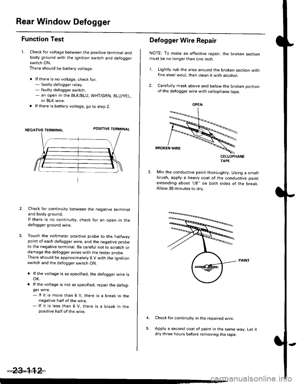
1. Check for voltage between the positive terminal andbody ground with the ignition switch and defoggerswitch ON.
There should be battery voltage.
. lf there is no voltage. check for:- faulty defogger relay.- faulty defogger switch.- an open ,n the BLK/BLU, WHT/GRN, BLU/YEL,
or BLK wire.
. lf there is battery voltage, go to step 2.
POSITIVE TERMINAL
Check for continuity between the negative terminaland body ground.
lf there is no continuity, check for an open in thedefogger ground wire.
Touch the voltmeter positive probe to the halfwaypoint of each defogger wire, and the negative probe
to the negative terminal. Be careful not to scratch ordamage the defogger wires with the tester probe.There should be approximately 6 V with the ignitionswitch and the defogger switch ON.
. lf the voltage is as specified, the defogger wire isoK.
. lf the voltage is not as specified, repair the defog-ger wire.- lf it is more than 6 V, there is a break in thenegative half of the wire.- lf it is less than 6 V, there is a break in thepositive half of the wire.
23-112
Defogger Wire Repair
NOTE: To make an effective repair, the broken sectionmust be no longer than one inch.
1. Lightly rub the area around the broken section withfine steel wool, then clean it with alcohol.
2. Carefully mask above and below the broken portionof the defogger wire with cellophane tape.
CELLOPHANETAPE
Mix the conductive paint thoroughly. Using a smallbrush, apply a heavy coat of the conductive paint
extending about 1/8" on both sides of the break.Allow 30 minutes to dry.
Check for continuity in the repaired wire.
Apply a second coat of paint in the same way. Let itdry three hours before removing the tape.
5,
OPEN
www.emanualpro.com
Page 1274 of 1395
Wipers/Washers
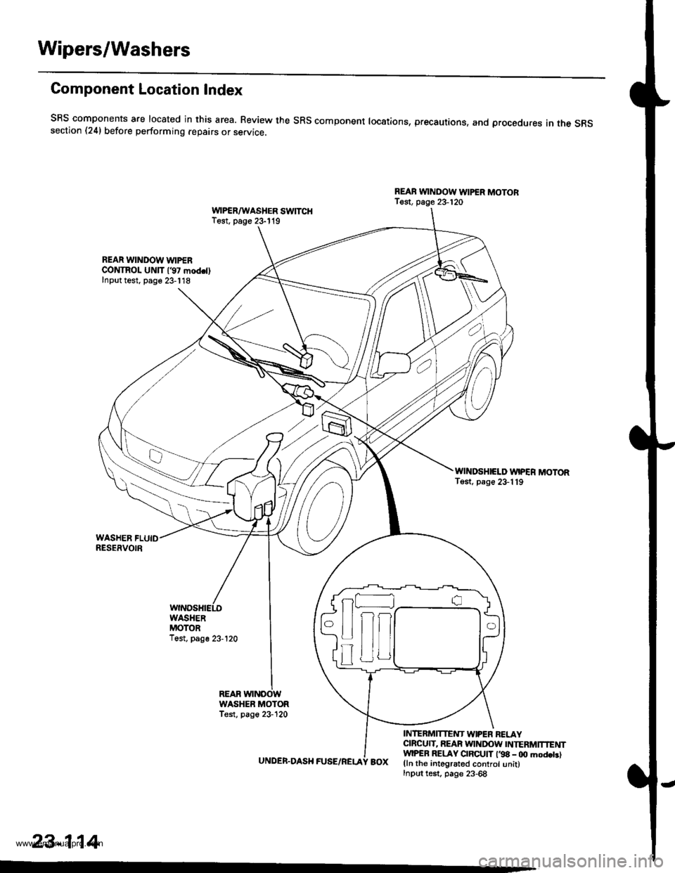
Component Location Index
SRS components are located in this area. Review the SRs component locations, precautions, and procedures in the s6ssection (24) before performing repairs or service.
REAB WINDOW WIPER MOTOBT€st, page 23-120WPSR/WASHER SWITCHTest. page 23- l't9
REAR WINDOW WIPERCONTROL UNlT 137 mod.llInput test. page 23-118
WINDSHIELD WIPER MOTORTost, page 23-119
UNDER.DASH FUSE/RELA
INTERMITTENT W|PEN RELAYCIBCUIT, REAR WINDOW INTERMTNENTwlPER RELAY CIBCUIT l'98 - 0O mod.t.lBOX (ln the integrated control unit)Input test, page 23-68
23-114
-
n
tff
www.emanualpro.com
Page 1278 of 1395
Wipers/Washers
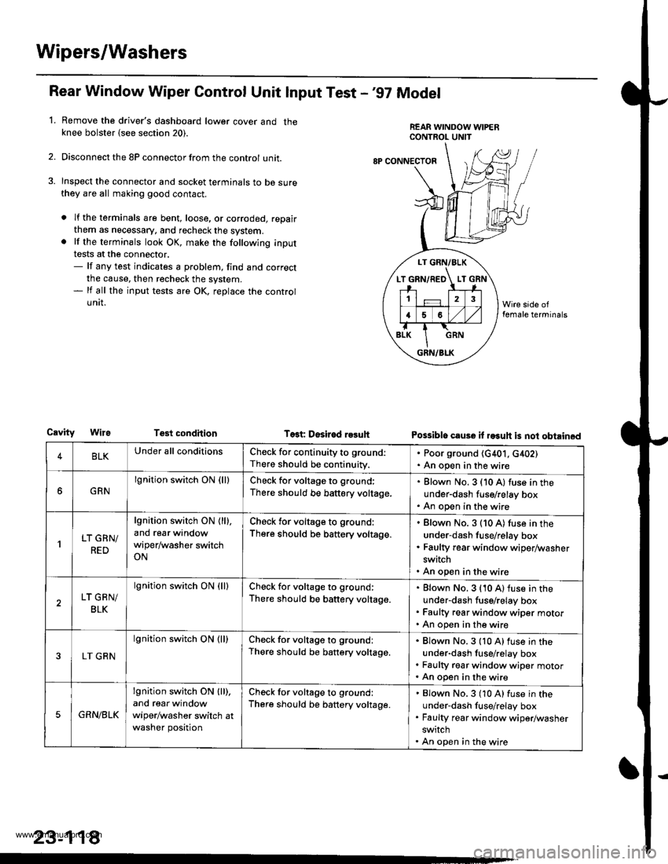
Rear Window Wiper Gontrol Unit lnput Test -'97 Model
Remove the driver's dashboard lower cover and theknee bolster {see section 20).
Disconnect the 8P connector from the control unit.
Inspect the connector and socket terminals to be surethey are all making good contact.
a lf the terminals are bent, loose, or corroded, repair
them as necessary. and recheck the system.. lf the terminals look OK, make the following input
tests at the connector.- lf any test indicates a problem, find and correct
the cause, then recheck the system.- lf all the input tests are OK, replace the control
UNII.
1.
LT GRN/BLK
T GRN/RED LT
12
16
GRN/BLK
8P CONNECTOF
CavityTest condhion Test Desir€d r93uhPossible cause il rasuh is not obtained
4BLKUnder all conditionsCheck for continuity to ground:
There should be continuity.
. Poor ground (G401, c402). An open in the wire
GRN
lgnition switch ON (lllCheck for voltage to ground;
There should be battery voltage.
Blown No. 3 (10 A) fuse in the
under-dash fuse/relay box
An open in the wire
'lLT GRN/
RED
lgnition switch ON ( ll),
and rear window
wiper/washer switch
ON
Check for voltage to ground:
There should be battery voltage.
Blown No. 3 (10 A) fuse in the
under-dash fuse/relay box
Faulty rear window wiper/washer
switch
An open in the wire
LT GRN/
BLK
lgnition switch ON (lllCheck for voltage to ground;
There should be battery voltage.
Blown No. 3 {10 A) fuse in the
under-dash fuse/relay box
Faulty rear window wiper motor
An open in the wire
LT GRN
lgnition switch ON (ll)Check for voltage to ground:
There should be battery voltage.
Blown No.3 {10 A)fuse in the
under-dash fuse/relay box
Faulty rgar window wiper motorAn open in the wire
5GRN/BLK
lgnition switch ON lll),
and rear window
wiper/washer switch at
washer position
Check for voltage to ground:
There should be battery voltage.
Blown No.3 (10 A) fuse in the
under-dash fuse/relay box
Faulty rear window wiper/washer
switch
An open in the wire
23-118
www.emanualpro.com
Page 1286 of 1395
Power Door Locks
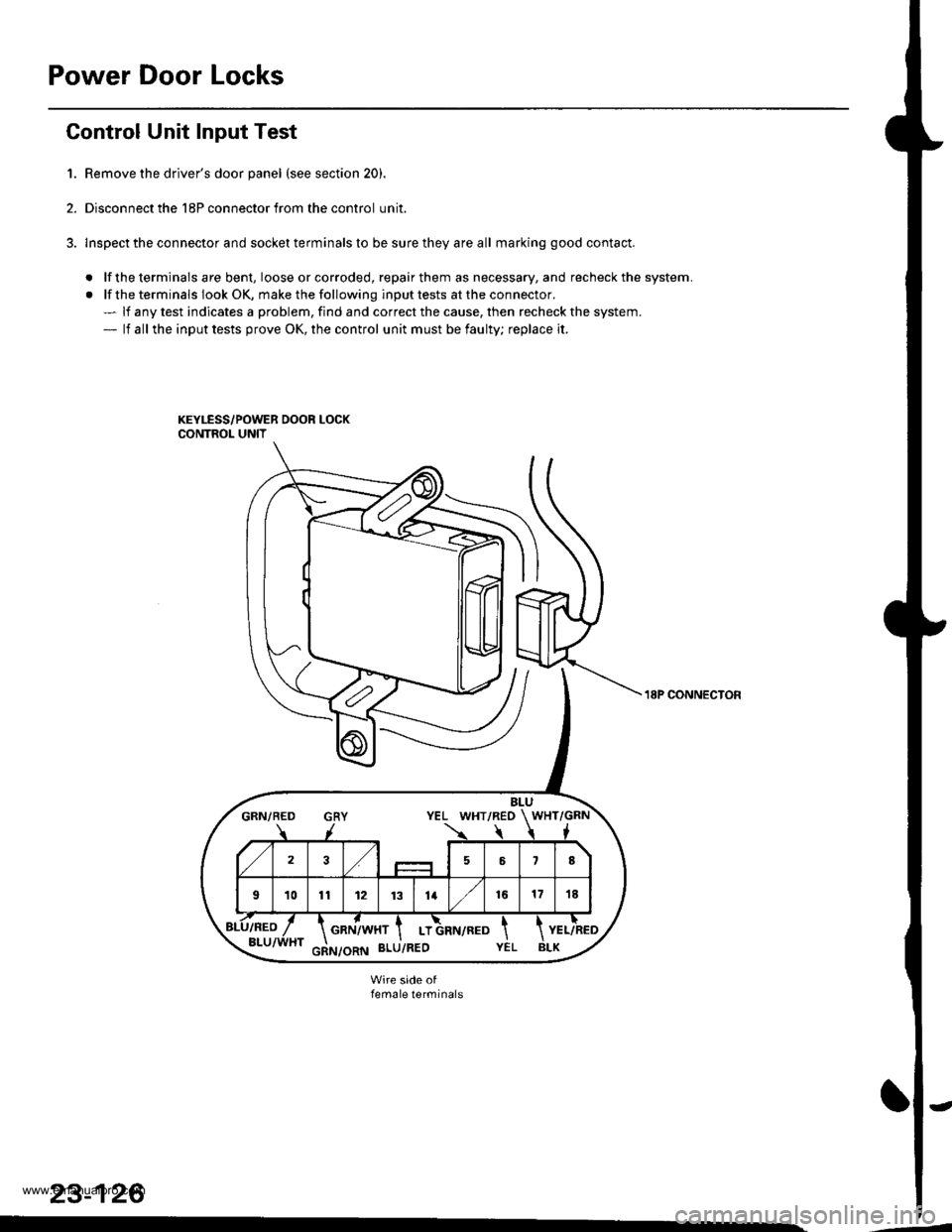
Gontrol Unit Input Test
1. Remove the driver's door panel (see section 20).
2. Disconnect the 18P connector from the control unit.
3. lnspect the connector and socket terminals to be sure they are all marking good contact.
. lf the terminals are bent, loose orcorroded, repairthem as necessary, and recheck the system.
. lf the terminals look OK, make the following input tests at the connector.- lf any test indicates a problem, find and correct the cause, then recheck the system.- lf all the input tests prove OK, the control unit must be faulty; replace it.
BLUGRN/BED GRY YEL WHT/REO WHT/GRN
723,/58
101t12 1131416171E
GRN/WHT I LT
18P CONNECTON
female terminals
23-126
www.emanualpro.com
Page 1294 of 1395
Power Windows
Master Switch Input Test
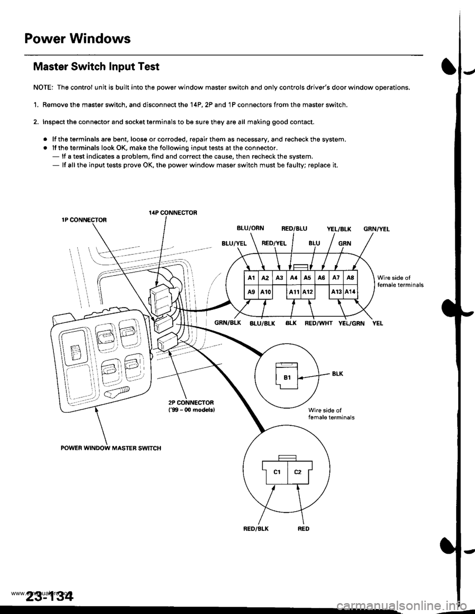
NOTE: The control unit is built into the power window master switch and only controls driver's door window operations.
1. Remove the master switch, and disconnect the 14P,2? and 1P connectors from the master switch.
2. Inspect the connector and socket terminals to be sure they are all making good contact.
. lf the terminals are bent, loose or corroded, repair them as necessary, and recheck the system,
. lf the terminals look OK, make the following input tests at the connector.- lf a test indicates a problem, find and correct the cause, then recheck the system.- lf all the input tests prove OK, the power window maser switch must be faulty; replace it.
1P CONNECTOR
BLU/ORN RED/BLUYEL/BLK
BLU/YEL RED/YELGRN
GRN/YEL
POWER WINDOW MASTEB SWITCH
GRN/BLK aLu/BLK BLK RED/WHT YEL/GRN YEL
Wire side offemale terminals
RED/BLK
lirP CONNECTOR
23-134
Wire side oIfemale terminals
.-
www.emanualpro.com
Page 1301 of 1395
JFront Seat Belt RePlacement
SRS components are located in this area. Review the SRS
component locations, precautions, and procedures in this
section (24) before performing repairs or service ('98 - 00
models).
CAUTION: Check the front seat bslts for damago. and
replaco thom if necessary. Be careful not to damage
them during removal and in3tallation'
Front scat bolt:
1. Make sure you have the anti-theft code for the
radio, then write down the frequencies for the pre-
set buttons.
2. Disconnect the negative battery cable, and wait at
least three minutes before beginning work.
3. Slide the front seat forward fully.
4. Bemove (see section 20):
. Center pillar lower trim Pane
. Kick oanel
. Front side trim
5. '97 model: Remove the upper anchor cover and the
lower anchor caP.'98 - oO models: Remove the upper anchor cover
and pull the lower anchor cover back.
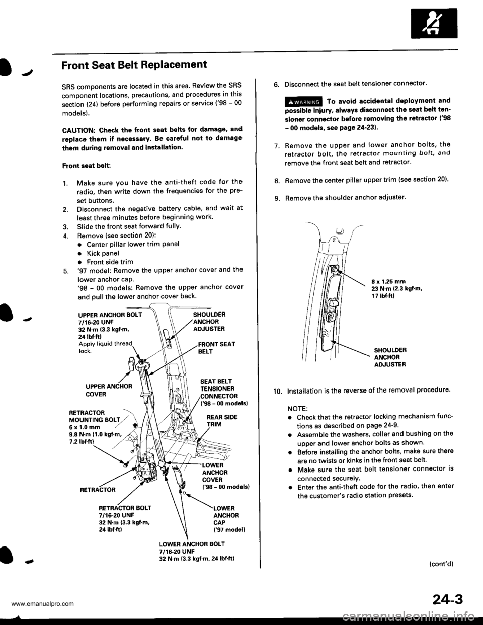
UPPEN ANCHOR BOLT
7/1&20 UNF32 N.m (3.3 kgt'm.24 tbf.ft)
SHOULDERANCHORADJUSTER
Apply liquid threadlock.
9.8 N.m (1.0 kgt.m,?.2 tbtft)
UPPERCOVER
RETRACTORMOUNTING BOLTZ,,Gx1.0mm ./
SEAT BELTTENSIONER
{'98 - 0o modols)
REAR SIDE
ANCHORCOVERl'98 - 00 models)
ANCHORCAP('97 modell
RETRACTOR BOLT7/1&20 UNF32 N.m 13.3 kgt m,24 tbt.ft)
LOWER ANCHOR BOLT?,/1&20 UNF32 N.m {3.3 kgf.m, 2,1 lbf.ftl
o.Disconnect the seat belt tensiongr connector.
@ To avoid accidontal deployment and
possibte inlury, always disconnect the soat bsh ton-
sion€r connoctor bofore rsmoving th6 retractor l'98
- 00 modsls, se€ pa ge 21-231 .
Remove the uDDer and lower anchor boits, the
retractor bolt, the retractor mounting bolt, and
remove the front seat belt and retractor.
Remove the center pillar upper trim (see section 20).
Remove the shoulder anchor adjuster.
7.
9.
8.
I x 1.25 mm23 N.m 12.3 kgt.m,1? tbf.ft)
SHOULDERANCHORADJUSTER
10. lnstallation isthe reverse of the removal procedure.
NOTE:
Check that the retractor locking mechanism func-
tions as described on Page 24-9.
Assemble the washers, collar and bushing on the
uooer and lower anchor bolts as shown.
Eefore installing the anchor bolts, make sure there
are no twists or kinks in the front seat belt.
Make sure the seat belt tensioner connector ls
connected securelv.
Enter the anti-theft code for the radio, then enter
the customer's radio station presets
(cont'd)
24-3
www.emanualpro.com
Page 1307 of 1395
Inspection
SRS components ale located in this area. Review the
SRS component locations, precautions, and procedures
in this section (24) before preforming repairs or service
('98 - 00 models).
!!!@ To avoid accidontal deployment and possi-
6i6-'rnpry. att"ays aisconnsct th€ seat beh tensioner con-
n€ctor belore removing tho retrastor {.98 - 00 modols, seo
page2+231.
Rgtlastor Insgection
1. Before installing the retactor, check that the seat belt
can be pulled out freely
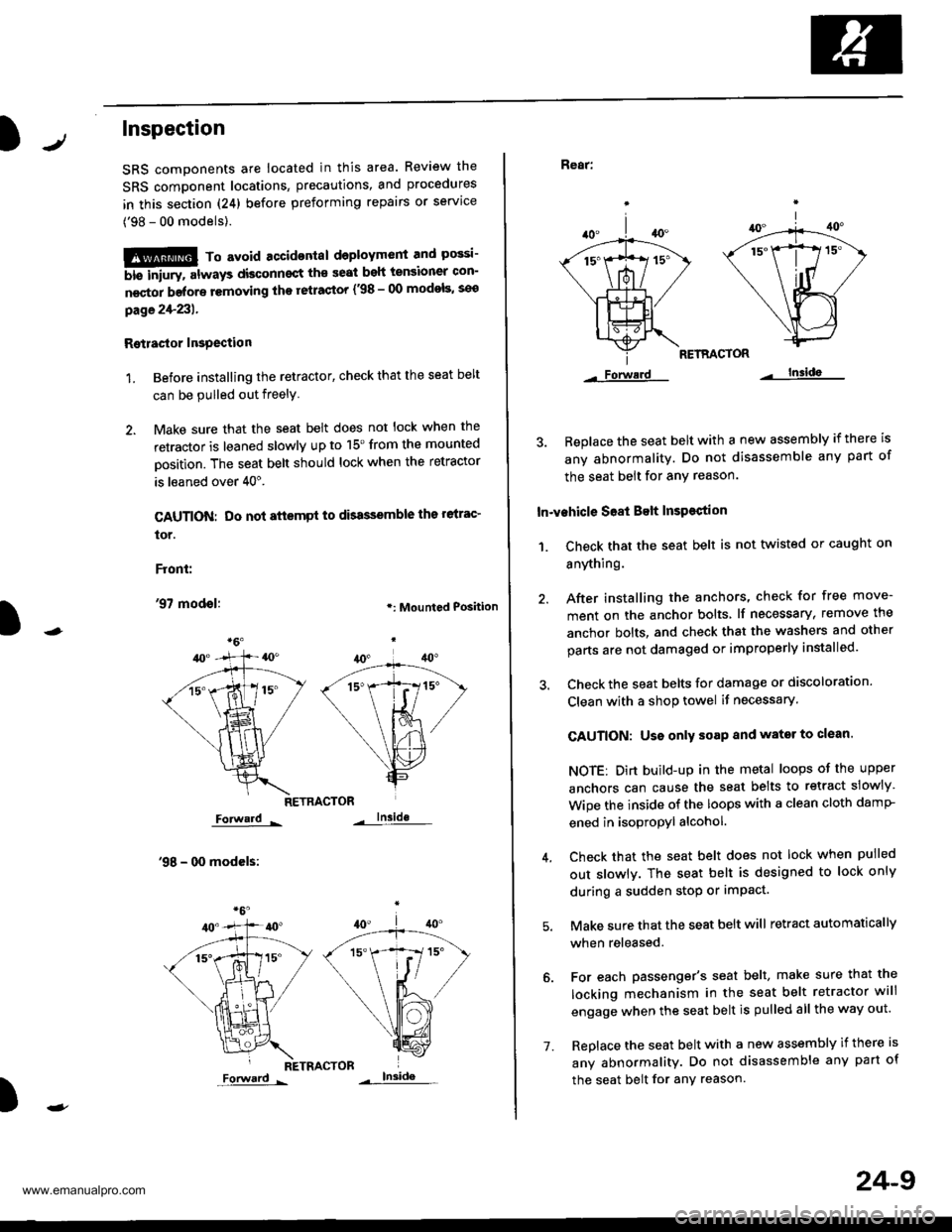
2. Make sure that the seat belt does not lock when the
retractor is leaned slowly up to 15'from the mounted
Dosition. The seat belt should lock when the retractor
is leaned over 40".
CAUTION: Do not attsmpt to dbassemble ths relrac'
tor.
Front:
'97 modol:.: Mounted Position
RETRACTOR
Forward -
'98 - 00 modcls:
lnside
RETRACTOR
)
Forward -
'1.
24-9
Rear:
RETRACTOR
Forwerd lnsida
3. Beplace the seat belt with a new assembly if there is
any abnormality. Do not disassemble any part of
the seat belt for any reason.
In-vehicle S68t Belt InsPestion
1. Ch€ck that the seat belt is not twisted or caught on
anything.
40.
/A
\|_t-.
*1ix
\/
Lls=
Forwerd
After installing the anchors, check for free move-
ment on the anchor bolts lf necessary, remove the
anchor bolts, and check that the washers and other
parts are not damaged or improperly installed.
Check the seat belts for damage or discoloration.
Clean with a shop towel if necessary.
CAUTION: Uso only soap and wator to clean.
NOTE: Dirt build-up in the metal loops of the upper
anchors can cause the seat belts to retract slowly
Wipe the inside of the loops with a clean cloth damP
ened in isopropyl alcohol.
Check that the seat belt does not lock when pulled
out slowlv. The seat belt is designed to lock only
during a sudden stop or impact.
Make sure that the seat belt will retract automatically
when released.
For each passenger's seat belt, make sure that the
locking mechanism in the seat belt retractor will
engage when the seat belt is pulled all the way out.
Replace the seat belt with a new assembly if there is
any abnormality. Do not disassemble any part of
the seat belt for any reason.
www.emanualpro.com
Page 1310 of 1395
)
Supplemental Restraint System (SRS)
Special Tools .."....."" 24-14
Component/Wring Location
lndex - '97 model ..........'.." '.....""" 24-15
Component/Wiring Location
lndex - '98 - 00 models ..............." 24-16
Description .'.........."'.24'17
Circuit Diagram .........24'14
Precautions/Procedures
General Precautions ......".."'........... 24-19
Airbag/Seat Belt Tensioner
Handling and Stolage ....''........... 24-19
SRS Unit Precautions ...............'...... 24-20
lnspeciion After Deployment .......'.24'20
)
with Built-in Short Contact '...'....24-21
Spring-loaded Lock Connectors .."' 24-22
BackProbing SPring-loaded Lock
Conneetors ,.......24-22
Disconnecting the Airbag Connectors and
the Seat Beh Tensioner
Connectors ....'....24-23
Steering-lelated Precautions .......... 24-25
Troubleshooting
Self -diagnostic Procedures ............. 24-26
Reading the DTC .................. .....".."' 24'26
Erasing the DTC Memory ................24-28
Troubleshooting lntermittent
Faifures "'...........24'24
Diagnostic Trouble Gode {DTC}
Chart -'97 model ....""....... "......24-29
Diagnostic Trouble Gode (DTCI
Chart -'98 - 00 models ............. 24-31
SRS Indicator Light Wire
Connections ','," 24'33
Ff owcharts ....-........24'34
Driver's Airbag
Repf acement ..'......21'87
Front Passenger's Airbag
Repfacement .....'.',24'AS
Gable Reel
Replacement .......'.24-91
SRS Unit
Replacement .........24-95
Airbag/Seat Belt Tensioner
Disposaf .................24'97
)-e
www.emanualpro.com