Page 123 of 1395

Timing Belt
Removal
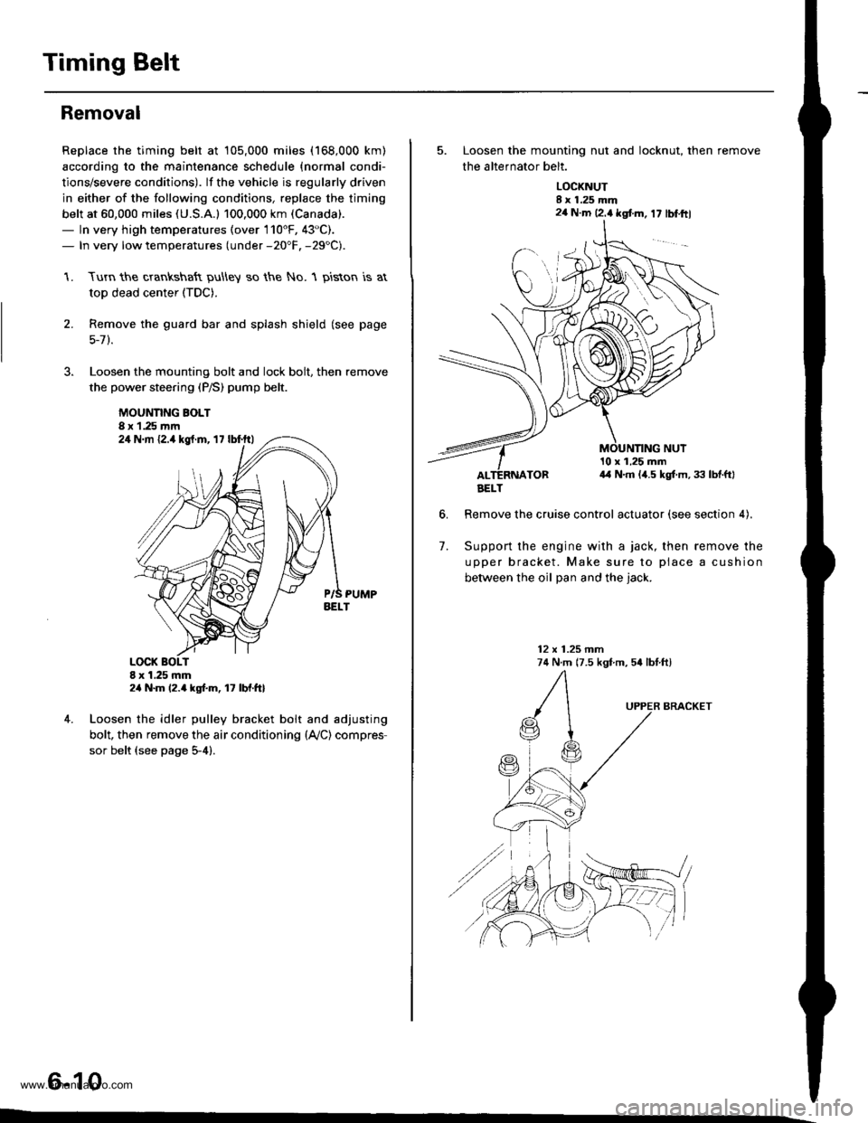
Replace the timing belt at 105,000 miles (168,000 km)
according to the maintenance schedule {normal condi-
tions/severe conditions). lf the vehicle is regularly driven
in either of the following conditions, replace the timing
belt at 60,000 miles (U.S.A.l 100.000 km (Canada).
- ln very high temperatures (over 110'F, 43"C).- In very low temperatures (under -20"F. -29"C).
Turn the crankshaft pu\ley so the No. 1 piston is at
top dead center (TDC).
Remove the guard bar and splash shield (see page
5-7 ).
Loosen the mounting bolt and lock bolt. then remove
the power steering (P/S) pump belt.
MOUNNNG BOLT8 x 1.25 rnm
1.
2.
,l
4. Loosen the idler pulley bracket bolt and adjusting
bolt, then remove the air conditioning (lVC) compres
sor belt (see page 5-4).
6-10
24 N.m {2.4 kgt.m, 17 lbf.ftl
24 N.m 12.4 kgf.m, lt lbf.ftl
5. Loosen the mounting nut and locknut, then remove
the altefnator belt.
LOCKNUTI x 1.25 mm2a N.m 12.4 kgt m, 17 lblftl
6.
10 x 1,25 mm4,1 N.m (,1.5 kgt m, 33 lbtftl
Remove the cruise control actuator (see section 4).
Support the engine with a jack, then remove the
upper bracket. Make sure to place a cushion
between the oil Dan and the iack.
12 x 1.25 mm74 N.m (7.5 kgf m, 54 lbtftl
7.
BRACKET
AELT
www.emanualpro.com
Page 128 of 1395
-?E
handling a metal gasket. take care not to fold it or damage the contact surface.
Prior to reassembling, clean all the parts in solvent, dry them and apply lubricant to any contact parts.
CYLINDER HEAD BOLT11 x 1.5 mm85 N.m {8.7 kgf.m,6:} lbf.ft)Tightening, page 6'30.Apply engine oilto the threads.VALVEKEEPERS
\
END PIVOT BOLT63 N.m 16.4 kgl m, 46 lbf.ft)
EXHAUSY VALVESEALReplace.
EXHAUST VALVEGUIDEInspection, page 6-25Replacem6nt, page 6-25Reaming, page 6-27
10 x 1.25 mm4,0 N.m {i1.5 kgf.m.33 rbf.ft)
GASKETReplace.
OIL CONTROLORIFICEClean.
EXHAUST VALVESPRING
SPRING BETAINER
INTAKE VALVESPRING
INTAKE VALVE SEALReplace.
VALVE SPRINGSEAT
INTAKE VALVEGUIDE
Removal, page 6-16Warpage, page 6 27Valve seat reconditioning,page 6 28Installation, page 6-30
EXHAUSTVALVE
INTAKE VALVERemoval, page 6-23Installation, page 6-29
CYLINDER HEAO
HEAD
O.RINGReplace.
8 x 1.25 mm24 N.m (2.4 kgf.m,17 tbf.ft)
DOWEL PIN
6-15
www.emanualpro.com
Page 130 of 1395
8. Remove the throttle cable by loosening the locknut,
then slip the cable end out of the throttle linkage.
Take care not to bend the cable when removing it.
Always replace any kinked cable with a new one.
'97 - 98 modols:
'!X, - 00 modob:
9. Relieve fuel pressure (see section 11).
@ Do not smoke while working on the
fuel systom. Ko€p opon flame or sparks away from
ths work area. Drain fuol only into an approved
containgr.
'10, Remove the evaporative emission (EVAP) control
canister hose and fuel feed hose.
CANISTER HOSE
{cont'd)
6-17
www.emanualpro.com
Page 132 of 1395

13. Remove the upper radiator hose, heater hose and
water bypass hose.
WATER BYPASS
UPPEBRADIATORHOSE
17
HEATERHOSE
Remove the engine wire harness connectors and
wire harness clamps from the cylinder head and the
intake manifold.
o Four fuel injector connectors
. Engine coolant temperature (ECT) sensor con-
neclor
. Radiator fan switch connector
. Coolant temperature gauge sendlng unlt connec-
tor
. Throttle position sensor connector
. Manifold absolute pressure {MAP) sensor con-
nector
Primary heated oxygen sensor (primary HO2S)
connector
ldle air control (lAC) valve connector
Distributor connector
Remove the spark plug caps and distributor from the
cylinder head.
Remove the cruise control actuator (see section 4).
Support the engine with a jack, then remove the
upper bracket. Make sure to place a cushion
between the oil pan and the iack (see page 6-10).
a
18. Remove the cylinder head cover.
19. Inspect the timing belt (see page 6-9).
CYLINDER
(cont'd)
6-19
www.emanualpro.com
Page 143 of 1395

Cylinder Head
Installation
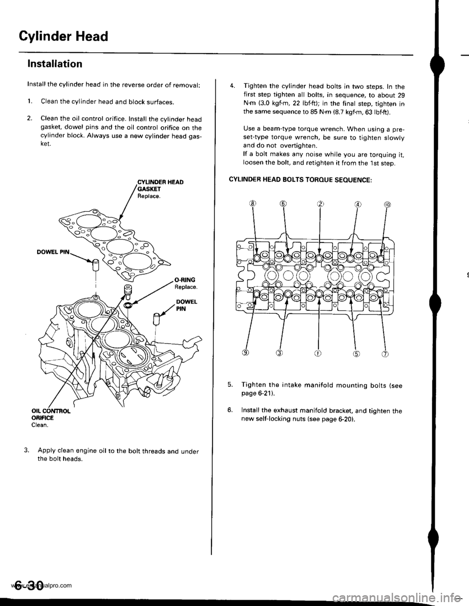
Installthe cylinder head in the reverse order of removal:
1. Clean the cylinder head and block surfaces.
2. Clean the oil control orifice. Install the cylinder headgasket, dowel pins and the oil control orifice on thecylinder block. Always use a new cylinder head gas-ket.
CYLII{DER HEADGASKETR€place.
DOWEL PIN
O.RINGRoplace.
DOWELPIN
OIL CONTBOLORIFICEClean.
Apply clean engine oil to the bolt threads and underthe bolt heads.
4. Tighten the cylinder head bolts in two steps. In thefirst step tighten all bolts, in sequence, to about 29
N.m {3.0 kgf.m,22 lbf.ft); in the finat step, tighten inthe same sequence to 85 N.m (8.7 kgf.m,63 lbf.ft).
Use a beam-type torque wrench. When using a pre-
set-type torque wrench, be sure to tighten slowly
and do not overtighten.
lf a bolt makes any noise while you are torquing it,loosen the bolt, and retighten it from the 1st step.
CYLINDER HEAD BOLTS TOROUE SEOUENCE:
Tighten the intake manifold mounting bolts (see
page 6-21).
Install the exhaust manifold bracket. and tighten thenew self-locking nuts (see page 6-20).
6-30
www.emanualpro.com
Page 173 of 1395
lllustrated Index
OIL CONTROLORIFICE
OIL PUMPOverhaul, page 8-8Removal/lnspection, page 8 IApply liquid gasket tomating surface of engine block.
'99 - 00 models:KNOCK SENSOR31 N.m {3.2 kgf.m.23 lbl.ft)
ENGINE OIL PRESSURE SWITCH18 N.m {1.8 kgtm, 13lbl.ft)1/8 in. BSPT (British StandardPipe Taper) 28 Threads/inch.Use proper liquid sealant.
O-RING
DOWEL PIN
6x1.0mm9.8 N.m (1.0 kgf.m,7.2 tbl.ft)
8 x 1.25 mm24 N.m 12.4 kgf.m,17 tbf.ft)
BAFFLE PLATE
kgtm,7.2 lbtftl
Replace.
6x1.0mm9.8 N.m 11.0 kgf m,7.2 tbf.ftl
OIL PANGASKETReplace.
OIL PANBeferto page 7 22when installing.
6x1.0mm12 N.m 11.2 kglm,8.7 lblftl
WASHEBReplace.
DRAIN BOLT4,1N.m {,1.5 kgf'm,33 lbf ft)Do not overtighten.
'-- /o-RrNG ,/ Reptace.
\^ ./
v,/
U
6x1.0mm9.8 N.rn {1.0
SCREEN
8-3
www.emanualpro.com
Page 191 of 1395
Engine Hose Connections:
FAST IDLE THERMOVALVE (A/T onlyl
IDLE AIR CONTROLIIAC}VALVE
TEF BYPASSHOSE
THERMOSTATHOUSING
CONNECTINGPIPE
VALVE
HOSES
10-3
www.emanualpro.com
Page 193 of 1395
Engine Coolant Refilling and Bleeding
1. Slide the heater lemperature control lever to maxi
mum heat.
Make sure the engine and radiator are cooi to the
touch.
2. Remove the radiator caP.
3. Loosen the drain plug, and drain the coolant.
4. Remove the drain bolt from the cylinder block.
DRAIN PLUG
DRAIN BOLT78 N.m {8.0 ksl.m, 58 lbtft}
10-5
6.
7.
Apply liquid gasket to the drain bolt threads, then
reinstall the bolt with a new washer and tighten it
securely.
Tighten the radiator drain plug securely.
Remove, drain and reinstall the reservoir' Fill the
tank halfway to the MAX mark with water, then up
to the MAX mark with antitreeze.
(cont'd)
www.emanualpro.com