1997 HONDA CR-V piston ring
[x] Cancel search: piston ringPage 165 of 1395
Crankshaft Oil Seal
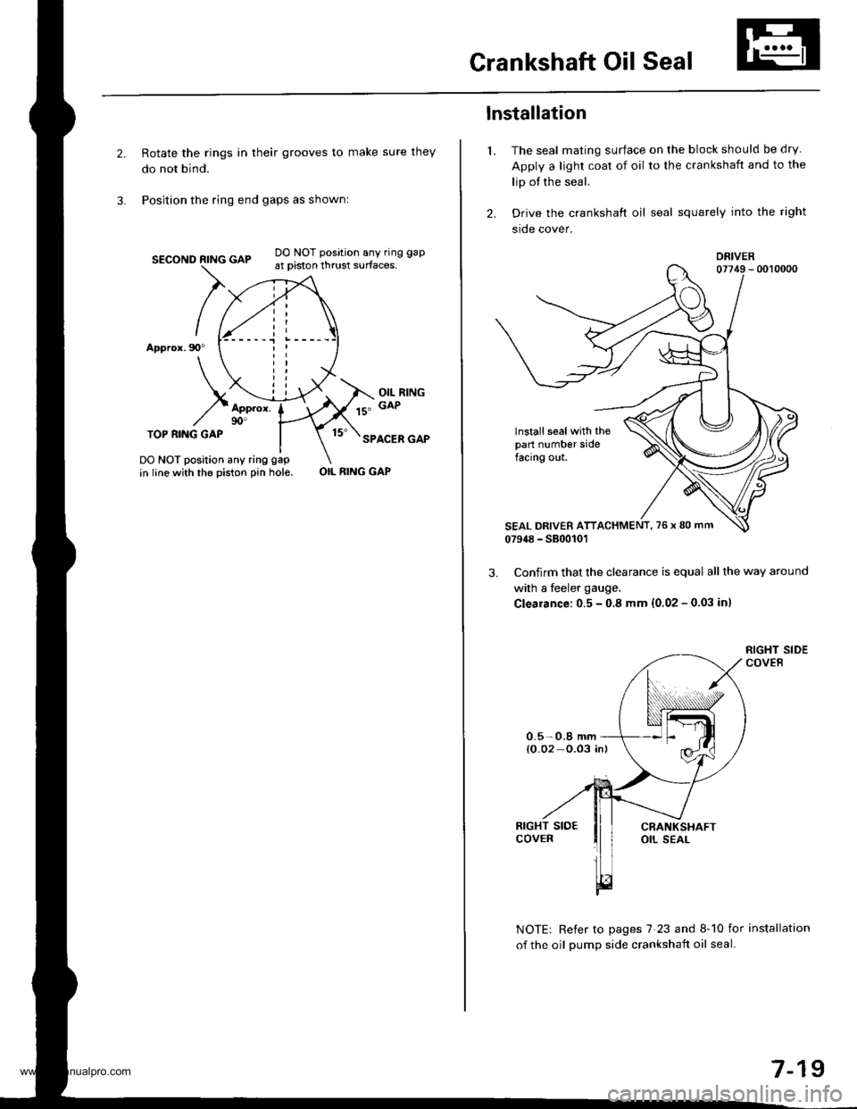
Rotate the rings in their grooves to make sure they
do not bind.
Position the ring end gaps as shownl
SECOND RING GAP
Appror.90"
DO NOT position any ring gap
at piston thrust surfaces,
OIL RINGGAPAppror.90'TOP RI.IIG GAPSPACER GAP
DO NOT position any ring gap
in line with the piston pin hole.OIL RING GAP
1.
lnstallation
The seal mating surface on the block should be dry
Apply a light coat of oil to the crankshaft and to the
lip of the seal.
Drive the crankshaft oil seal squarely into the right
sroe cover.
DRIVER
lnstall seal with thepart number sidefacing out.
Confirm that the clearance is equal all the way around
with a feeler gauge.
Clearance:0.5 - 0.8 mm {0.02 - 0.03 inl
NOTE| Refer to pages 7 23 and 8-10 for installation
of the oil oumD side crankshait oil seal.
0.5-0.8 mm{O.02 0.03 in)
7-19
www.emanualpro.com
Page 166 of 1395
PistonsCrankshaft
Installation
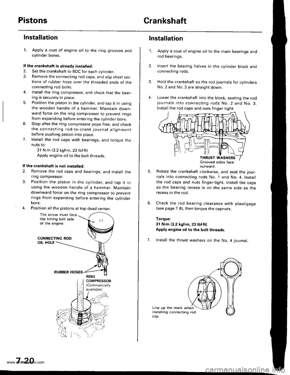
1. Apply a coat of engine oil to the ring grooves andcylinder bores.
It the crankshaft is already installed.
2. Set the crankshatt to BDC for each cylinder.3. Remove the connecting rod caps, and slip short sections of rubber hose over the threaded ends of theconnecting rod bolts.
4. lnstall the ring compressor, and check that the bear-ang is securely in place.
5. Position the piston in the cylinder, and tap it in usingthe wooden handle of a hammer. Maintain down-ward force on the ring compressor to prevent ringstrom expanding before entering the cylinder bore.6. Stop after the ring compressor pops free, and checkthe connecting rod-to-crank journal alignmentbefore pushing piston into place.
7. Install the rod caps with bearings, and torque theNUIS IO:
31 N.m (3.2 kgf.m,23 tbf.ft)
Apply engine oil to the bolt threads.
lf the crankshaft is not installed:
2. Remove the rod caps and bearings, and install theflng compressor.
3. Position the piston in the cylinder, and tap it inusing the wooden handle of a hammer. Maintaindownward force on the ring compressor to prevent
rings from expanding before entering the cylinderoore,
4. Position all the pistons at top dead center.
The arrow must facethe timing belt sideof the engine.
CONNECTING ROOOIL HOLE
RUBBER HOSES
7 -20
\-\
3.
4.
1.
6.
Installation
Apply a coat of engine oil to the main bearings androd bearings.
Insert the bearing halves in the cylinder block andconnect|ng rods.
Hold the crankshaft so the rod journals for cylindersNo.2 and No. 3 are straight down.
Lower the crankshaft into the block, seating the rodjournals into connecting rods No.2 and No.3.Install the rod caps and nuts finger tight.
outward.
Rotate the crankshaft clockwise, and seat the jour
nals into connecting rods No. 1 and No. 4, Install
the rod caps and nuts finger-tight. Install the capsso the bearing recess is on the same side as therecess an the rod.
Check the rod bearing clearance with plastigage(see page 7 8). then lorque the capnuts.
Torque:
3l N.m 13.2 kgf.m, 23 lbt.ftl
Apply engine oil to the bolt thleads.
5.
7. Install the thrust washers on the No. 4 journal.
Line up the mark wheninstalling connecting rodcap.
www.emanualpro.com
Page 431 of 1395
Clutch Pedal
Adiustment
NOTE:
. To check the clutch interlock switch and clutch
switch, see section 23.
. The clutch is self-adjusting to compensate for wear.
CAUTION: lf there is no clearance bstwa€n the mas-
ter cylinder piston and push rod, ths roloase bearingis held againsi the diaphragm spring, which canresuh in clutch slippage or other clutch probloms.
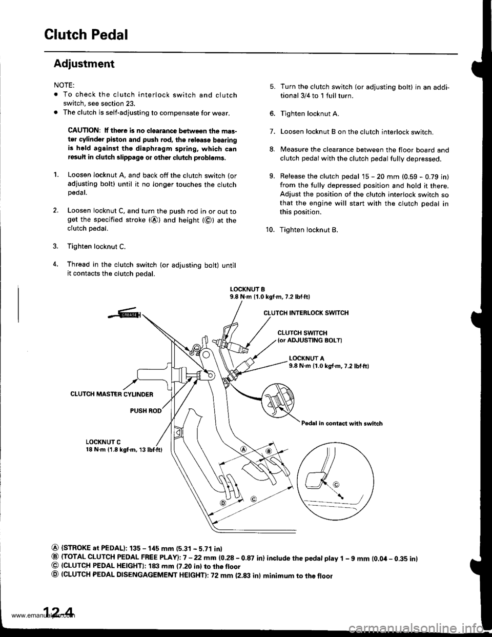
1. Loosen locknut A, and back off the clutch switch (or
sdjusting bolt) until it no longer touches the clutchpeoar.
2. Loosen locknut C, and turn the push rod in or out toget the specified stroke (@) and height (@) at theclutch oedal.
3. Tighten locknut C.
4. Thread in the clutch swirch (or adjusting bolt) untilit contacts the clutch oedal.
7.
5.
8.
q
Turn the clutch switch {or adjusting bolt} in an addi-
tional 3/4 to 1 full turn.
Tighten locknut A.
Loosen locknut B on the clutch interlock switch.
Measure the clearance between the floor board and
clutch pedalwith the clutch pedal fully depressed.
Release the clutch pedal 15 - 20 mm (0.59 - 0.79 in)
from the fully depressed position and hold it there,Adjust the position of the clutch interlock switch sothat the engine will start with the clutch pedal in
this position.
Tighten locknut B.10.
LOCKNUT B9.8 N.m 11.0 kgf.m, 7.2 lbf.ftl
CLUTCH INTERLOCK SWITCH
CLUTCH SWTTCH{or ADJUSTING BOLTI
L(rcKNUT A9.8 N.m {1.0 kg{.m,7.2 lbf.ftl
CLUTCH MASTER CYLINDER
PUSH ROD
Pedal in contact with swhch
LOCKNUT C18 N.m (1.8 kgf.m, 13lbtftl
@ {STROKE at PEDAL): 135 - 1its mm (5.31 - 5.71 in}
@ (TOTAL CLUTCH PEDAL FREE PLAY)i7 -22mm (0.28-0.87 in) inctude the pedat ptay 1 - 9 mm (0.0it- 0.35 inl@ (GLUTC,H PEDAL HE|GHTI: ltxt mm (7.20 inl ro rhe ftoor
o (CLUTCH PEDAL DTSENGAGEMENT HEtcHTl: 72 mm {2.txt inl minimum to the floor
\,/a_-_--/
12-4
www.emanualpro.com
Page 519 of 1395

Description
General Operation
The Automatic transmission is a 3-element torque converter and triple-shaft electronically controlled unit which provides 4
speeds forward and 1 reverse speed The unit is positioned in line with the engine'
There are two tvoes of automatic transmission on CR-V; the four-wheel drive (4WD) model ('97 - 00)' and the front-wheel
drive (2WD) model ('98 - 00).
Toroue Converter, G€ars, and Clutches
The torque converter consists of a pump. turbine. and stator assembly in a single unit. The torque converter is connected to
the engine crankshatt. These parts turn together as a unit as the engine turns. Around the outside of the torque converter is
a ring gear which meshes with the starter pinion when the engine is started. The torque converter assembly serves as a fly-
wheel while transmitting power to the transmission mainshaft.
The transmission has three parallel shafts: the mainshaft. the countershaft, and the sub-shaft. The mainshaft is in line with
the engine crankshaft. The mainshaft includes the 1st, 2nd. and 4th clutches, and gears lor 3rd,2nd,4th. reverse and 1st
(3rd gear is integral with the mainshaft, while reverse gear is integral with the 4th gear). The countershaft includes the 3rd
clutch and gears for 3rd,2nd, 4th, reverse, 1st, and park. Reverse and 4th gears can be locked to the countershaft at its cen-
ter, providing 4th gear or reverse, depending on which way the selector is moved. The sub-shaft includes the lst-hold
clutch and gears for lst and 4th.
The gears on the mainshaft are in constant mesh with those on the countershaft and sub-shaft. When certain combinations
of gears are engaged by the ctutches, power is transmitted from the mainshaft to the countershaft to provide E, D!, tr, tr,
and E position ('97 - 98 models). and E. E, E, and E position ('99 - 00 models)'
Electlonic Control
The electronic controt system consists of the Powenrain Control Module (PCM), sensors, a linear solenoid, and four
solenoid valves. Shifting and lock-up are electronically controlled for comfortable driving under all conditions. The PCM is
located below the dashboard, under the kick panel on the passenger's side.
Hydraulic Control
The valve bodies include the main valve body, the secondary valve body, the regulator valve body, the servo body, and
the lock up valve body. They are bolted to the torque converter housing. The main valve body contains the manual valve,
the 1-2 shift valve, the 2nd orifice control valve. the CPB {Clutch Pressure Back-up) valve, the modulator valve, the servo
control valve. the relief valve, and ATF pump gears. The secondary valve body contains the 2-3 shift valve, the 3-4 shift
valve, the 3,4 orifice control valve. the 4th exhaust valve and the CPC (Clutch Pressure Control) valve. The regulator valve
bodv contains the pressure regulator valve, the torque converter check valve, the cooler relief valve, and the lock-up con-
trol valve. The servo body contains the servo valve which is integrated with the reverse shift tork, and the accumulators
The lock-up valve body contains the lock-up shift valve and the lock-up timing valve. The linear solenoid and the shift con-
trol solenoid valve Ay'B are bolted to the outside of the transmission housing, and the lock-up control solenoid valve Ay'B is
bolted to the outside of the torque converter housing. Fluid trom the regulator passes through the manual valve to the
various control valves. The clutches receive fluid from their respective feed pipes or internal hydraulic circuit
ShiftControl Mechanism
input from various sensors located throughout the vehicle determines which shift control solenoid valve the PCM will acti-
vate. Activating a shift control solenoid valve changes modulator pressure, causing a shift valve to move. This pressurizes
a line to one of the clutches. engaging that clutch and its corresponding gear. The shift control solenoid valves A and B are
controlled by the PCM.
Lock-up Mechanism
tn E! position (,97 - 98 modets) and in E position ('99 - O0 models), in 3rd and 4th, and in Del position in 3rd ('97 - 98
models) and in El position with Over,Drive (O/D) is OFF (by pressing rhe O/D switchl in 3rd ('99 - 00 models), pressurized
fluid is drained from the back of the torque converter through a fluid passage, causing the lock-up piston to be held
against the torque converter cover, As this takes place, the mainshaft rotates at the same speed as the engine crankshaft.
Together with hydraulic control, the PcM optimizes the timing of the lock-up mechanism The lock-up valves control the
range of lock-up according to lock-up control solenoid valves A and B, and the linear solenoid. When lock-up control
solenoid valves A and B activate, the modulator pressure changes. The lock-up control solenoid valves A and B and the
linear solenoid are controlled by the PCM.
{cont'd)
14-3
www.emanualpro.com
Page 555 of 1395
Lock-up System
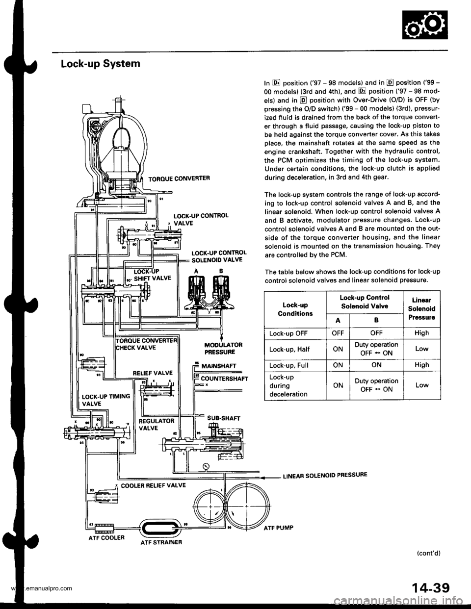
TOROUE CONVERTER
In E position ('97 - 98 models) and in E position ('99 -
OO models) (3rd and 4th), and E position ('97 - 98 mod-
els) and in E position with Over-Drive (O/D) is OFF (by
pressing the O/D switch) ('99 - 00 models) (3rd), pressur-
ized fluid is drained from the back of the torque convert-
er through a fluid passage, causing the lock-up piston to
be held against the torque converter cover, As this takes
Dlace, the mainshaft rotates at the same speed as th8
engine crankshaft. Together with the hydraulic control,
the PCM optimizes the timing of the lock-up system.
Under certain condltions. the lock-up clutch is appli€d
during deceleration, in 3rd and 4th gear.
The lock-up system controls the range of lock-up sccord-
ing to lock-up control solenoid valves A and B, and ths
linear solenoid. When lock-up control solenoid valves A
and B activate. modulator pressure changes. Lock-up
control solenoid valves A and B are mounted on the out-
side of the torque converter housing, and the linear
solenoid is mounted on the transmission housing. They
are controlled bv the PCM.
The table below shows the lock-up conditions for lock-up
control solenoid valves and linear solenoid pressure.
LINEAR SOLENOID PRESSURE
(cont'd)
LOCK.UP CONTROL' VALVE
LOCK.UP CONTROLSOLENOID VALVE
AB
MODULATORPf,ESSURE
MAINSHAFT
COUNTERSHAFT
SUB.SHAFT
Lock-up
Conditions
Lock-up Conirol
Solenoid valveLinaal
Solenoid
PrgssulsAB
Lock-up OFFOFFOFFHigh
Lock-up, HalfONDuty operation
OFF - ONLow
Lock-up, FullONONHigh
Lock-up
during
deceleration
ONDuty operation
OFF - ON
RELIEF VALVE
LOCK'UP TIMINGVALVE
COOLER RELIEF VALVE
ATF COOLERATF STRAINER
ATF PUMP
14-39
www.emanualpro.com
Page 556 of 1395
Description
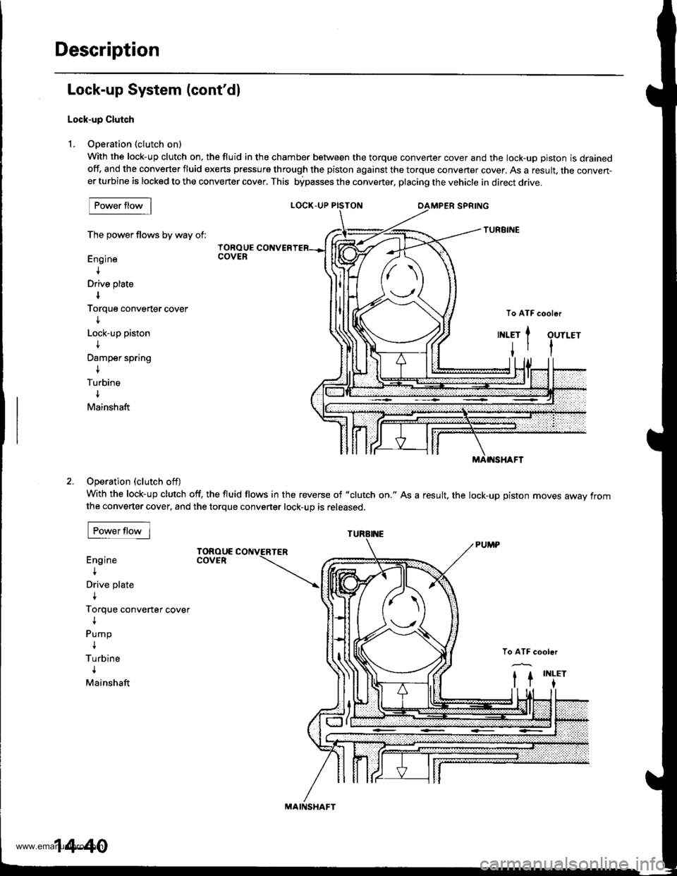
Lock-up System (cont'dl
Lock-up Clutch
L Ooeration (clutch on)
With the lock-up clutch on, the fluid in the chamber between the torque convener cover and the lock-uD oiston is drainedoff, and the converter fluid exerts pressure through the piston against the torque converter cover, As a result, the conven-er turbine is locked to the converter cover. This bipasses the converter, placing the vehicle in direct drive.
LOCK,UP PISTON
The power flows by way of:
Engine
+
Drive plate
Torque converter cover
I
Lock-up piston
t
Damper spring
{
Turbine
Mainshaft
IOROUECOVER
Operation (clutch off)
With the lock-up clutch off, the fluid flows in the reverse of "clutch on." As a result, the lock-up piston moves away fromthe converter cover, and the torque converter lock-up is released.
Engine
I
Drive plate
{
Torque converter cover
{
Pump
I
Turbine
{
Mainshaft
TOROUECOVER
To ATF cooler{(1\\n1INLET
t
Jtl
ort
MAIf{SHAFT
MAII{SHAFT
14-40
www.emanualpro.com
Page 672 of 1395

Symptom-to-Com ponent Chart
Hydraulic System (cont'd)
NOTES
See flushing procedure, page l4-264 and 265,
BSet idle rpm in gear to specified idle speed. lf still no good, adjust motor mounts as outlined in enginesection of this manual.
clf the large clutch piston O-ring is broken, inspect the piston groove for rough machining.
Dlf the clutch pack is seized or is excessively worn. inspect the other clutches fot wear, and check the orificecontrol valves, CPC valve, and linear solenoid for free movement.
lf the linear solenoid is stuck, inspect the clutches for wear.
lf the 1-2 shift valve is stuck closed. the transmission will not upshift. lf stuck open, the transmission hasno lst gear.
Hlf the 2nd orifice control valve is stuck, inspect the 2nd and 3rd clutch Dacks for wear.
lf the 3-4 orifice control valve is stuck, inspect the 3rd and 4th clutch packs for wear.
Jlf the clutch pressure control valve is stuck closed. the transmission will not shift out of lst gear.
Klmproper alignment of main valve body and torque converter housing may cause ATF pump seizure. Thesymptoms are mostly an rpm-related ticking noise or a high-pitched squeak.
Llf the ATF strainer is clogged with particles of steel or aluminum, inspect the ATF pump and differentialpinion shaft. lf both are OK and no cause for the contamination is found, replace the torque converter.
Mlf the lst clutch feed pipe guide in the end cover is scored by the mainshaft. inspect the ball bearing forexcessive movement in the transmission housing. lf oK, replace the end cover as it is dented. The o-rinounder the guide is probably worn.
N' Replace the mainshaft if the bushing for the 4th feed pipe is loose or damaged, lf the 4th feed pipe is darrFaged or out of round. replace the end cover.' Replace the mainshaft if the bushing for the l st feed pipe is loose or damaged. lf the 1st feed pipe is dam-aged or out of round, replace it.
oA worn or damaged sprag clutch is mostly a result of shifting the transmission in E!. E, or E positionwhile the wheels rotate in reverse. such as rocking the vehicle in snow.
PInspect the frame for collision damage.
lnspect for damage and wear:
l. Reverse selector gear teeth chamfers.
2. Engagement teeth chamfers of countershaft 4th and reverse gear.
3. Shift fork for scuff marks in center.
4. Differential pinion shaft for wear under pinion gears.
5. Bottom of 3rd clutch for swirl marks.
Replace items 1, 2, 3. and 4 if worn or damaged. lf transmission makes a clicking, grinding, or whirring noise,also replace mainshaft 4th gear, reverse idler gear, and countershaft 4th gear in addition to 1,2, 3, or 4.lf differential pinion shaft is worn, overhaul differential assembly, replace ATF strainer, and thoroughly cjeantransmission, flush torque converter. cooler, and lines,lf bottom of 3rd clutch is swirled and transmission makes gear noise. replace the countershaft and final drivenoear,
Be very careful not to damage the torque converter housing when replacing the main ball bearing. you
may also damage the ATF pump when you torque down the main valve body. This will result in ATF pumpseizure if not detected. Use the Drooer tools.
SInstall the main seal flush with the torque converter housing. lf you push it into the torque converterhousing until it bottoms out, it will block the fluid return passage and result in damage.
www.emanualpro.com
Page 716 of 1395

Servo Body
Disassembly/lnspection/Reassembly
NOTE:
' cleanall parts thoro ugh ly in solvent or ca rbu retor clea ner, a nd dry them with compressed air, Blow out all passages.. Replace the valve body as an assembly if any parts are worn or damaged.. Coat all parts with ATF during reassembly.
ACCUMULATOR COVER
3RO SUB ACCUMULATOR
O-RINGFeplace.
SERVOFORK S
fi,
il
g
1ST ACCUMULATOR PISTON
Replace.
RVO VAL\IRK SHAFT
O.RING
VE/SHIFT
3RD ACCUMULATOR
SPRING SPECIFICATIONS
\_)
SNAP RING
SNAP RING
Unit: mm {in)
@"- -tP
-.t l@SPR|NG RETATNER ,/
No.SpringsStandard lNewl
Wire Dia,o.D.Free LongthNo. of Coil3
o
@J6
@.A
\o,
o
@
@
1st accumuiator spring
4th accumulator spring A
4th accumulator spring B
3rd accumulator spring A
3rd accumulator spring B
2nd accumulator spring C2nd accumulator spring A2nd accumulator spring B
3rd sub accumulator spring
2.1 (0.083)
2.6 {0.102)
2.3 (0.091)
2.8 (0.110)
2.1 (0.083)
2.2 (0.087l-
2.4 (0.094)
r.6 (0.063)
2.7 {0.106)
16.0 (0.6301
17.0 (0.669)'t0.2 t0.402]�
17.5 (0.689)
31.0 (1.220)
14.5 {0.571)
29.0 11.1421
9.0 (0.354)
17.0 (0.669)
89.r (3.508)
88.4 (3.480)
51.6 (2.031)
94.3 (3.713)
38.2 (1.504)
68.0 {2.677)
39.0 fi.535)
20.7 (0.815)
39.0 (1.535)
14.2
13.8
15.9
2.6
13.9
2.9
o.l
6.3
14-200
www.emanualpro.com