1997 HONDA CR-V passenger
[x] Cancel search: passengerPage 574 of 1395
Troubleshooting Procedures
(cont'dl
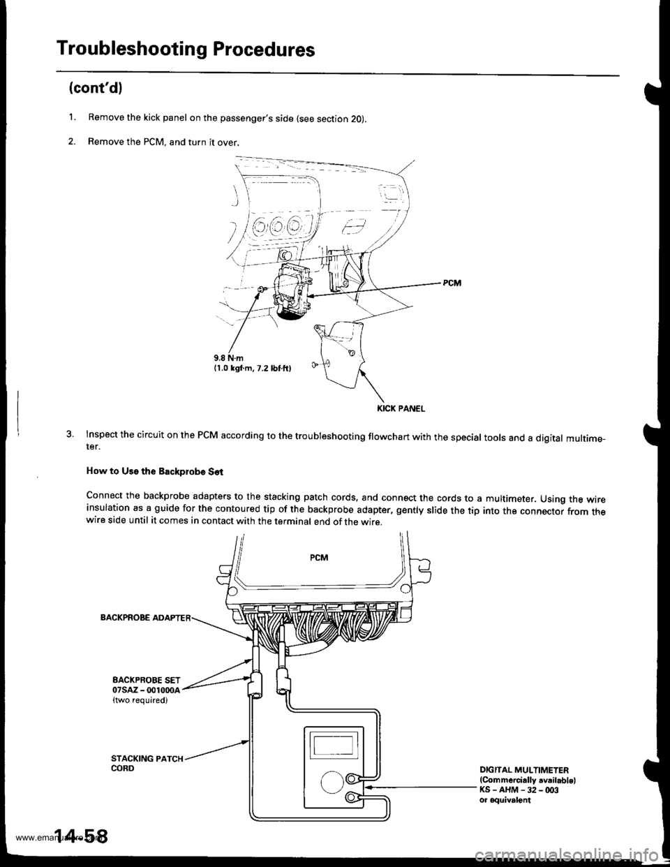
L Remove the kick panel on the passenger's side (see section 2O),
2. Remove the PCM, and turn it over.
Inspect the circuit on the PCM according to the troubleshooting flowchart with the special tools and a digital multime-ter.
How to Use the Backplobe Set
Connect the backprobe adapters to the stacking patch cords, and connect the cords to ainsulation as a guide for the contoured tip of the backprobe adapter, gently slide the tipwire side until it comes in contact with the terminal end of the wire.
multimeter. Using the wire
into the connector from the
BACKPROBE
EACKPROBE SET07sAz - 001000a{two required)
DIGITAL MULTIMETER(Commercially .v.ilablelKS-AHM-32-003ot oquivalont
KICK PANEL
14-58
www.emanualpro.com
Page 846 of 1395

Steering
Special Toofs ............. 17-2
Component Locations
Index ................ ....... 17-3
Troubleshooting
General Troubleshooting ................ 1 7-4
Noise and Vibration ......................... 17-8
Fluid Leaks ............. 17-10
Inspection and Adiustment
Steering Operation .......................... 17-12
Power Assist Check
With Vehicle Parked ....................
Steering Linkage and Gearbox .......
Pump Belt
Rack Guide Adjustment ...................
Fluid Rep|acement ...................,,.,....
Pump Pressure Check .................,,...
*Steering Wheel
Removal ................. 17-18
*Steering Column
Removal/lnstallation ................ ....... 17 -2O
lnspection .............. 17-21
Steering Lock Replacement ............ 17 -22
Power Steering Hoses, Lines
Ffuid Leakage Inspection ................. 17 -23
Repfacement .......... 17-23
Power Steering Pump
Repfacement .......... 17-24
Disassembly ...........17-25
fnspection .............. 17-26
Reassembly ............ 17-28
Power Steering Gearbox
Removal ................. 17-31
Disassembly ........... 17-34
Reassembly ............ 17-40
Ball Joint Boot Replacement .......... 17-50
Installation ............. 17-51
17-12
17-13
17-14
l7-15
17-15
17-16
Disassembly/Reassembly............... 17-18
4'%/b.......... -r'-7--a/
SUPPLEN\EN AL RES\RA(N SYSTES{ (SRS\
This model has an SRS which includes a driver's airbag in the steering wheel hub. a passenger's airbag in the dashboardabove the glove box ('97 - 00 models), and seat belt tensioners in the seat belt retractors ('98 - 00 models). Informationnecessary to safely service the SRS is included in this Service Manual. ltems marked with an asterisk (*) on the contentspage include, or are located near, SBS components. Servicing. disassembling or replacing these items will require specialprecautions and tools, and should only be done by an authorized Honda oearer.
To avoid rendering the SRS inoperative, which could lead to peFonal iniury or death in the event of a sevore trontalcollision. allSRS service work must be performod by an authorized Honda dealer.lmproper service procedurgs, including incorrect removal and installalion of the SRS, could lead to personal iniurycaused by unintontional deployment of th€ airbags {'97 - 00 models), and seat belt tensioners ('98 - 00 modelsl.Do not bump the SRS unit. Otherwise, the system may lail in case ot a collision, or the airbags may deploy when theignition switch is ON (lll.
SRS electrical wiring harnesses are identitied by yellow colof coding. Ralated components are located in the steeringcolumn, front console, dashboard, dashboard lower panel, and in the dashboard above the glove box. Do not use elec-trical test equipment on these cilcuits,
www.emanualpro.com
Page 961 of 1395
Diagnostic Trouble Code (DTC)
Diagnostic Trouble Gode IDTCI Indication
NOTE: This operation can also be done with the Honda pGM Tester.
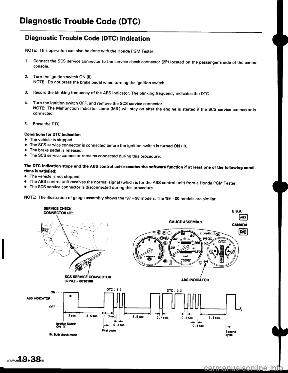
1. Connect the SCS service connector to the service check connector (2P) located on the passenger's side of the centerconsote.
2. Turn the ignition switch ON (ll).
NOTE; Do not press the brake pedal whenturningthe ignition switch.
3 Record the blinking frequency of the ABS indicator. The brinking frequency indicates the DTc.
4. Turn the ignition switch OFF. and remove the SCS service connector.NOTE: The Malfunction Indicator Lamp (MlL) will stay on after the engine is startsd if the SCS seryica connecror rsconnected.
5. Erase the DTC.
Conditions for DTC indication. The vehicle is stopped.. The SCS service connector is connected before the ignition switch is turned ON flt).. The brake pedal is released.. The SCS service connector remains connected during this procedure.
The DTC indication stops and the ABS control unit axecutos tha softwaro lunction if at least one of tho following condi-tions i3 satisfiod:
. The vehicle is not stoooed.. The ABS control unit receives the normal signal (which is for the ABS control unit) from a Honda pGM Tesrer.. The SCS service connector is disconnectod during this procedure.
NQTE: The illustration of gauge assembly shows the '97 - 98 models. The '99 - oo models are similar.
SEFVICE CHECKCONNESTOR I2P}
GAUGE ASSEMBLY
A8S II{DEATOR
u.s.A.
@
CANADA
@
19-38
www.emanualpro.com
Page 962 of 1395
DTC Erasure
NOTE: This operation can also be done with the Honda PGM Tester.
1. Connect the SCS service connector to the service check connector (2P) located on the passenger's side of the center
console.
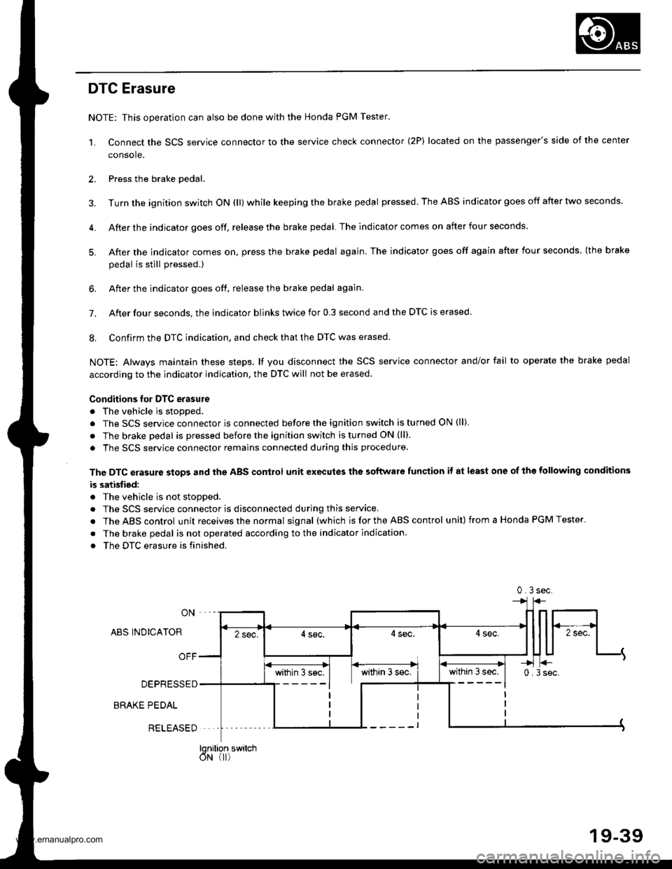
2. Press the brake oedal.
3. Turn the ignition switch ON (ll) while keeping the brake pedal pressed. The ABS indicator goes off after two seconds.
4. After the indicator goes off, release the brake pedal. The indicator comes on after four seconds.
5. After the indicator comes on, press the brake pedal again. The indicator goes off again after four seconds (the brake
oedal is still Dressed.)
6. After the indicator goes off, release the brake pedal again.
7. After four seconds. the indicator blinks twice for 0.3 second and the DTC is erased.
8. Confirm the DTC indication, and check that the DTC was erased.
NOTE: Always maintain these steps. lf you disconnect the SCS service connector and/or fail to operate the brake pedal
according to the indicator indication, the DTC will not be erased.
Conditions for DTC erasure
. The vehicle is stopped.
. The SCS service connector is connected before the ignition switch is turned ON (ll)
. The brake pedal is pressed before the ignition switch is turned ON (ll).
. The SCS service connector remains connected during this procedure.
The DTC erasure stops and the ABS control unit executes the software funqtion it at least one of the following conditions
b satisfied:
. The vehicle is not stopped.
. The SCS service connector is disconnected during this service.
. TheABScontrol unit receives the normal signal (which is for the ABS control unit) from a Honda PGM Tester.
. The brake pedal is not operated according to the indicator indication
. The DTC erasure is finished.
ON
ABS INDICATOR
OFF
DEPRESSED
BRAKE PEDAL
within 3 sec.0.3sec.
0.3sec.
within 3s€c. I within 3 s€c.
lonition switchdN (r)
RELEASED
19-39
www.emanualpro.com
Page 980 of 1395
ABS Control Unit
Pulsers/Wheel
Sensors
Replacement
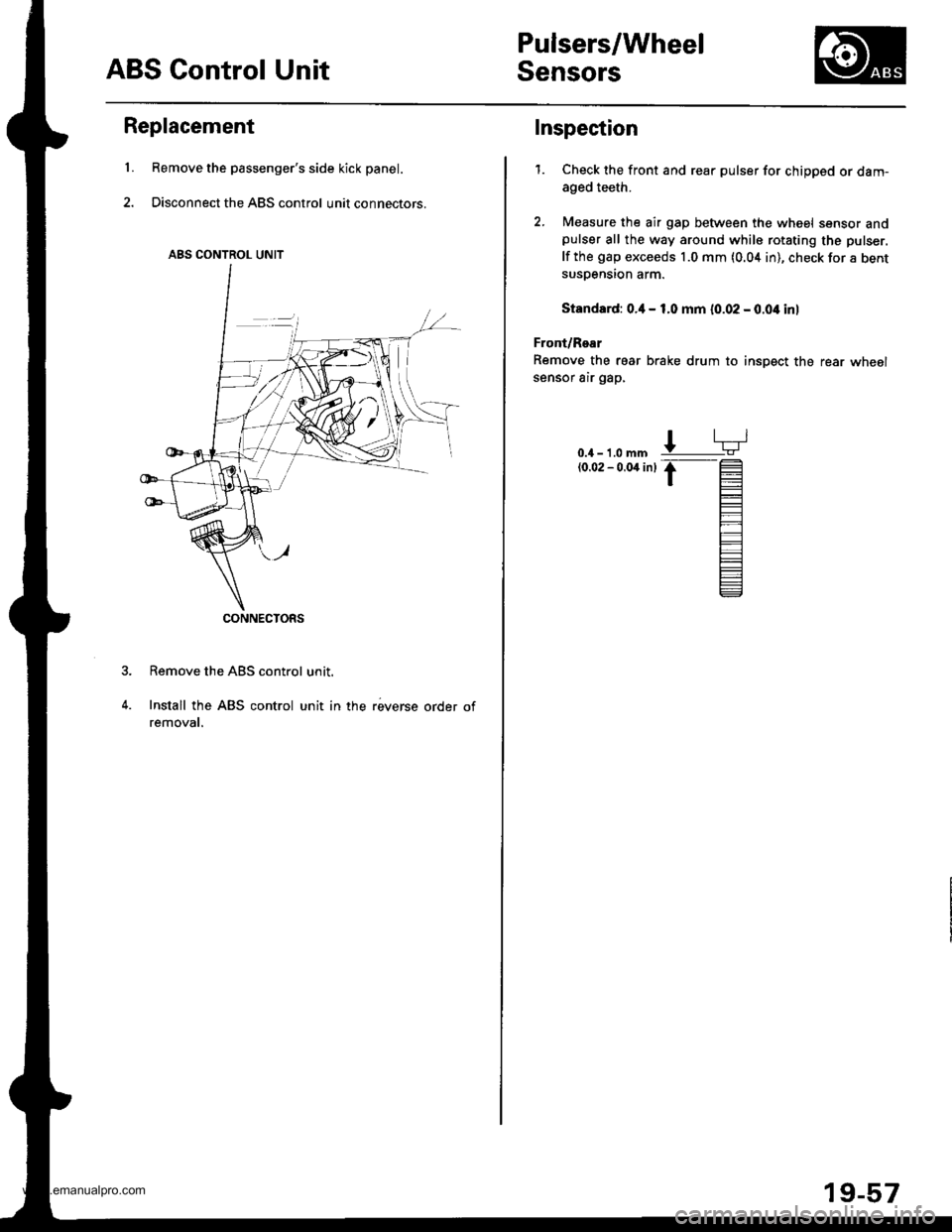
Remove the passenger's side kick panel.
Disconnect the ABS control unit connectors.
Remove the ABS control unit.
Install the ABS control unit in the reverse order ofremovat.
ABS CONTROL UNIT
CONNECTORS
L
Inspection
1.Check the front and rear pulser for chipped or dam-
aged teeth.
Measure the air gap between the wheel sensor andpulser all the way around while rotating the pulser.
lf the gap exceeds 1.0 mm (0.04 in), check for a bentsusDension arm.
Standard: o.il - 1.0 mm 10.02 - 0.04 inl
Front/Rear
Remove the rear brake drum to insDect the rear wheolsensor air gap,
0.4 - 1.0 mm(0.02 - 0.04 inl
19-57
www.emanualpro.com
Page 1025 of 1395
lnterior Trim
Headliner Removal and Installation
CAUTION: When prying with a tlat-tip screwdriver,
wrap it with protective tape to prevent damage.
NOTE:
. Take care not to bend and scratch the headliner.o Be careful not to damage the dashboard and other
interior trim.
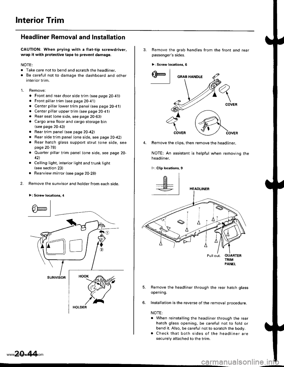
1. Remove:
. Front and rear door side trim (see page 20-41). Front pillartrim (see page 20-41)
. Center pillar lower trim panel (see page 20-41). Center pillar upper trim (see page 20 41). Rear seat (one side, see page 20-63). Cargo area floor and cargo storage bin
{see page 20-43)
. Rear trim panel (see page 20-421
. Rear side trim panel (oneside, see page 20-42l,
. Rear hatch glass support strut (one side, seepage 20-78)
. Ouaner pillar trim panel {one side, see page 20-
42)
. Ceiling light, interior light and trunk light(see section 23)
. Rearview mirror (see page 20-28)
2. Remove the sunvisor and holder from each side.
>: Scaew location3, 4
I
A\"r- |Yr* || -
suNvtsoR
20-44
3. Remove the grab handles from
passenger's sides.
>r Screw locations, 6
the front and rear
ry_l
COVER
4. Remove the clips, then remove the headliner.
NOTE: An assistant is helpful when removing the
headliner.
>: Clip locations,9
HEADLINER
Pullout. OUARTERTRIMPANEL
5. Remove the headliner through the rear hatch glass
openrng.
6. Installation is the reverse of the removal procedure.
NOTE:
. When reinstalling the headliner through the rear
hatch glass opening, be careful not to fold or
bend it, Also, be careful not to scratch the body.. Check that both sides of the headliner are
securely attached to the trim.
www.emanualpro.com
Page 1033 of 1395
Dashboard
Side Air Vent Removal and
lnstallation
CAUTION:
. When prying with a flat-tip screwdriver, wrap it with
protec'tive tape, and apply protcctive tape around the
related parts to provent damage.
. Put on glov€s to protect your hands.
NOTE: Take care not to scratch the dashboard and related
parts.
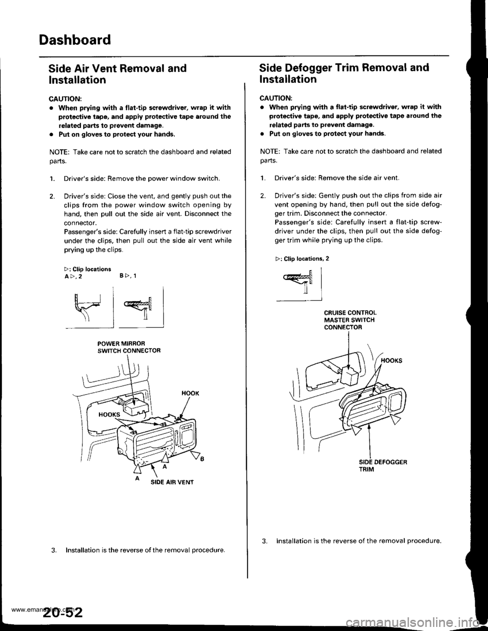
1. Driver's side: Remove the Dower window switch.
2. Driver's side: Close the vent, and gently push out the
clips from the power window switch opening by
hand, then pull out the side air vent. Disconnect the
connector.
Passenger's side: Carefully insert a flat-tip screwdriver
under the clips. then pull out the side air vent while
prying up the clips.
>: Clip locationsA>,2 B>, 1
sl 4
POWER MIRRORSWITCH CONNECTOR
SIDE AIB VENT
3. Installation is the reverse ofthe removal procedure.
20-52
3. Installation is the reverse of the removal procedure.
Side Defogger Trim Removal and
lnstallation
CAUTION:
. when prying whh a flat-tip sctewdriver, wrap it with
protective tape, and apply protectiv€ tape around the
relatgd parts to prevent damagg.
. Put on gloves to protect your hands.
NOTE: Take care not to scratch the dashboard and related
oa rts.
1. Driver's side: Remove the side air vent.
2. Driver's side: Gently push out the clips from side air
vent opening by hand, then pull out the side defog-
ger trim. Disconnect the connector.
Passenger's side: Carefully insert a flat-tip screw-
driver under the clips, then pull out the side defog-
ger trim while prying up the clips.
>: Clip locations, 2
c1
ffil-t
TRIM
www.emanualpro.com
Page 1034 of 1395
Dashboard Removal and Installation
SRS components are located in this area. Review the SRS
component locations, precautions, and procedures in the
SRS section {24) before preforming repairs or service.
CAUTION:
. When prying with a flat-tip screwdriver, wrap h withprotective tap€, and apply protective tape around the
related parts to prevgnt damage.
. Put on gloves to prot€ct your hands.
NOTE:
. An assistant is helpful when removing and installing
the dashboard.
. Take care not to scratch the dashboard, bodv and
other related parts.
1.Make sure you have the anti-theft code for the
radio, then write down the frequencies for the
radio's preset buttons.
Disconnect the negative battery cable. and wait at
least three minutes before beginning work.
Removei
a Driver's dashboard lower cover and knee bolster(see page 20-48)
. Glove box (see page 20-49)
. Lower console cover and center pocket (A/T
model, see page 20-49)
. Center console and center upper pocket (M/T
model, see page 20-47)
. Center dashboard lower cover (see page 20-50)
. Power window switch (see page 20-51)
. Driver's side air vent (see page 20-52)
. Driver's side defogger trim (see page 20-52)
Disconnect the driver's airbag connector, and lower
the steering column (see section 17)
NOTE: To prevent damage to the steering column,
wrap it with a shop towel.
2.
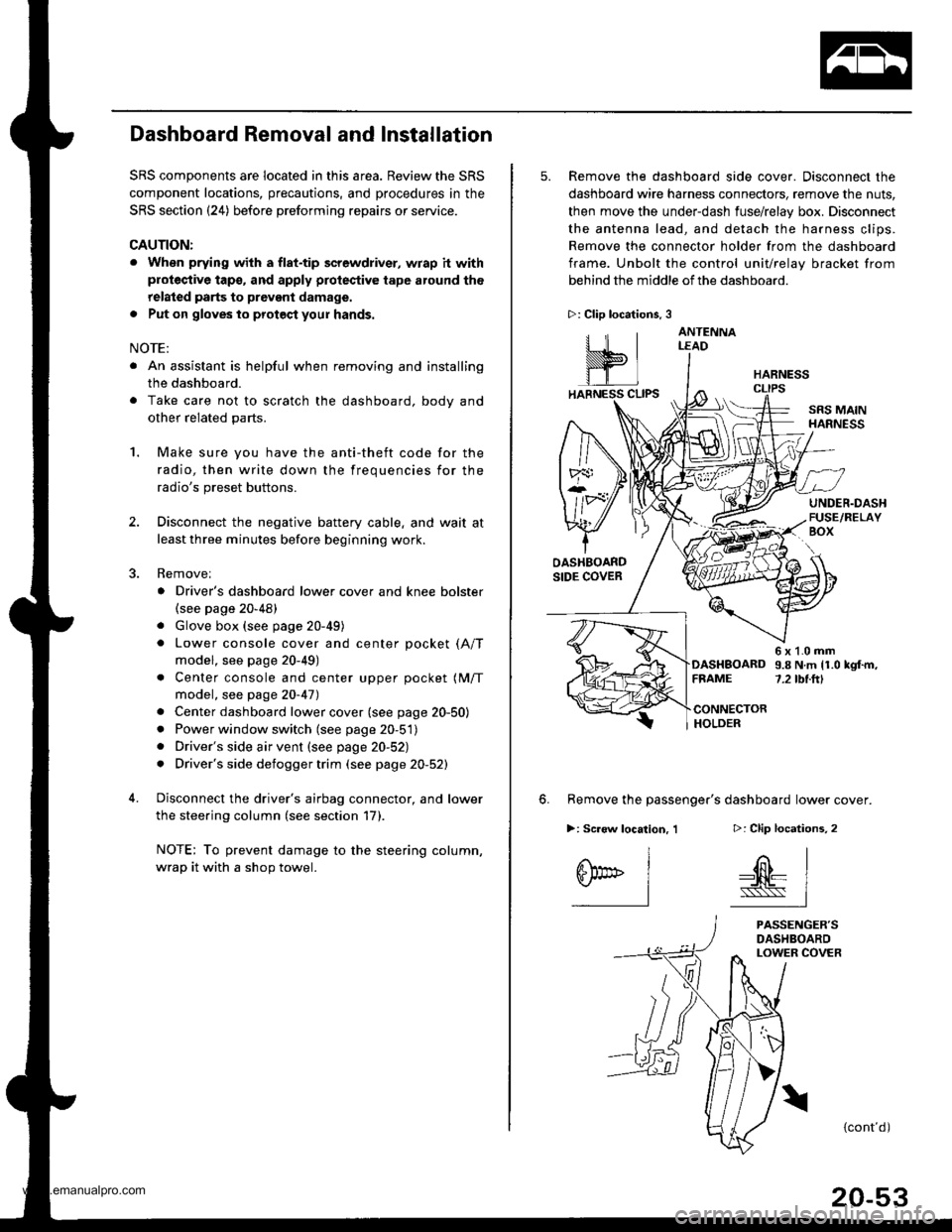
5. Remove the dashboard side cover. Disconnect the
dashboard wire harness connectors, remove the nuts,
then move the under-dash fuse/relay box. Disconnect
the antenna lead, and detach the harness clips.
Remove the connector holder from the dashboard
frame. Unbolt the control unit/relay bracket from
behind the middle of the dashboard.
HARNESS
6. Remove the passenger's dashboard lower cover.
D: Clip locations,
nl
-$t- Issj
I
ANTENNALEAD
>: Clip locations.
rttl
slllll
>: Scr€w location, 1
I
SF:oo I-l
SRS MAINHARNESS
UNDER.DASHFUSE/RELAYBOX
OASHBOARDSIDE COVER
6x1.0mm9.8Nm11.0kgf.m,7.2tbt.ftlDASHBOARDFFAME
CONNECTORHOLDER
PASSENGER'SDASHBOARDLOWER COVER
{cont'd)
www.emanualpro.com