1997 HONDA CR-V lights
[x] Cancel search: lightsPage 372 of 1395

ldle Control System
ldle Speed Setting (cont'd)
38 - 0O mod6l3:
NOTE: Before setting the idle speed, check the follow-
ing items:- The MIL has not been reported on.- lgnition timing- Spark plugs
- Air cleaner- PCV system
1. Start the engine. Hold the engine at 3.000 rpm with
no load (in Park or neutral) until the radiator fan
comes on, then let it idle.
Connect a tachometer.
Disconnect the IAC valve 2P connector and the EVAP
purge control solenoid valve 2P connector.
CONTROLSOLENOID VALVE
SOLENOID VALVE
lf the engine stalls, restart the engine with the accel-
erato. pedal slightly depressed. Stabilize the rpm at
1,000, then slowly release the pedal until the engine
idles.
Che€k the idle in no-load conditions: headlights, blow-
er fan, rear defogger, radiator fan, and air conditioner
are not operating,
ldle speed should bo:
480 t 50 rpm {in PErk or noutrall
11-170
lf necessary, adjust the idle speed, by turning the
idle adjusting screw.
After adjusting the idle speed, recheck the ignition
timing (see section 4). lf it is out of spec, go back to
steo 4.tDt.E
6. Turn the ignition switch OFF.
7. Reconnect the 2P connectors to the IAC valve and
the EVAP purge control solenoid valve, then do the
ECM/PCM reset procedure.
8. Restart and idle the engine with no-load conditions
for one minute, then check the idle speed.
ldle speod should be:,98 model:
750 t 50 rpm tin Park or neutral)'9!l - 00 modsls:
730 i 50 lpm lin Psrk or neutral)
NOTE: lf the idle speed increases to 780 t 50 rpm(770 1 50 rpml*, this means the EVAP system is
purging the canister. To stop the purging temporari-
ly, raise the engine speed above 1,000 rpm with the
accelerator pedal, then slowly release the pedal.*: '99 - 00 models
9. Let the engine idle for one minute with the head-
lights (Low) ON, and check the idle speed.
ldle speed should be:
38 mod6l:
750 f 50 rpm (in Palk or neutrall'99 - 00 modols:
730 t 50 rpm (in Palk or neutral)
10. Turn the headlights off. Let the engine idle for one
minute with the heater fan switch at Hl and air con-
ditioner on, then check the idle speed.
ldls spqed should be:'98 model:
780 t 50 rpm (in Park or neutrall'99 - 00 mod€ls:
7701 50 rpm lin Park or neutral)
lf the idle speed is not within specification. see the
Symptom Chart on page 11-64.
ADJUSTING
www.emanualpro.com
Page 401 of 1395

Emission Control System
System Description
The emission control system includes, a Three Way
Catalytic Converter {TWC), Positive Crankcase Ventilation
(PCV) svstem and Evaporative Emission (€VAP) Control
system. The emission control system is designed to meet
federal and state emission standards.
Tailpipe Emission
Inspsction
!@ Do not smoke during this procsdura. Keep
any open tlame away from your work area.
1. Start the engine. Hold the engine at 3,000 rpm with
no load (in Park or neutral) until the radiator fan
comes on, then let it idle,
Connect a tachometer.
Check and, if necessary, adjust the idle speed, (see
page 11-169, 170).
Warm up and calibrate the CO meter according to the
meter manufacturer's instructions.
Check idle CO with the headlights, heater blower, rear
window defogger, cooling fan, and air conditioner off.
(Canada) Pull the parking brake lever up. Start the
engine, then check that the headlights are off.
CO meter should indicate 0.1% maximum.
4.
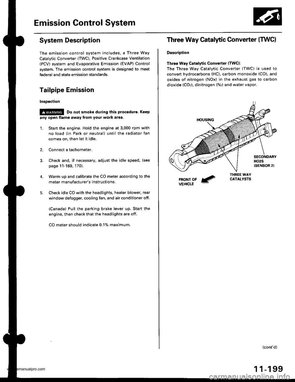
Three Way Catalytic Converter (TWCI
DsscriDtion
Three Way Catalytic Convertsr lTwcl:
The Three wav Catalvtic Converter (TWC) is used to
convert hydrocarbons (HC), carbon monoxide (CO), and
oxides of nitrogen (NOx) in the exhaust gas to carbon
dioxide (COr), dinitrogen (Nr) and water vapor,
{cont'd)
1 1-199
www.emanualpro.com
Page 605 of 1395

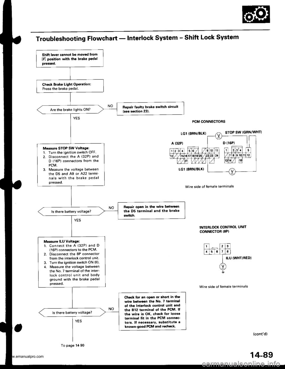
Troubleshooting Flowchart - Interlock System - Shift Lock System
PCM CONNECTORS
Wire side of lem6le termanals
INTERLOCK CONTROL UNIT
CONNECTOR I8P)
ILU IWHT/REDI
(cont'd)
Shift lever cannot be moved from
E] position with the brake P€delpreiseo.
Chock Brake Light Operation:Press the brake pedal.
Repsir fauhy brake switch circuit
{seo s€ction 231.Are the brake lights ON?
M€asure STOP SW voltage:l� Turn the ignition switch OFF.
2. Disconnect the A (32P) and
D (16P) connectors lrom thePCM.3. Measlre the voltage between
the D5 and Ag or A22 terma
nals with the brake Pedalpressed,
Repair opon in the wi.e be{w.enthe D5 terminal and the br.ke
switd!.
Measur€ ILU vohage:1. Connect the A {32P) and D
116P) connectors to the PCM.2. Disconnect the 8P connectorfrom the interlock control unit
3. Turn the ignition switch ON (ll).
4. Measure the voltage betweenthe No.7 terminalofthe inter
lock control unit and bodyground with the brake Pedalpressed,
Ch€ck for an opon or thon in the
wire Mwoon tho No. 7 terminrl
of the inte ock control unit and
the 812 termin.l of the PcM. ll
the wirs is OK, check tor loo3e
terminal fit in the PCM connec_
to13. ll nece3sary,3ubstitute a
known-good PCM and rechock.
ls there battery voltage?
To page 14 90
14-89
www.emanualpro.com
Page 642 of 1395

Electrical Troubleshooting ('98 - 00 Modelsl
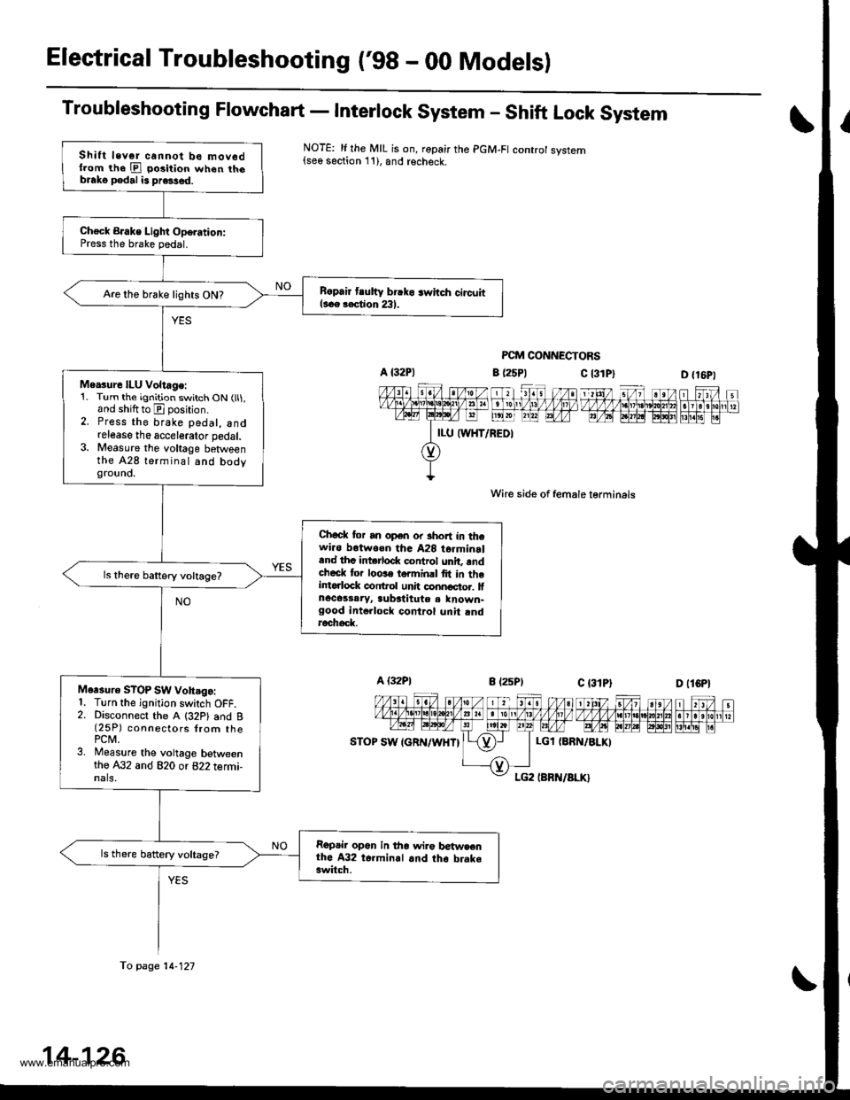
Troubleshooting Flowchart - Interlock System - Shift Lock System
NOTE: li the MIL is on, ropair the PGM-FI controt system{see section 11), and recheck.
PCM CONNECTORS
c l3lPl
Wire side of female lerminals
c t3lPt
D {16P1
1 tttt/ 5t/ 1 a t /tlt 1 t\/t ,/ VVV tl t ttj,r\1e\10l211n . I 3 rholr1 t?m@-@Effilil"
D (lCPl
| 2ttt/ ;t /n) ).tt)/ 1 21:/ tvvvvv nnvl.lnl2
I r r ero
12wE gp]P] polr EI!l!!i r.
a (25P1
LGl {8RN/ALKI
Shift levor cannot be mov6dllom the E po3ition when th6blako pedal is pre3sed.
Ch€ck BJake Light Oporation:Press the brake pedal.
B6pair tlutty brrko 3whch circuitl..e rection 231.Are the brake lights ON?
Me.sure ILU Voltage:1. Turn the ignition switch ON (ll1,and shiftto E position.2. Press the brake pedal, andrelease the accelerator pedal.3. Measure the voltage betweenthe A28 terminal and bodygrouno.
Chock tor an open or short in thewi.o botwoen tha A28 t6rminrland thc intorlod( control unit, rndcheck tor loose torminrl fit in theintorlock conftol unh connoctor. lfnocassaryr aubstitute a known-good intollock control unit rndroch6d(
Mor3uro STOP SW vohsgo:1. Turn the ignition switch OFF.2. Disconnect the A (32P1 and B(25P) connectors {rom thePCM.3. Measure the voltage betweenthe A32 and 820 or 822 termi-nals,
Repair op6n in tho wir€ betwsenthe A32 t6.minal and th6 brake3witch.
ls there battery voltage?
fo page 14-121
14-126
www.emanualpro.com
Page 657 of 1395
![HONDA CR-V 1997 RD1-RD3 / 1.G Workshop Manual
8. Set the control shaft to E] position. then install the
A,/T gear position switch on it.
CONTROL SHAFT
Install the AyT gear position switch cover and har-
ness clamp on the end cover.
Connect the HONDA CR-V 1997 RD1-RD3 / 1.G Workshop Manual
8. Set the control shaft to E] position. then install the
A,/T gear position switch on it.
CONTROL SHAFT
Install the AyT gear position switch cover and har-
ness clamp on the end cover.
Connect the](/manual-img/13/5778/w960_5778-656.png)
8. Set the control shaft to E] position. then install the
A,/T gear position switch on it.
CONTROL SHAFT
Install the Ay'T gear position switch cover and har-
ness clamp on the end cover.
Connect the A,/T gear position switch connector.
then install it on the connector bracket.
Turn the ignition switch ON (ll). Move the shift lever
through all gears, and check the AfI gesr position
switch synchronization with the A/T gear position
indicator.
9.
10.
11.
A/TGEARPOSMON A/T GEAR POSITIONINDICATOR INDICATOR'99 - 00 MODELS '�97 - 98 MOOELS
12, Start the engine. Move the shift lever through all
gears. and verify the following:
. The shift lever cannot be moved to E] position
from E position unless the shift lever is pulled.
. The engine will not start in any position other
than E or E.. The back-up lights come on when the shift lever
is in El position.
14-141
www.emanualpro.com
Page 658 of 1395

A/T Gear Position Indicator
1.
f nput Test -'97 - 98 Models
Remove the gauge assembly from the dashboard (see section 20). and disconnect the 14P connector from the gauge
assemblv (see section 23),
Inspect the connector and socket terminals to be sure they are all making good contact.
. lf the terminals are bent, loose, or corroded, repairthem as necessary, and recheck the system.. lf the terminals look OK, make the following input tests at the 14P connector.- lf I test indicates a problem, find and correct the cause, then recheck the system.- lf all the input tests prove OK, but the indicator is faulty. replace the printed circuit board,
GAUGE ASSEMBLY 14P CONNECTOR
Wire side of female terminals
CavityWirs
ColorTest ConditionTest: Desir€d ResultPossible Cause
{lf rosult is not obtainod)
YEL
lgnition switch ON (ll)Check for voltage to ground:
There should be battery voltage,
. Blown No. 25 (7.5 A) fuse in the
under-dash fuse/relay box. An open in the wire
RE D/BLKCombination light
switch ON and dash
lights brightness con-
trol dial on full bright
Check for voltage between No. 2
and No. 3 terminals;
There should be battery voltage.
Blown No. 47 (7.5 A) fuse in the
under-dash fuse/relay box
Faulty combination Iight switch
Faulty dash iight brightness
controller
An open in the wire
RED
4BLUShift lever in ECheck for continuity to ground:
There should be continuity.
NOTE: There should be no continu-
ity in any other shift lever position.
' Faulty Ay'T gear position switch. An open in the wireBRNShift lever in E
7YELShift lever in @
8BLKUnder all conditionsCheck for continuity to ground:
There should be continuity
. Poor ground {G401). An open in the wire
9GRN/BLK
lgnition switch ON {ll)
and shift lever in any
position except E
Check for voltage to ground:
There should be battery voltage
for two seconds after the ignition
switch is turned ON {ll), and less
than 1 V two seconds later,
' Faulty PCM. An open in the wire
10GRNShift lever in ECheck for continuity to ground:
There should be continuity.
NOTE: There should be no conti-
nuity in any other shift lever posi-
UOn.
. Faulty A,ff gear position switch. An open in the wire1'lREDShift lever in @
12WHTShift lever in E
BLVBLU
Shift lever in ENOTE: Do not push
the brake pedal.
14LT GRN
lgnition switch ON { ll)
and shift lever in any
position except E and
E
Check for voltage to ground:
There should be about 5 V.
. Faulty PCM. An open in the wire
14-142
www.emanualpro.com
Page 659 of 1395

L
Input Test -'99 - 00 Models
Remove the gauge assembly from the dashboard {see section 20), and disconnect the 14P connector from the gauge
assembly (see section 23).
Inspect the connector and socket terminals to be sure they are all making good contact.
a lf the terminals are bent. loose, or corroded. repair them as necessary. and recheck the system.
. lf the terminals look OK, make the following input tests at the 14P connector.- lf a test indicates a problem, find and correct the cause, then recheck the system.- lf all the input tests prove OK, but the indicator is faulty, replace the printed circuit board.
GAUGE ASSEMBLY 14P CONNECTOR
Wire side of female terminals
CavityWire
ColorTest ConditionTest: Desired ResuhPossible Caus6
{lf resutt is not obtainod)
1YEL
lgnition switch ON (ll)Check for voltage to ground:
There should be battery voltage.
. Blown No.25 (7.5 A) fuse in the
under-dash fuse/relay box. An open in the wire
2RE D/BLK
Combination light
switch ON and dash
lights brightness con-
trol dial on full bright
Check for voltage between No. 2
and No.3 terminals:
There should be battery voltage.
Blown No. 47 {7.5 A) fuse in the
under-dash fuse/relay box
Faulty combination light switch
Faulty dash light brightness
controller
An open in the wire
5RED
BRNShift lever in ECheck for continuity to ground:
There should be continuity.
NOTE: There should be no continu-
ity in any other shift lever position.
. Faulty A/T gear position switch. An open in the wire7YELShift lever in E
'10BLUShift lever in E
LT BLU
lgnition switch ON (ll),
shift lever in E. and
Over-Drive is OFF bypressing O/D switch.
Check for continuity to ground:
There should be continuity.
Faulty O/D switch
Faulty A/T gear position switch
Faulty PCM
An open in the wire
8BLKUnder all conditionsCheck for continuity to ground:
There should be continuity
. Poor ground (G401)
. An open in the wire
9a:FI\|/Et| ta
lgnition switch ON (ll)
and shift lever in any
position except E
Check for voltage to groundl
There should be battery voltage
for two seconds after the ignition
switch is turned ON (ll). and less
than 1 V two seconds later.
. Faulty PCM. An open in the wire
11REDShift lever in SCheck for continuity to ground:
There should be continuity.
NOTE: There should be no conti-
nuity in any other shift lever posi-
Iton.
. Faulty A/T gear position switch. An open in the wire12WHTShift lever in E
BLI(BLU
Shift lever in ENOTE: Do not push
the brake pedal.
14LT GRN
lgnition switch ON (ll)
and shift lever in any
position except E and
E
Check for voltage to groundl
There should be about 5 V,
. Faulty PCM. An open in the wire
14-143
www.emanualpro.com
Page 929 of 1395

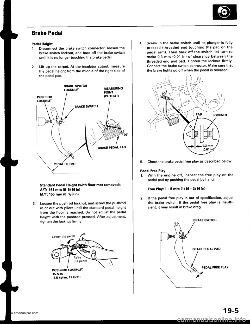
Brake Pedal
Pedal Hoight
1. Disconnect the brake switch connector, loosen the
brake switch locknut, and back off the brake switch
until it is no longer touching the brake pedal.
2. Lift up the carpet, At the insulator cutout, measure
the pedal height from the middle of the right side of
the oedal pad.
BRAKE SWITCH
ERAKE SWITCH
Standard Pedal Height (with floor m8i removed):
A/T: 161 mm (5 5/16 in)
M/T: 155 mm {6 U8 in}
Loosen the pushrod locknut, and screw the pushrod
in or out with pliers until the standard pedal height
from the floor is reached. Do not adjust the pedal
height with the pushrod pressed. After adiustment,
tighten the locknut firmly.
PUSHROD LOCKNUT
15 N.m11.5 kgj m, 11 lbf ftl
4. Screw in the brake switch until its plunger is fully
pressed (threaded end touching the pad on the
pedal arm), Then back otf the switch 1/4 turn to
make 0.3 mm (0.01 in) of clearance between the
threaded end and pad. Tighten the locknut firmly.
Connect the brake switch connecto.. Make sure that
the brake lights 90 off when the pedal is released
5. Checkthe brake pedalfree play as described below
Pedal Free Play
1. With the engine off. inspect the free play on the
pedal pad by pushing the pedal by hand-
Free Play: 1 - 5 mm (1/16 - 3/16 in)
2. lf the pedal free play is out of specification, adiust
the brake switch. lf the pedal free play is insuffi-
cient, it may result in brake drag.
swtTcH
PEOAL PAD
PEDAL FREE PLAY
19-5
www.emanualpro.com