Page 1015 of 1395
Glass
Windshield Replacement (cont'dl
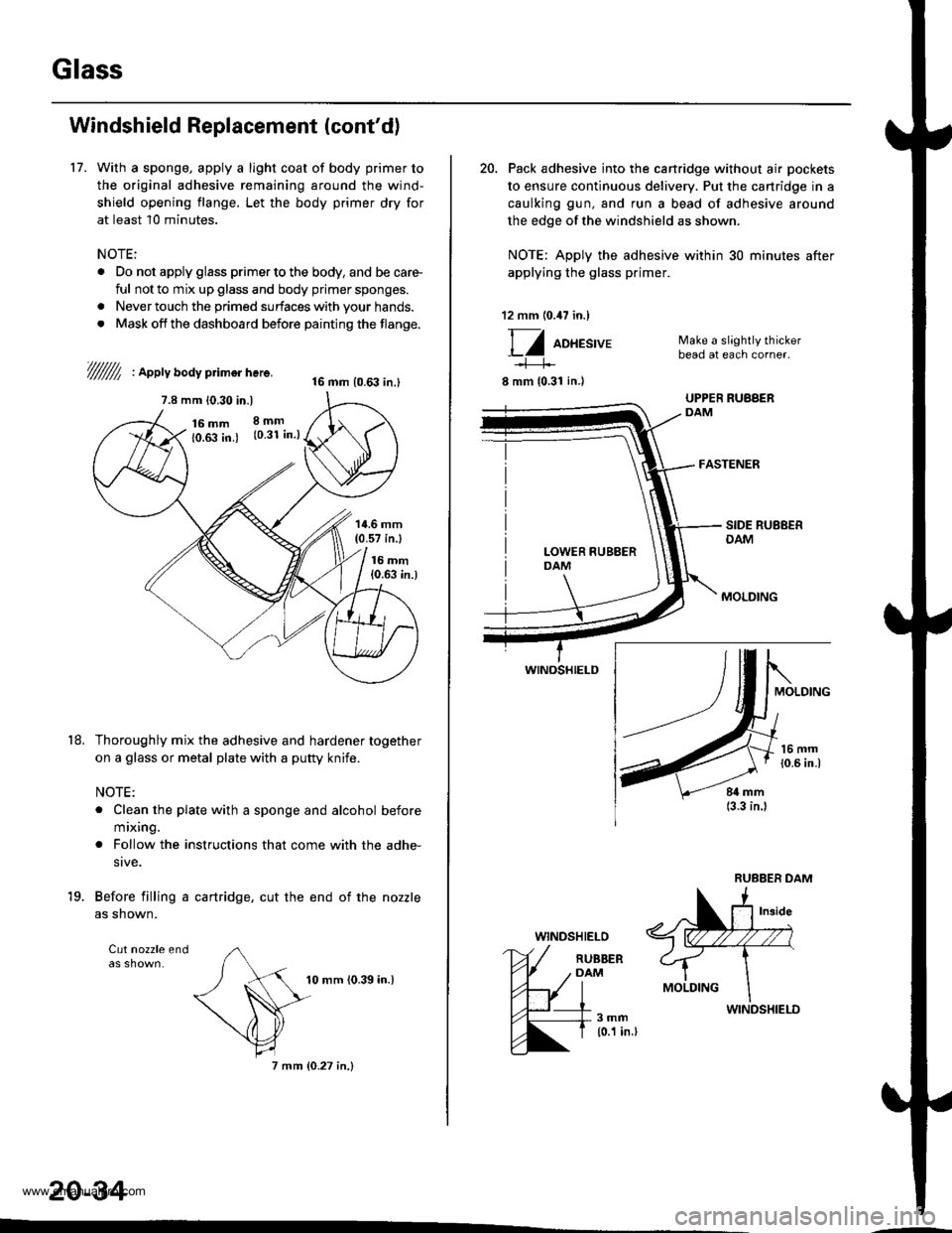
17. With a sponge, apply a light coat of body primer to
the original adhesive remaining around the wind-
shield opening flange, Let the body primer dry for
at least 10 minutes.
NOTE:
. Do not apply glass primer to the body, and be care-
ful not to mix up glass and body prjmer sponges.
. Never touch the primed surfaces with your hands.
. Mask off the dashboard before painting the flange.
///////l , apptv aoav primor here.16 mm {0.63 in.l
7.8 mm 10.30 in.)
16 mm10.fi in.)
8mm(0.31 in.)
't8,
14.6 mm(0.57 in.l
16 mm{0.63 in.)
Thoroughly mix the adhesive and hardener together
on a glass or metal plate with a putty knife.
NOTE:
. Clean the plate with a sponge and alcohol before
mixing.
. Follow the instructions that come with the adhe-
sive.
Before filling a cartridge, cut the end of the nozzle
as shown.
Cut nozzle end
'19.
10 mm {0.39 in.)
7 mm {0.27 in,}
20-34
20, Pack adhesive into the cartridge without air pockets
to ensure continuous delivery. Put the cartridge in a
caulking gun, and run a bead of adhesive around
the edge of the windshield as shown.
NOTE: Apply the adhesive within 30 minutes after
applying the glass primer.
12 mm (0.47 in.)
Ff oo*tt'u'
8 mm {0.31 in.l
WINOSHIELD
WINDSHIELO
Make a slightly thickerbead at each corner.
FASTENER
RUBBERDAM
3mm{0.1 in.l
www.emanualpro.com
Page 1025 of 1395
lnterior Trim
Headliner Removal and Installation
CAUTION: When prying with a tlat-tip screwdriver,
wrap it with protective tape to prevent damage.
NOTE:
. Take care not to bend and scratch the headliner.o Be careful not to damage the dashboard and other
interior trim.
1. Remove:
. Front and rear door side trim (see page 20-41). Front pillartrim (see page 20-41)
. Center pillar lower trim panel (see page 20-41). Center pillar upper trim (see page 20 41). Rear seat (one side, see page 20-63). Cargo area floor and cargo storage bin
{see page 20-43)
. Rear trim panel (see page 20-421
. Rear side trim panel (oneside, see page 20-42l,
. Rear hatch glass support strut (one side, seepage 20-78)
. Ouaner pillar trim panel {one side, see page 20-
42)
. Ceiling light, interior light and trunk light(see section 23)
. Rearview mirror (see page 20-28)
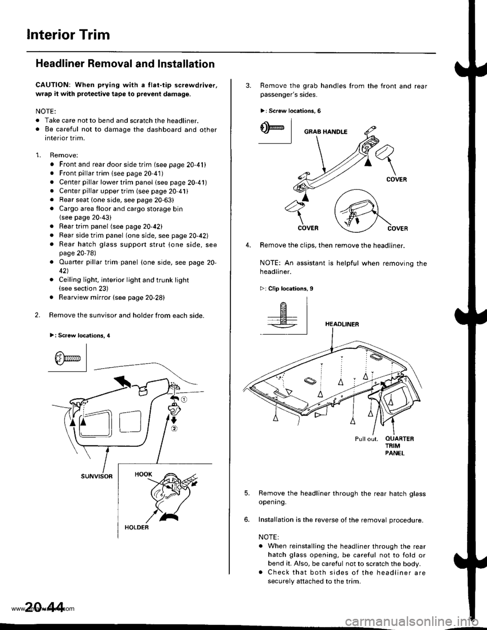
2. Remove the sunvisor and holder from each side.
>: Scaew location3, 4
I
A\"r- |Yr* || -
suNvtsoR
20-44
3. Remove the grab handles from
passenger's sides.
>r Screw locations, 6
the front and rear
ry_l
COVER
4. Remove the clips, then remove the headliner.
NOTE: An assistant is helpful when removing the
headliner.
>: Clip locations,9
HEADLINER
Pullout. OUARTERTRIMPANEL
5. Remove the headliner through the rear hatch glass
openrng.
6. Installation is the reverse of the removal procedure.
NOTE:
. When reinstalling the headliner through the rear
hatch glass opening, be careful not to fold or
bend it, Also, be careful not to scratch the body.. Check that both sides of the headliner are
securely attached to the trim.
www.emanualpro.com
Page 1028 of 1395
Dashboard
Genter Console Replacement
M/T model:
NOTE; Take care not to scratch the dashboard and related
parts,
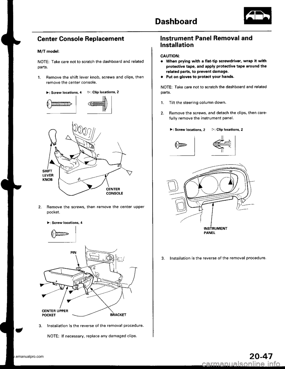
1, Remove the shift lever knob. screws and clips. then
remove the center console.
>: Screw location3,
I
6-Emmmn> |
4 >: Clip locations.2
#\*K/
I
Remove the screws, then
pocket.
remove the center upper
>: Screw locations, 4
3. Installation is the reverse of the removal procedure.
NOTE: lf necessary, replace any damaged clips.
lnstrument Panel Removal and
Installation
CAUTION:
. When prying with a flat-tip screwdriver. wrap it with
protestive tape, and apply prolestive tape around the
related parts, to provont damago,
a Put on glovss to protect your hands.
NOTE: Take care not to scratch the dashboard and related
pans.
1. Tilt the steering column down.
2. Remove the screws, and detach the clips, then care-
fullv remove the instrument oanel.
3. Installation is the reverse of the removal procedure.
>: Clip locations,2
r#sr |
=-l,]
>: Screw locations,2
^l
arl
l
PANEL
20-47
www.emanualpro.com
Page 1029 of 1395
Dashboard
SRS components are located in this area. Review the SRS
component locations, precautions, and procedures in the
SRS section (24) before performing repairs or service.
GAUTION:
. When prying with a tlat-tip screwdriver, wrap h withproteqtive tape, and apply protective tape around the
relat€d parts, to prevent damage,
. Put on glovgs to protect your hands.
NOTE: Take care not to scratch the dashboard and relatedpans.
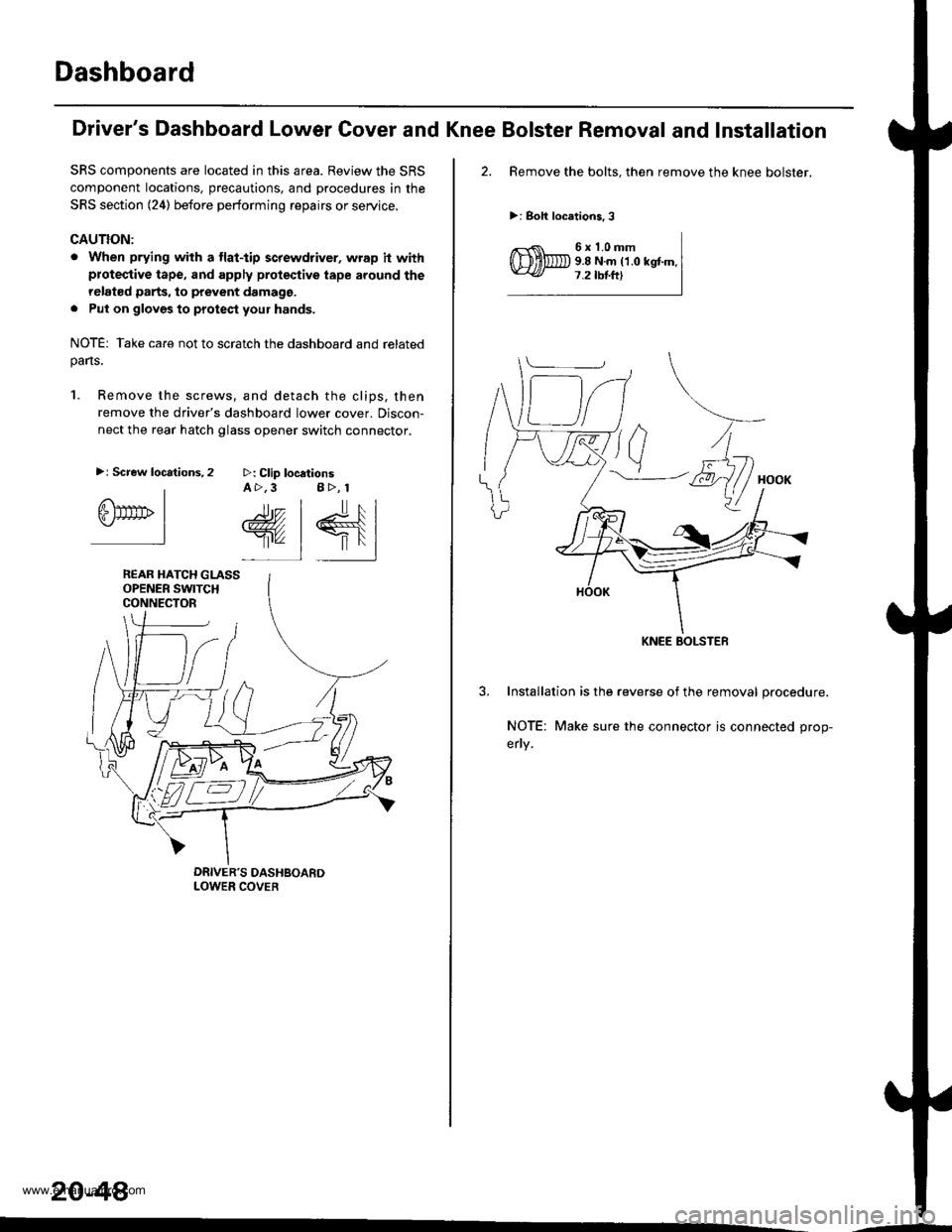
1. Remove the screws, and detach the clips, then
remove the driver's dashboard lower cover. Discon-
nect the rear hatch glass opener switch connector.
>: Clip locationsA >,3 B>, 1
rr.- | lr, l
@, | €{lr'" 1 |'l
>: Screw locations,2
IGlTtrrrb I.-l
REAR HATCH GLASSOPENER SWITCHCONNECTOR
20-48
'-
Driver's Dashboard Lower Cover and Knee Bolster Removal and Installation
2. Remove the bolts. then remove the knee bolster.
>: Boh locations,3
6x1.0mm9.8 N.m ('1.0 kgtm.7.2 tbtftl
3. Installation is the reverse of the removal procedure.
NOTE: Make sure the connector is connected prop-
erly.
KNEE BOLSTEF
www.emanualpro.com
Page 1030 of 1395
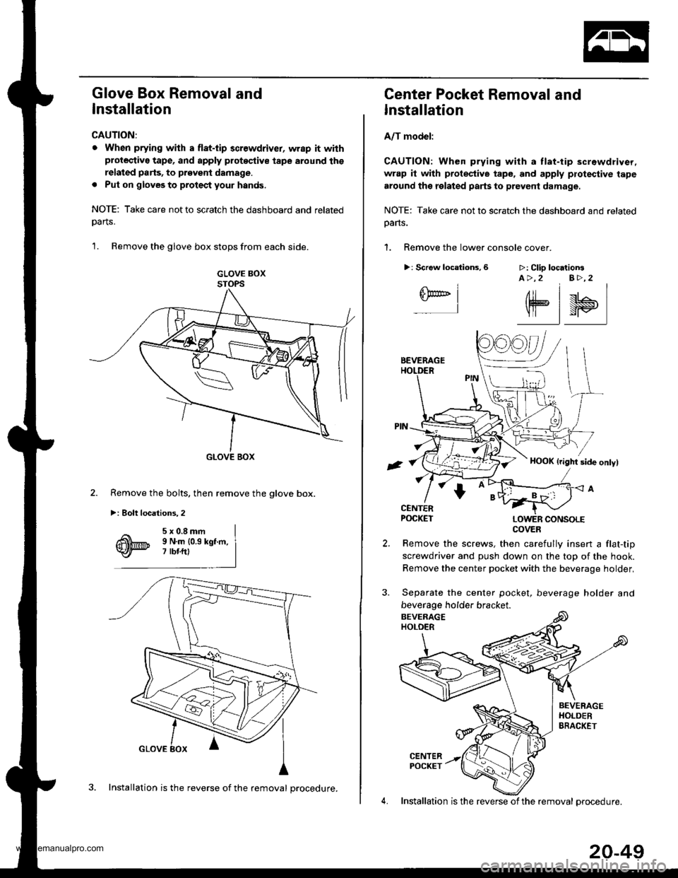
Glove Box Removal and
Installation
CAUTION:
. When prying with a flat-tip 3crewdriver, wrap it withprotective tape, and apply protoqtive tape around ths
related parts, to prgveni damage.
. Put on gloveg to protect your hands.
NOTE: Take care not to scratch the dashboard and related
oarts.
1. Remove the glove box stops from each side.
GLOVE BOXSTOPS
GLOVE BOX
Remove the bolts, then remove the glove box.
>i Bolt locations,2
3. Installation is the reverse of the removal procedure.
20-49
Center Pocket Removal and
Installation
A/T model:
CAUTION: When prying with a tlat-tip screwdriver,
wrap it with protestive tape, and apply protective tape
around the related parts to prevent damage.
NOTE: Take care not to scratch the dashboard and related
oans.
1. Remove the lower console cover.
>: Scrgw locations,6 >: Clip locationsA >,2 B>,2
6F@'' I-l
elsl
Remove the screws, then carefully insert a flat-tip
screwdriver and push down on the top of the hook.
Remove the center pocket with the beverage holder,
Separate the center pocket, beverage holder and
beverage holder bracket.
4. Installation is the reverse of the removal orocedure.
COVER
www.emanualpro.com
Page 1031 of 1395
Dashboard
Center Dashboard Lower Gover
Removal and Installation
SRS components are located in this area. Review the SRS
component locations, precautions, and procedures in the
SRS section {24) before performing repairs or service
CAUTION:
. Wh€n prying with a flat-tip screwdrivet, wrap it with
protective tap€, and apply proteclive tape around the
rslated parts to prevenl damage.
. Put on glovgs to protect your hands.
NOTE: Take care not to scratch the dashboard and related
oarts.
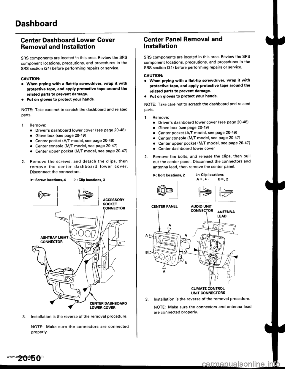
1. Remove:
. Driver's dashboard lower cover (see page 20-48)
. Glove box (see page 20-49)
. Center pocket (AVT model. see page 20-49)
. Center console (M/f model, see page 20-41l,
. Center upper pocket (M/T model, see page 2O-47J
2. Remove the screws, and detach the clips. then
remove the center dashboard lower cover.
Disconnect the connectors.
>: Screw locationa,.a
I
6br" I-l
3. Installation is the reverse of the removal procedure-
NOTE: Make sure the connectors are connected
properly.
20-50
>: Clip loc.tion6,3
I5
\"P I AccEssoRyI socKET
Center Panel Removal and
lnstallation
SRS components are located in this area. Review the SRS
comDonent locations, precautions, and procedures in the
SRS section (24) before performing repairs or servace.
CAUTION:
. When prying with a flat-tip screwdriver, wrap it with
protective tape, and apply protective tape around the
relatgd parts to prevent damage.
. Put on gloves to protect your hands.
NOTE: Take care not to scratch the dashboard and related
parts.
1. Remove:
. Driver's dashboard lower cover (see page 20-48)
. Glove box (see page 20-49)
. Center pocket (A,/T model, see page 20-49)
. Center console (M/T model, see page 20-47)
. Center upper pocket {M/T model, see page 20-47)
. Center dashboard lower cover
2. Remove the bolts, and release the clips. then pull
out the center panel. Disconnect the connectors and
antenna lead. then remove the center panel.
CLIMATE CONTBOLUNIT CONNECTORS
3. Installation is the reverse of the removal procedure.
NOTE: Make sure the connectors and antenna lead
are connected proPerly.
>: Clip location3A >,4 B>,2
tt.t !^ t u . I\lJS>,, \>ryI is I r-,/'
AUOIO UNIT
>: Bolt locations,2
(8NED L-l
CENTER PANEL
www.emanualpro.com
Page 1032 of 1395
Power Window Switch Removal
and Installation
CAUTION:
. When prying with a flat.tip screwdriver, wrap it withprotective tape, and apply protective tape around th€
related parts to ptavgnt damage.
. Put on gloves to protect your hands.
NOTE: Take care not to scratch the dashboard and relatedparts.
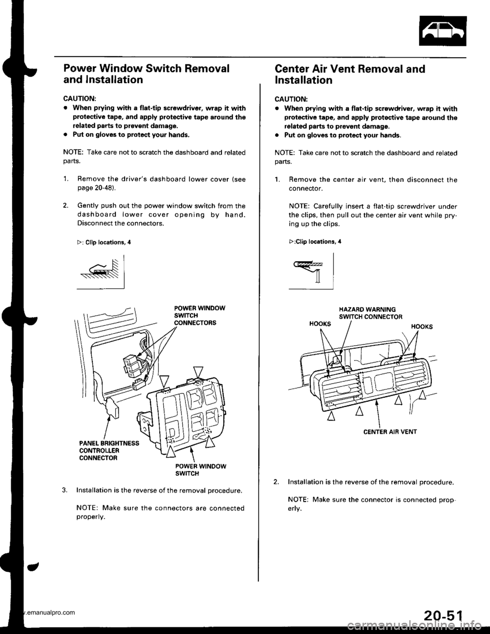
'L Remove the driver's dashboard lower cover (see
page 20-48).
2. Gently push out the power window switch from the
dashboard lower cover opening by hand.
Disconnect the connectors.
>: Clip locations, 4
POWER WTNOOWSWITCH
Installation is the reverse of the removal procedure,
NOTE: Make sure the connectors are connectedproperly.
Center Air Vent Removal and
Installation
CAUTION:
. When prying with a flat.tip screwdriver, wrap h withprotective tape, and apply proteqtive tape around the
rolated parts to prevont damage.
. Put on gloves to protect your hands.
NOTE: Take care not to scratch the dashboard and related
pans.
1. Remove the center air vent. then disconnect the
connector.
NOTE: Carefullv insen a flat-tio screwdriver under
the clips, then pull out the center air vent while pry-
ing up the clips.
Installation is the reverse of the removal procedure.
NOTE; Make sure the connector is connected prop-
>:Clip locations.,l
I
ffil
CENTER AIB VENT
20-51
www.emanualpro.com
Page 1033 of 1395
Dashboard
Side Air Vent Removal and
lnstallation
CAUTION:
. When prying with a flat-tip screwdriver, wrap it with
protec'tive tape, and apply protcctive tape around the
related parts to provent damage.
. Put on glov€s to protect your hands.
NOTE: Take care not to scratch the dashboard and related
parts.
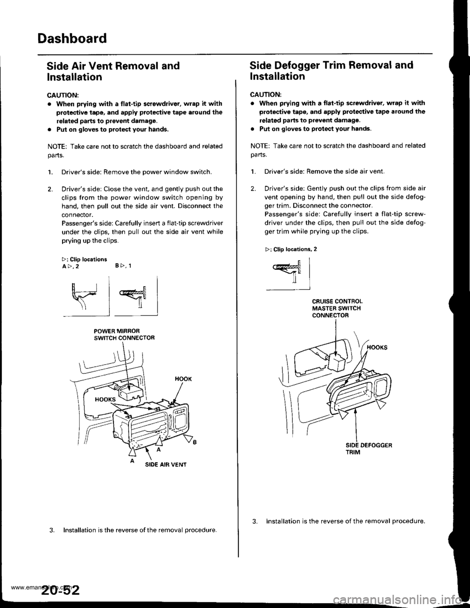
1. Driver's side: Remove the Dower window switch.
2. Driver's side: Close the vent, and gently push out the
clips from the power window switch opening by
hand, then pull out the side air vent. Disconnect the
connector.
Passenger's side: Carefully insert a flat-tip screwdriver
under the clips. then pull out the side air vent while
prying up the clips.
>: Clip locationsA>,2 B>, 1
sl 4
POWER MIRRORSWITCH CONNECTOR
SIDE AIB VENT
3. Installation is the reverse ofthe removal procedure.
20-52
3. Installation is the reverse of the removal procedure.
Side Defogger Trim Removal and
lnstallation
CAUTION:
. when prying whh a flat-tip sctewdriver, wrap it with
protective tape, and apply protectiv€ tape around the
relatgd parts to prevent damagg.
. Put on gloves to protect your hands.
NOTE: Take care not to scratch the dashboard and related
oa rts.
1. Driver's side: Remove the side air vent.
2. Driver's side: Gently push out the clips from side air
vent opening by hand, then pull out the side defog-
ger trim. Disconnect the connector.
Passenger's side: Carefully insert a flat-tip screw-
driver under the clips, then pull out the side defog-
ger trim while prying up the clips.
>: Clip locations, 2
c1
ffil-t
TRIM
www.emanualpro.com