Page 350 of 1395
PGM-FI System
HO2S Replacement
1. Disconnect the HO2S 4P connector, and remove the
HO2S.
PRIMARY H02S:
PRIMARY HO2S4P CONNECTOR
02 SENSORWRENCH
PRIMARYHO2S44 N.m{4.5 kgt m,33lbf.ftl
SECONDARY HO2S:
SECONDARY HO2S4,0 N.m (4.5 kg{.ft, 33 lbtftl
2. Install the HO2S in reverse order of removal.
11-148
www.emanualpro.com
Page 383 of 1395
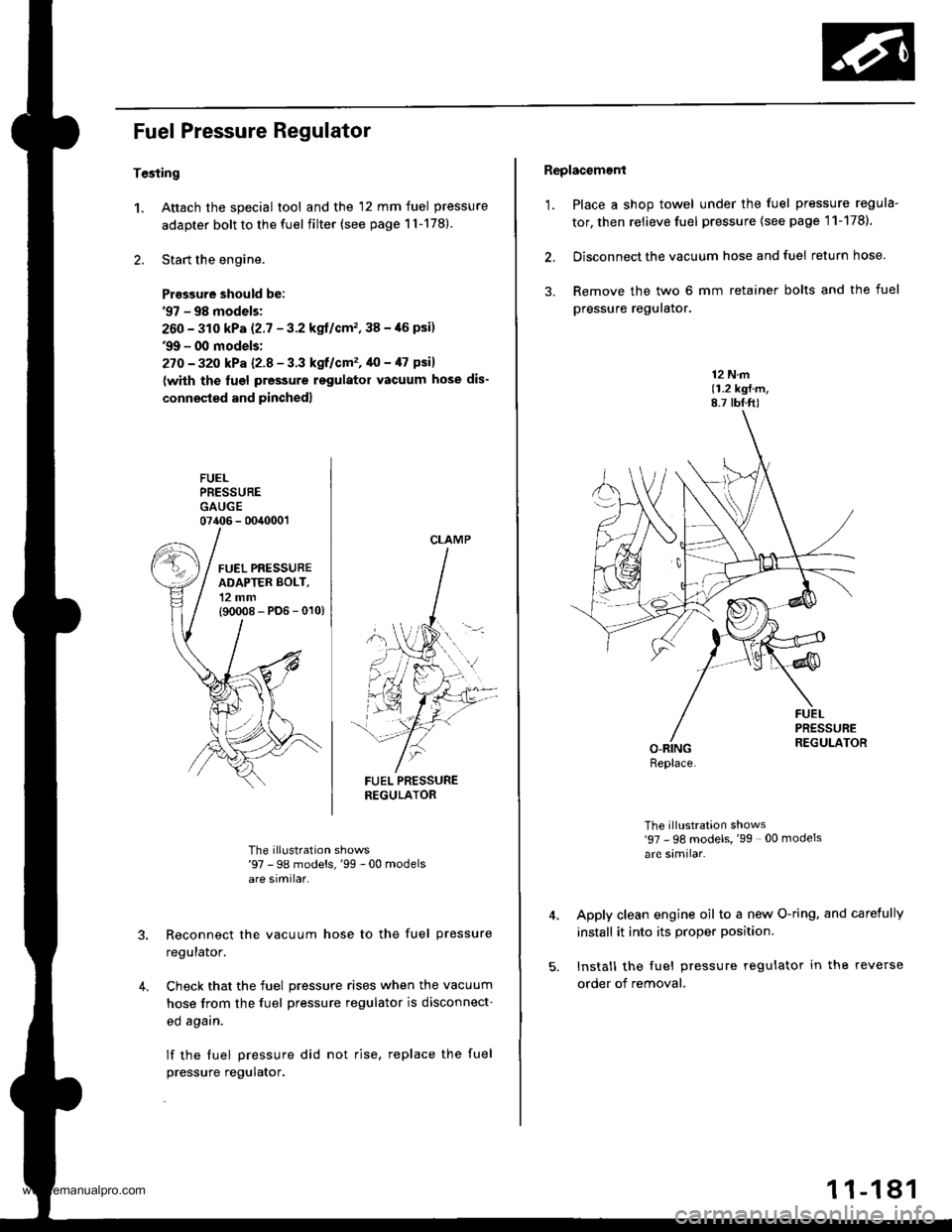
Fuel Pressure Regulator
Tesiing
1. Attach the special tool and the 12 mm fuel pressure
adapter bolt to the fuel filter (see page 1l-178)
2. Start the engine.
Prasgure should be:'97 - 98 models;
260 - 310 kPa (2.7 - 3.2 kgl/cm'�,38 -,16 psi)'9!t - 00 models:
27O - 32o kPa l2-8 - 3.3 kgf/cm'�, 40 - /l7 psil
(with the lugl pressure rsgulator vacuum hose dis-
connested and pinched)
FUELPRESSUREGAUGE07406 - 0040001
FUEL PRESSURENEGULATOR
The illustration shows'97 - 98 models,'99 -00 modelsare similar.
Reconnect the vacuum hose to the fuel pressure
regulalor.
Check that the fuel pressure rises when the vacuum
hose from the fuel pressure regulator is disconnect-
ed agarn.
lf the fuel pressure did not rise, replace the fuel
pressure regulator.
4.
CLAMP
Replacement
'1. Place a shop towel under the fuel pressure regula-
tor, then relieve fuel pressure (see page 11-1781.
2. Disconnect the vacuum hose and fuel return hose.
3. Remove the two 6 mm retainer bolts and the fuel
pressure reguralor.
12 N.m(1.2 kgf.m,8.7 tbf.ft)
The illustration shows'97 - 98 models, '99 00 models
are similar.
Apply clean engine oil to a new O-ring. and carefully
install it into its proper position.
Install the fuel pressure regulator in the reverse
order of removal,
Replace.
1 1-181
www.emanualpro.com
Page 384 of 1395
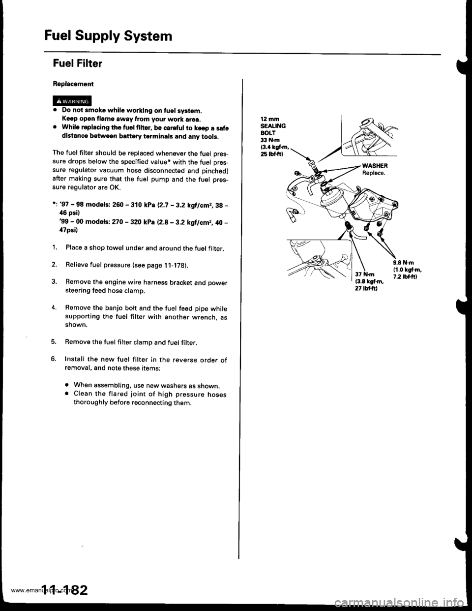
Fuel Supply System
Fuel Filter
Replacamont
. Do not smoke whilo working on tuol syslom,Keep open flame away from your work area.. While rsplscing ths fuolfihor. bo careful to ko€p a safedistanca betweon baftsry tarminals and any tools,
The fuel filter should be replaced whenever the fuel Dres-sure drops below the specified value* with the fuel pres-
sure regulator vacuum hose disconnected and pinchedl
after making sure that the fuel pump and the fuel pres-
sure regulator are OK.
i: '97 - 98 modelsi 260 - 310 kPa 12.7 - 3.2 kgllcm2,3g -
46 psil'99 - 00 mod6fs: 270 - 320 kP8 12.8 - 3.2 kgilcm2, 40 -
il7psi)
1, Place a shop towel under and around the fuel filter.
2. Relieve fuel pressure (see page l1-l7B).
3. Remove the engine wire harness bracket and power
steering feed hose clamp.
4. Remove the banjo bolt and the fuel feed pipe whilesupporting the fuel filter with another wrench. assnown.
Remove the fuelfilter clamp and fuel filter,
Install the new fuel filter in the reverse orde. ofremoval, and note these items:
. When assembling, use new washers as shown.. Clean the flared joint of high pressure nosesthoroughly before reconnecting them.
11-182
12 mmSEAUNGBOLT33 hl.m
l3.a kgt m,25 lbt frl
9.8 N.|n11.0 kgf'm,t.2 tbt.ftl
www.emanualpro.com
Page 385 of 1395
Fuel Pump
Testing
lf you suspect a problem with the fuel pump, check that
the fuel pump actually runs; when it is oN (ll), you will
hear some noise if you hold your ear to the fuel fill port
with the fuel fill cap removed. The fuel pump should run
for two seconds when ignition switch is first turned ON (ll).
lf the fuel pump does not make noise, check it as follows:
1. Fold the left rear seat cushion forward, and remove
the base frame cover (see section 20).
2, Remove the access panel from the floor.
3. Make sure the ignition switch is OFF, then discon-
nect the fuel pumP 5P connector.
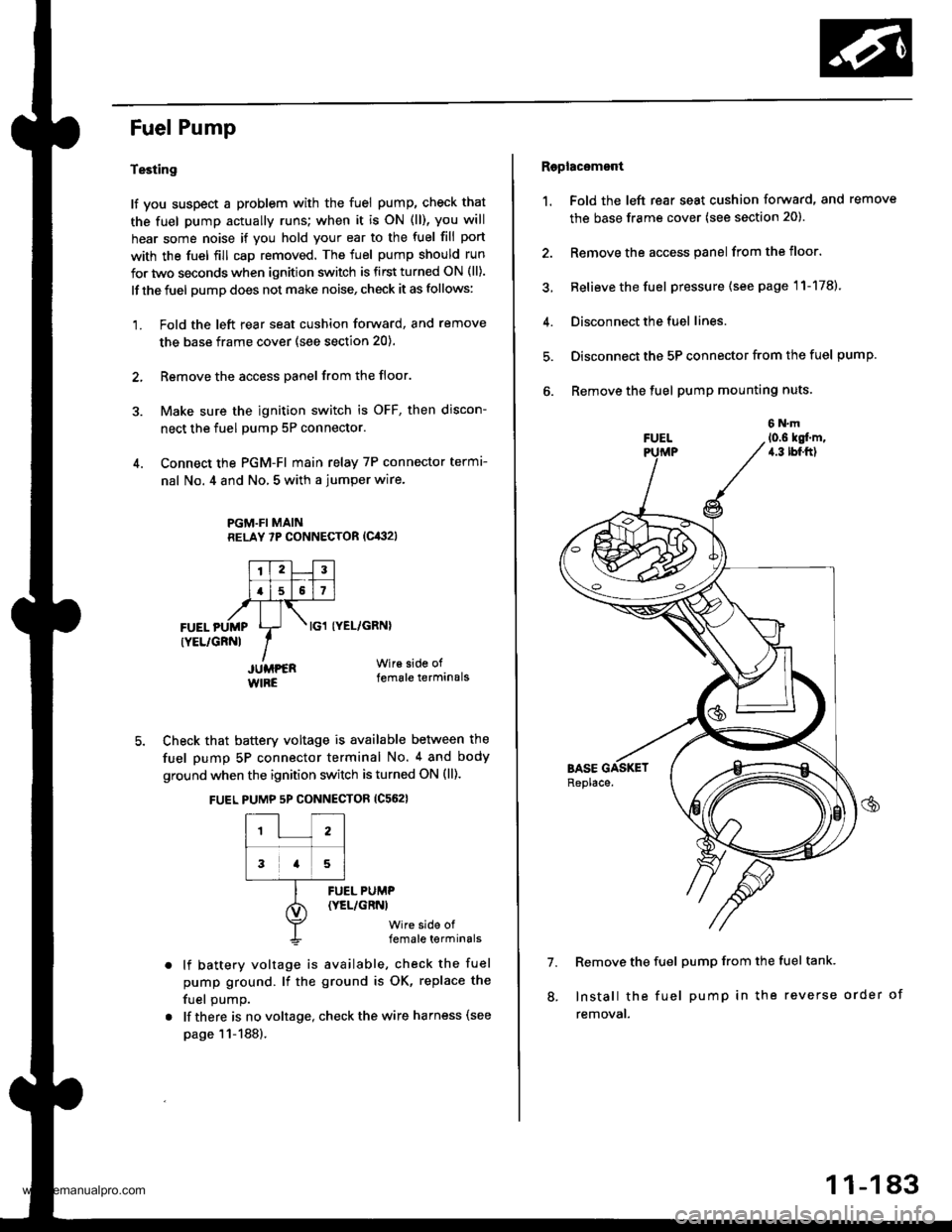
4. Connect the PGM-FI main relay 7P connector termr-
nal No. 4 and No, 5 with a jumper wire.
PGM.FI MAINRELAY 7P CONNECTOR (Cit:}2l
I'TtlJilt f -r'-r ll.l5l517l,frTt-,at\FUEL pUMp Lr- . tcl tyEL/cRNl
rYEL/cRNl IIJUMPER Wir€ side of
WIRE female terminals
5. Check that battery voltage is available between the
fuel pump 5P connector terminal No. 4 and body
ground when the ignition switch is turned ON (ll).
FUEL PUMP 5P CONNECTOR {C562}
12
3a5
lf battery voltage is available, check the fuel
pump ground. lf the ground is OK, replace the
fuel oumo.
lf there is no voltage, check the wire harness (see
page 11-188).
FUEL PUMP(YEL/GRNI
wire side offemale terminals
Raplac6mont
1. Fold the left rear seat cushion forward, and remove
the base frame cover (see section 20).
2. Remove the access panel from the floor.
3, Relieve the fuel pressure (see page 11-178).
4. Disconnect the fuel lines.
5. Disconnect the 5P connector from the fuel pump.
6. Remove the fuel pump mounting nuts.
7. Remove the fuel pump from the fuel tank.
Install the fuel pump in the reverse order of
removal.
8.
11-183
www.emanualpro.com
Page 393 of 1395
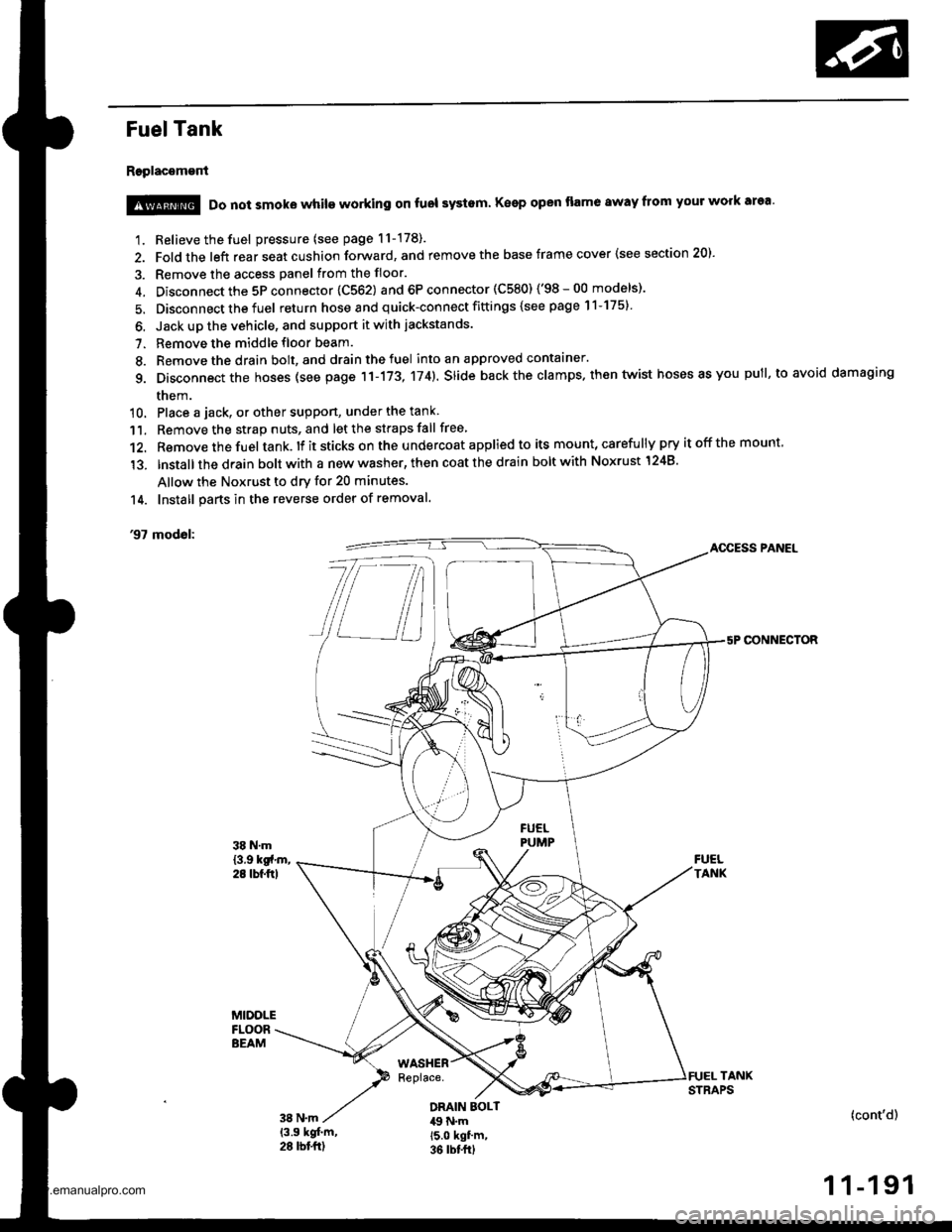
Fuel Tank
Replacement
1. Relieve the fuel pressure (see page 11-178).
2. Fold the left rear seat cushion forward, and remove the base frame cover {see section 20).
3. Remove the access panel from the floor.
4. Disconnect the 5P connector 1C562) and 6P connector (C580) ('98-00 models)'
5. Disconnect the fuel return hose and quick-connect fittings {see page 11-175}
6. Jack up the vehicle, and support it with jackstands.
7. Remove the middle floor beam.
8. Remove the drain bolt, and drain the fuel into an approved contaaner.
g. Disconnect the hoses (see page 11-173, 174). slide back the clamps. then twist hoses as you pull, to avoid damaging
them.
10. Place a jack, or other suppon, under the tank
11. Remove the strap nuts, and let the straps fall free
12. Remove the fuel tank. lf it sticks on the u ndercoat applied to its mount, carefu lly pry it off the mount,
'13. lnstallthe drain bolt with a new washer, then coat the drain bolt with Noxrust 1248'
Allow the Noxrust to dry for 20 minutes.
14. Install parts in the reverse order of removal.
'97 modol:AOCESS PANEL
CONNECTOR
@ Do not smoke while working on fuol systam Keep open flame away from your work area'
DRAIN EOLT49 N.m15.0 kgf'm,36 rbt frl
(cont'd)
1 1-191
www.emanualpro.com
Page 432 of 1395
Glutch Master Cylinder
Removal/lnstallation
CAUTION:
. Do not spill brake fluid on the vehicle; it may damage
the paint; if brake tluid does contact the paint. wash
it off immediately with water.
. Plug the end ol the clutch line and leservoir hose
with a shop towel to prevent brake tluid trom coming
out.
The brake fluid may be sucked out through the top
of the master cylinder reservoir with a syringe.
Disconnect the clutch line and reservoir hose from
the clutch master cylinder,
't.
9.8 N.m 11.0 kst m,7.2 tbf.ftl
CLUTCH LINE
19 N'm 11 9 kgJ m'
14 lbf.frl
Remove the reservoir from the engine compartment
bulkhead.
13 N.m t1.3 kgt.m,g.il lbtft)
4. Prv out the lock pin, and pull the pedal pin out of
the voke. Remove the nuts.
NUTSI x 1.25 mm
5, Remove the clutch master cylinder.
CLUTCH MASTERCYLINDEF
Install the clutch master cylinder in the reverse
order of removal.
NOTE: Bleed the clutch hydraulic system {see page
12-61.
12-5
www.emanualpro.com
Page 433 of 1395
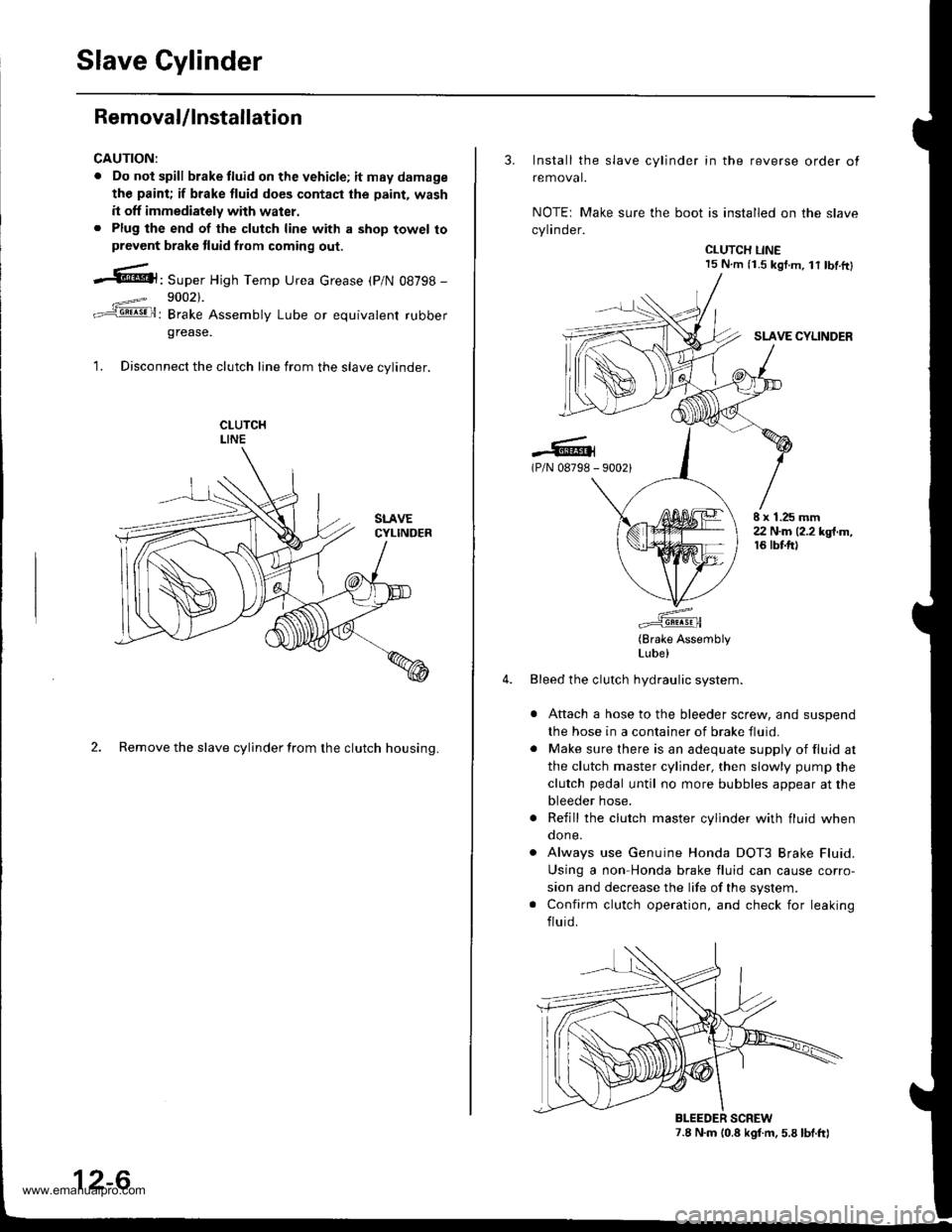
Slave Cylinder
RemovaUlnstallation
CAUTION:
. Do nol spill brake tluid on the vehicle; itmaydamage
the paint; if brake fluid do€s contast the paint, wash
it off immediately with water.. Plug the end of the clutch line with a shop towel toprevcnt brake tluid from coming out.
.6|l,Super High Temp Urea crease (p/N 08798 -
9002).
: Brake Assembly Lube or equivalent rubber
grease.
1. Disconnect the clutch line from the slave cvlinder.
2. Remove the slave cylinder from the clutch housing.
12-6
3. Install the slave cylinder in the reverse order ot
removal.
NOTEr Make sure the boot is installed on the slave
cylinder.
CLUTCH LINE15 N.m (i.S kgf.m, lt tbf.ftl
SLAVE CYLINDER
.-lG(P/N 08798 - 90021
E x 1.25 mm22 N.m (2.2 kgt.m,16 tbtft)
(Brake AssemblyLube)
Bleed the clutch hydraulic system.
Attach a hose to the bleeder screw, and suspend
the hose in a container of brake fluid.
Make sure there is an adequate supply of fluid at
the clutch master cylinder, then slowly pump the
clutch pedal until no more bubbles appear at the
bleeder hose.
Refill the clutch master cylinder with fluid whenqone.
Always use Genuine Honda DOT3 Brake Fluid.
Using a non Honda brake fluid can cause corro-
sion and decrease the life of the system.
Confirm clutch operation, and check for leaking
fluid.
7.8 N.m (0.8 kgf.m. 5.8 lbt.ft)BLEEDER SCREW
www.emanualpro.com
Page 442 of 1395
MaintenanceBack-up Light Switch
Transmission Fluid
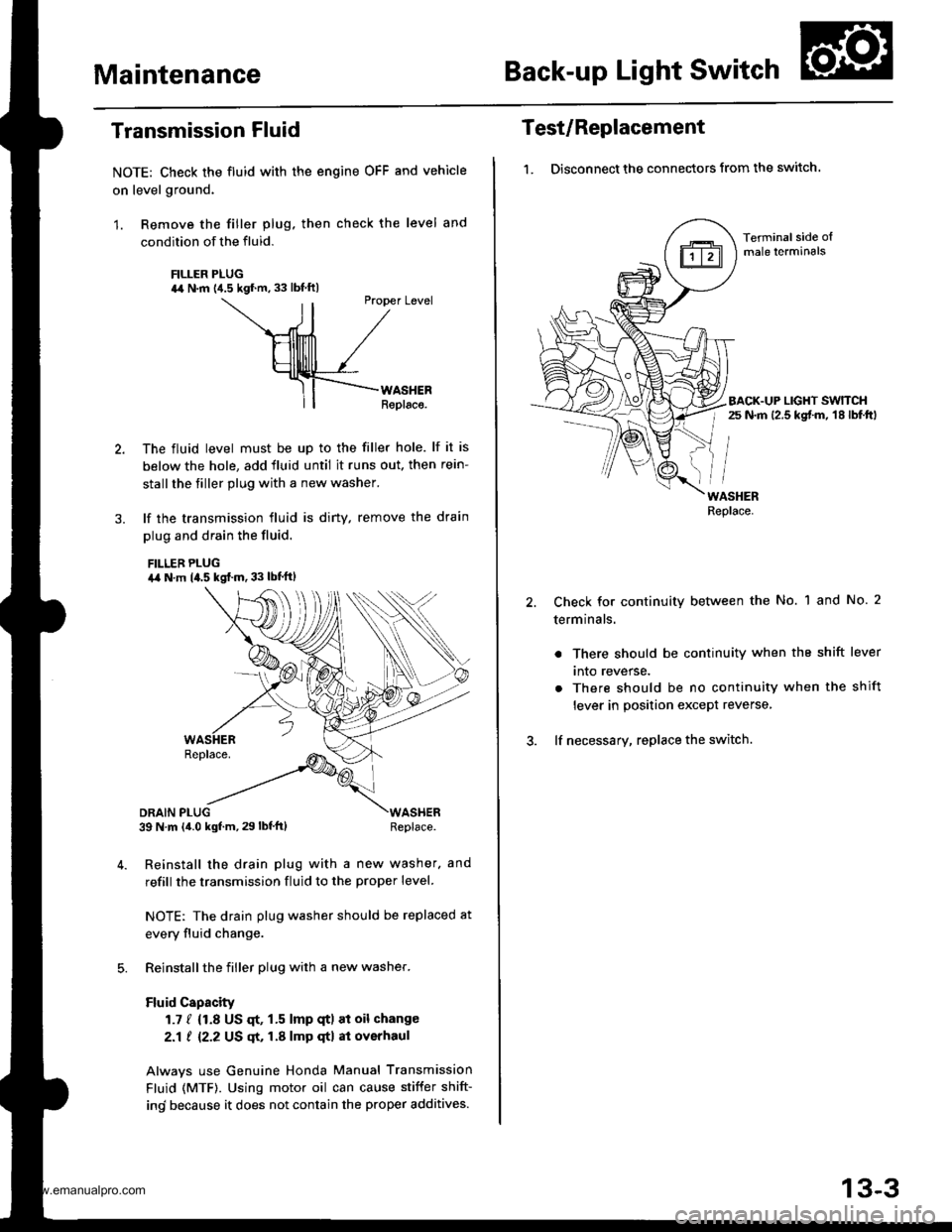
NOTE: Check the fluid with the engine OFF and vehicle
on level ground.
1. Remove the filler plug. then check the level and
condition of the fluid.
FILLER PLUG44 N.m {4.5 kgf.m. 33 lbf ftl
ll
Ptopet Level
\--ril /
HllllllTl /
Hllllrlll /_rf-F{--rno."."
ll| | Replaco.
The fluid level must be up to the filler hole. lf it is
below the hole, add fluid until it runs out. then rein-
stall the tiller plug with a new washer.
lf the transmission fluid is diny, remove the drain
plug and drain the fluid.
FILLEB PLUGa,a N.m 14.5 kgf..n. 33 lbt'ftl
DRAIN PLUG39 N m (4.0 kgf.m, 29 lbf'ft)WASHERReplace.
Reinstall the drain plug with a new washer. and
refill the transmission fluid to the proper level.
NOTE: The drain plug washer should be replaced at
every fluid change.
Reinstall the filler plug with a new washer.
Fluid Capacity
1.7 / {1.8 US qt, 1.5 lmp qtl at oil change
2.1 ! 12.2 US qt, 1.A lmp qtl at overhaul
Alwavs use Genuine Honda Manual Transmission
Fluid (MTF). Using motor oil can cause stiffer shift-
ind because it does not contain the proper additives.
Test/Replacement
1. Disconnect the connectors from the switch.
Terminal side oImale lerminals
BACK.UP LIGHT SWTTCHr 25 N.m 12.5 kgt m, 18 lbf.ftl
WASHERReplace.
Check for continuity between the No. 1 and No. 2
terminals.
. There should be continuity when the shift lever
tnto reverse.
. There should be no continuity when the shift
lever in position except reverse,
lf necessary, replace the switch.
13-3
www.emanualpro.com