Page 1112 of 1395
Troubleshooting
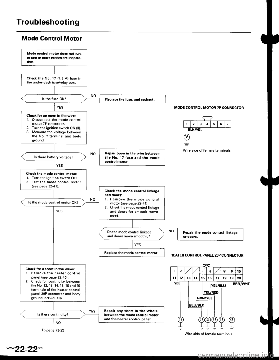
Mode Control Motor
NO
MODE CONTROL MOTOR 7P CONNECTOR
13I5
BLK/YEL
Wire side of female terminals
HEATER CONTROL PANEL 2OP CONNECTOR
BRN/WHT
Wire side of female terminals
Mode control motol does not run.or ono or more modes are inoD€aa-
Check the No. 17 {7.5 A) Iuse inthe under-dash fuse/relay box.
Replace the tus€, snd iecheck.
Chock tor an open in th€ wi.6:1. Disconnect the mode controlmotor 7P connector.2. Turn the ignition switch ON (ll).3. Measure the voltage betweenthe No. l terminal and bodyground.
Repair opon in the wire betwoontho No. 17 luse and tho modecontrol motor.
Check the mode control motor:1. Turn the ignition switch OFF.2. Test the mode control motorGee page 22 41') .
Chock th€ mode cont.ol link.geand doors:1. Remove the mode controlmotor (see page 22-41).2. Check the mode control linkageand doors for smooth move-ment,
ls lhe mode control motor OK?
Do the mode control linkageand doors move smoothly?
Replece the inod6 control motor.
Chock for s shon in the wir€s:1. Remove the heater controlpanel (see page 22'46).2. Check for continuity betweenthe No. 12, 13, 14, 15, 16 and 19terminals ol the heater controlpanel 20P connector and bodyground individuaily.
Repair any short in the wire(slbetween the mode control rnotoaand the h6ater control Danel.
ls there continuity?
2l,/1,/8I10
111213ta151617r81320
BLU
[E!r!
YEL/RED
Ii
To page 22-23
www.emanualpro.com
Page 1114 of 1395
Troubleshooting
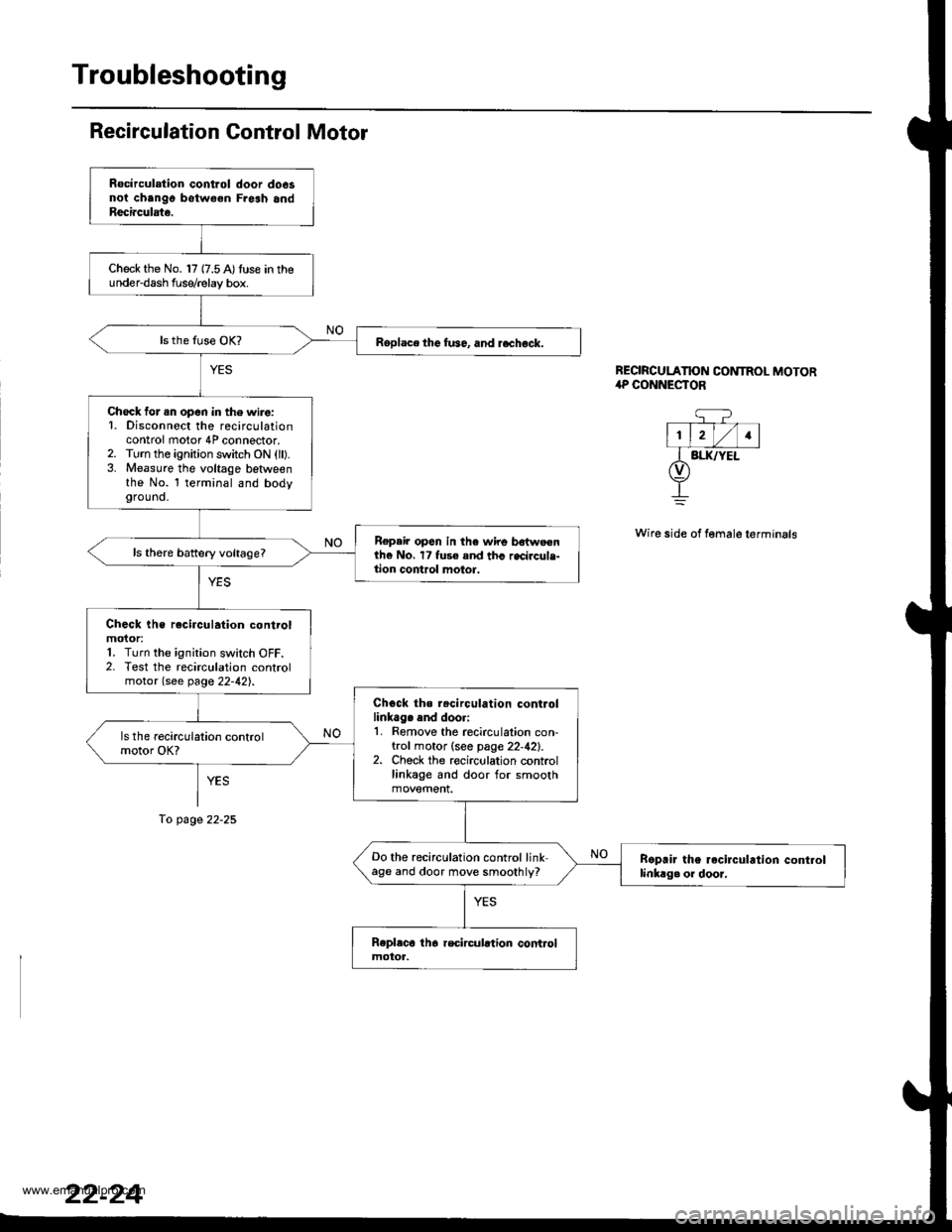
Recirculation Gontrol Motor
YES
To page 22-25
REORCULATION CONTROL MOTOR,rP CONNESTOR
q?- T--- V-l
l1, lrl/l1lI BI.IUYEL(v)
+
Wire side of female terminals
Rocirculation control door do6snoi chango botw€en Fresh andReci.culate.
Check the No. 17 {7.5 A)tuse in theunder-dash f use/relay box.
Roplace the fu36, and rechock.
Check for .n open in the wire:1. Disconnect the recirculationcontrol motor 4P connector.2. Turn the ignition switch ON (ll).3. Measure the voltage betlveenthe No. l terminal and bodyground.
Repair op6n in the wire bdtweenthe No. 17 fuse and thc recircule-tion control motor.
Check the rocirculation controlmoior:1. Turn the ignition switch OFF.2. Test the recirculation controlmotor (see page 22-42).
Chock ths r.circulation controllinkag. end doori1. Remove the recirculation con-trol motor (see page 22,42).2. Check the recirculation controllinkage and door for smooth
Do the recirculation control linkage and door move smoothly?Boprir the recirculrtion controllinkag. or dooJ,
www.emanualpro.com
Page 1115 of 1395
Ftom page 22-24
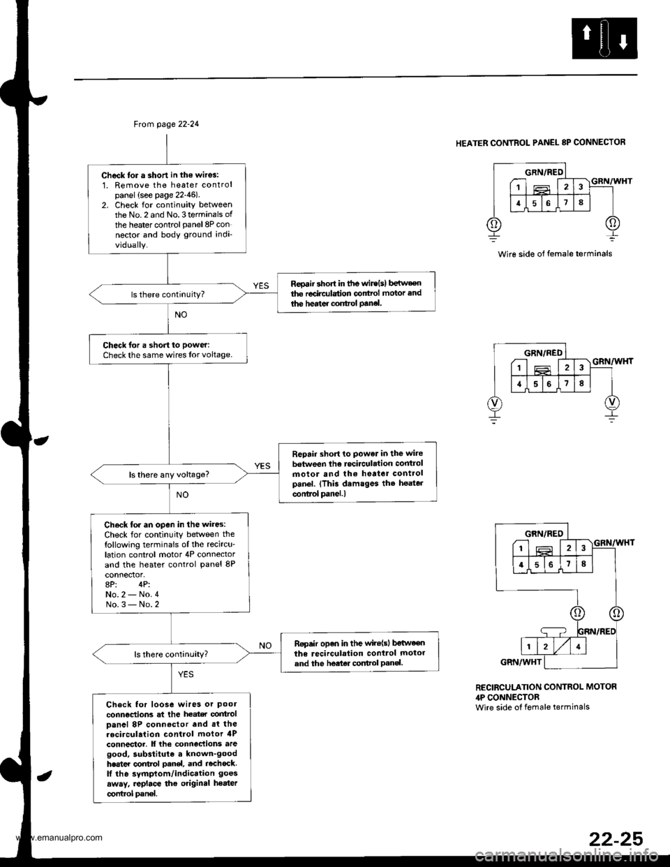
Check tol a short in the wit6:1. Remove the heater controlpanel {see page 22-46)2. Check for continuity betweenthe No.2 and No.3terminals of
the heater controlpanel8P connector and body ground indi-vidually.
Reoaii short in tfte wir€{s) b€irv€€nthe redrc{lstion conttol motor and
ihe hedter control panel.
Check for a shon to power:
Check the same wires lor voltage.
Repair short to power in the wite
between the rocirculation controlmotor and lh€ heator controlpanel. (This demsges the heater
conlrol panel.l
ls there any voltage?
Ch€ck tor an open in the wires:Check for continuity between thefollowing terminals ol the recircu'lation control motor 4P connectorand the heater control panel 8P
8P: 4P:No.2 - No.4No.3- No.2
Ropair open in the wile(sl betweenthe recirculalion control motorand the heeter cortrol Pan€|.
Check for loose wires or pool
connections at the heat€r control
Danel 8P connoctor and .t therocirculation control motor 4Pconnector. lf lhe connec{ions aregood, substitule a known-goodhester control oanel, and rochock.lI the symptom/indication goes
away, .eplace the otiginal heater
control pan€|.
HEATER CONTROL PANEL 8P CONNECTOR
Wire side of female terminals
GRN/REO---1 T'lF Iir l516 I
213
;T;
1ffiIVI4I
GRN/WHT
RECIRCULATION CONTROL MOTOR,lP CONNECTORwire side ot female terminals
22-25
www.emanualpro.com
Page 1117 of 1395
Ch6ck for an open in the wire:1. Disconnect the jumper wire.
2. Disconnect the radiator fan 2P
3. Check for continuity beNveenthe No. l terminal o{the radia-tor fan relay 4P socket and theNo. 2 terminal of the radia'tor fan 2P connector-
Repai. open in the wira betweenthe radiator fan .olay ,nd the radi'atorfan.
Check lor an open in the wi.e:Check for continuity between theNo. 1 terminal oI the radiator fan2P connector and body ground.
Check lor an open in the wir.
b€turosn the radi.tor fan and bodyground. lf ihe wire b OK, check folpoor ground .t G2()l .
ls there continuity?
Replace the radiator tan motor.
Ftom page 22-26
RADIATOR FAN REI-AY 4P SOCKET
BLK/RED
RADIATOR FAN 2P CONNECTORWire side of lemale terminals
(cont'd)
www.emanualpro.com
Page 1120 of 1395
Troubleshooting
Condenser Fan {cont'd)
CONDENSER FAN RELAY 4P SOCKET
r---------t wHT
lr_f__l12 | |
fT;.] |I/Or\j/
I
G
CONDENSER FAN 2P CONNECTORWire side ol temale torminals
-r+-,.12
TBtK
@
!
Chock for an open in the wire:'1. Disconnect the iumper wire.2. Disconnect the condenser fan2P connector.3. Check for continuity betweenthe No. 1 terminal of the con,denser fan relay 4P socket andthe No. 2 terminal of the con-denser fan 2P connector.
Ropair open in the wire betwoenth€ condenser fan rslay and thecondenser tan.
ls there continuity?
Chech tor an open in the wire:Check for continuity between theNo. I terminal of the condenserfan 2P connector and bodyground.
Check for an open in thg wirebetween the condenser fan andbody ground. lf the wiro is OK.check tor poor ground .t G202.
Replace tho condenser tan motor.
22-30
www.emanualpro.com
Page 1130 of 1395
Troubleshooting
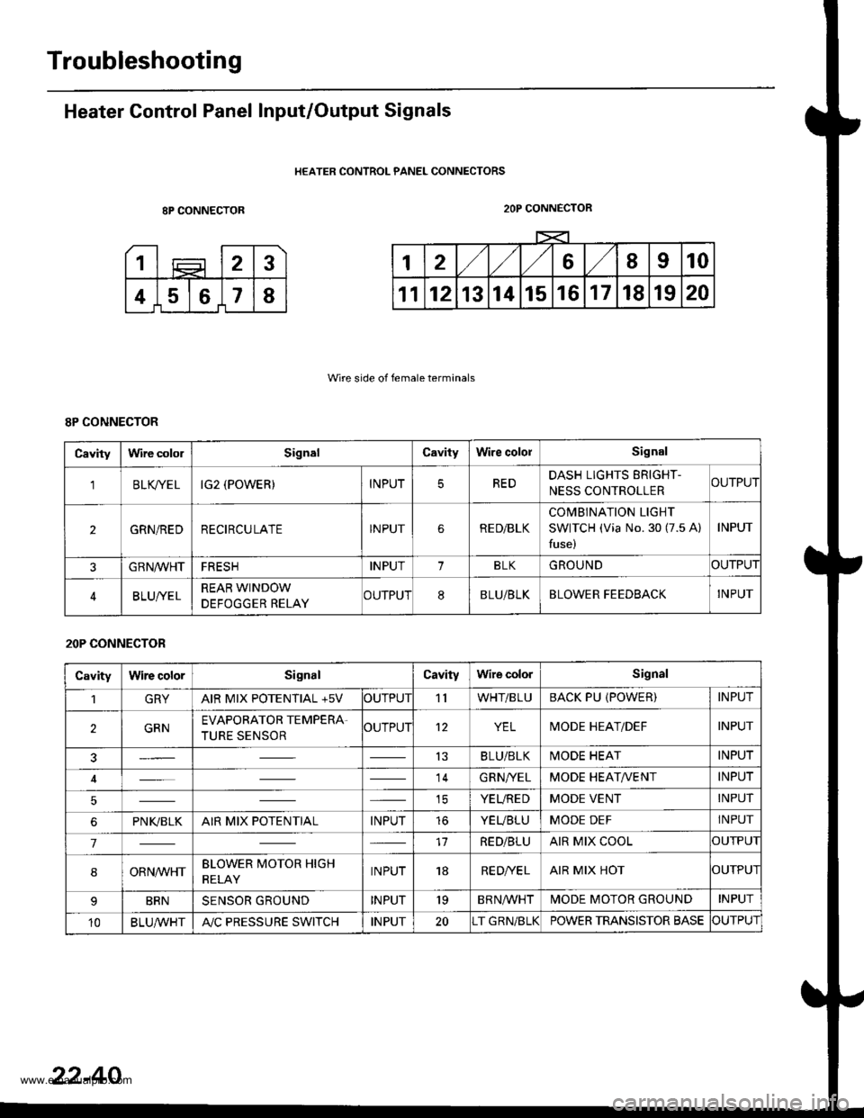
Heater Control Panel Input/Output Signals
HEATER CONTROL PANEL CONNECTORS
8P CONNECTOR
Wire side of female terminals
2OP CONNECTOR
8P CONNECTOR
Cavitylrvire cololSignalCavityWire cololSignal
'lBLK/TE LIG2 (POWER)INPUTREDDASH LIGHTS ERIGHT-
NESS CONTROLLERCUTPUT
2GRN/REDRECIRCULATEINPUTRE D/BLK
COMBINATION LIGHT
SWITCH (Via No. 30 (7.5 A)
fuse)
INPUT
GRN/VVHTFRESHINPUT1BLKGROUNDOUTPUT
BLUI/ELREAR WINDOW
DEFOGGER RELAYCUTPUT8BLU/BLKBLOWER FEEDBACKINPUT
20P CONNECTOR
CavityWire colorSignalCavityWire colorSignal
1GRYAIR MIX POTENTIAL +5VOUTPUT'llWHT/BLUBACK PU (POWER)INPUT
2GRNEVAPORATOR TEMPERA.
TURE SENSOROUTPUT12YELMODE HEAT/DEFINPUT
13BLU/BLKMODE HEATINPUT
14GRN/YELMODE HEAT/VENTINPUT
ICYEUREDMODE VENTINPUT
6PNI(BLKAIR MIX POTENTIALINPUTtoYEUBLUMODE DEFINPUT
717RED/BLUAIR MIX COOLOUTPUI
8ORNrur'HTBLOWER MOTOR HIGH
RELAYINPUT18RE D/VE LAIR MIX HOTOUTPUI
BRNSENSOR GROUNDINPUT'19BRNA/VHTIVIODE MOTOR GROUNDINPUT
10BLU,ryVHTA"/C PRESSURE SWITCHINPUT20T GRN/BLKPOWER TRANSISTOR BASECUTPUT
22-40
www.emanualpro.com
Page 1131 of 1395
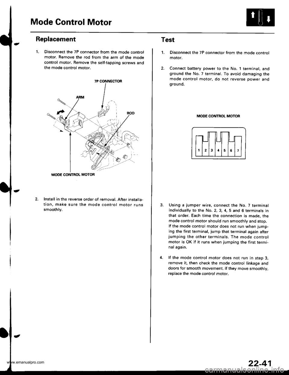
Mode Control Motor
Replacement
1. Disconnect the 7P connector from the mode control
motor. Remove the rod from the arm of the mode
control motor, Remove the self-tapping screws and
the mode control motor.
2.Install in the reveGe order of removal. After installa-
tion, make sure the mode control motor runssmoothlv.
7P CONNECTOR
MODE CONTROL MOTOR
Test
1.Disconnect the 7P connector from the mode control
motor.
Connect battery power to the No. 1 terminal, andground the No. 7 terminal. To avoid damaging the
mode control motor, do not reverse power andgrouno.
MODE CONTROL MOTOR
Using a jumper wire. connect the No. 7 terminalindividually to the No, 2,3, 4,5 and 6 terminals in
that order. Each time the connection is made. the
mode control motor should run smoothly and stop.
lf the mode control motor does not run when jump-
ing the first terminal, jump that terminal again afterjumping the other terminals. The mode control
motor is OK it it runs when jumping the first termi-
nal again.
lf the mode control motor does not run in step 3,remove it, then check the mode control linkage and
doors for smooth movement. lf they move smoothly,
reDlace the mode control motor.
www.emanualpro.com
Page 1132 of 1395
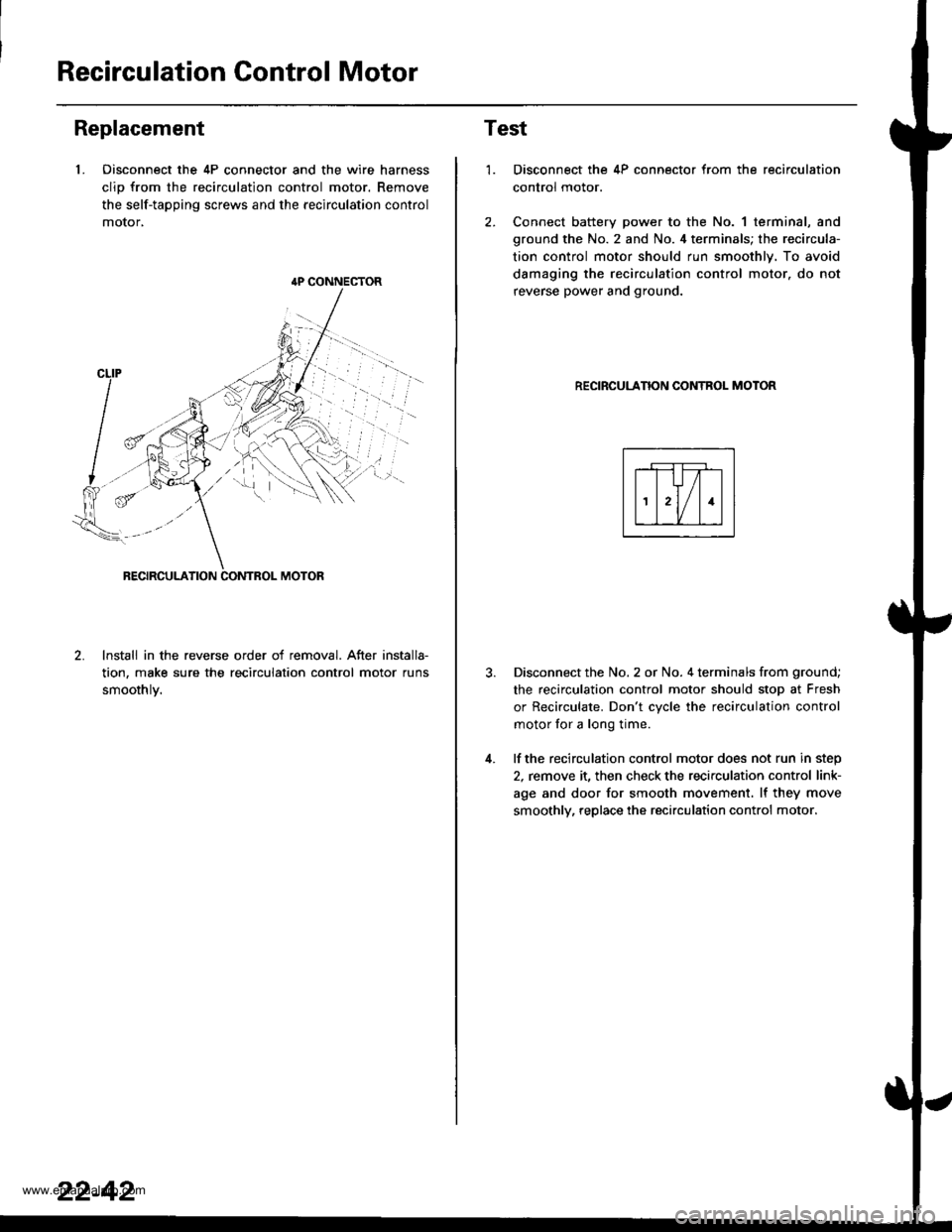
Recirculation Control Motor
Replacement
1. Oisconnect the 4P connector and the wire harness
clio from the recirculation control motor. Remove
the self-tapping screws and the recirculation control
motor,
lnstall in the reverse order of removal. After installa-
tion, make sure the recirculation control motor runs
smoothlv.
{P CONNECTOR
22-42
Test
1.
4.
Disconnect the 4P connector from the recirculation
control motor.
Connect battery power to the No. 1 terminal, and
ground the No. 2 and No. 4 terminals; the recircula-
tion control motor should run smoothly. To avoid
damaging the recirculation control motor. do not
reverse power and ground.
RECIRCULANON CONTROL MOTOR
Disconnect the No. 2 or No. 4 terminals from ground;
the recirculation control motor should stop at Fresh
or Recirculate. Don't cvcle the recirculation control
motor for a long time.
lf the recirculation control motor does not run in step
2, remove it, then check the recirculation control link-
age and door for smooth movement. lf they move
smoothly, replace the recirculation control motor.
www.emanualpro.com