Page 671 of 1395

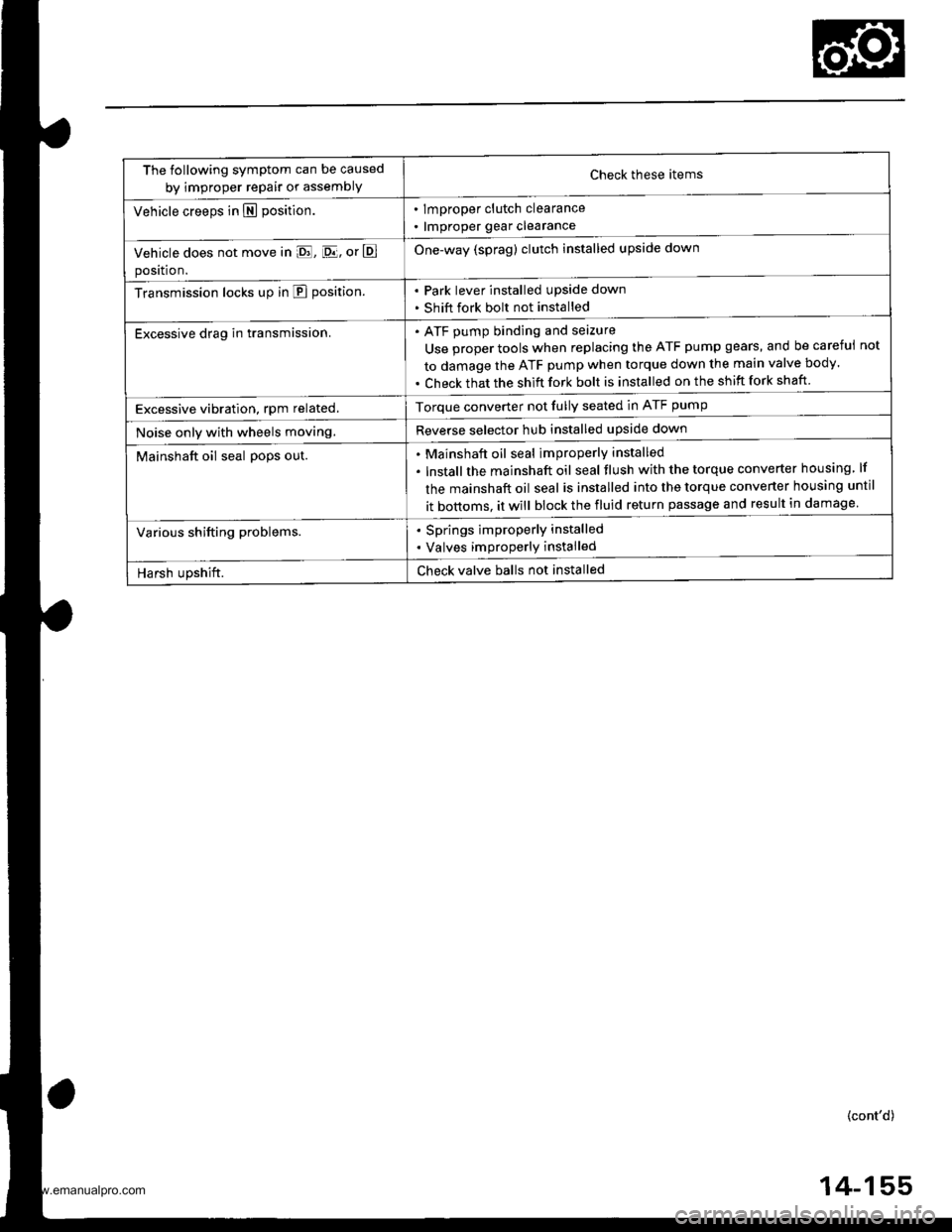
The following symptom can be caused
by improper repair or assemblYCheck these items
. lmproper clutch clearance
. lmproper gear clearance
One-way (sprag) clutch installed upside down
Park lever installed upside down
Shift fork bolt not installed
Vehicle creeps in N position.
Vehicle does not move in E, [D.lj, or E
position.
Transmission locks up in E position.
Excessive drag in transmission.ATF pump binding and seizure
Use proper tools when replacing the ATF pump gears, and be careful
to damage the ATF pump when torque down the main valve body.
Check that the shift fork bolt is installed on the shift fork shaft
not
Excessive vibration, rpm related.Torque converter not fully seated in ATF pump
Reverse selector hub installed upside downNoise only with wheels moving.
Mainshaft oil seal po9s out.Mainshaft oil seal improperly installed
lnstallthe mainshaft oil seal tlush with the torque converter housing lf
the mainshaft oil seal is installed into the torque converter housing until
it bottoms. it will block the fluid return passage and result in damage
Various shifting problems.. Springs improperly installed
. Valves improperly installed
Harsh upshift.Check valve balls not installed
(cont'd)
4-155
www.emanualpro.com
Page 683 of 1395
lnstallation
Install a new O-ring on ths transfer assembly.
Clsan the areas where the transfer assembly con-
tacts the transmission with solvent or carburetor
cleaner, and dry with compressed air. Then apply
ATF to the contact areas.
Install the transter assembly on the transmission.
NOTE: while installing the transfer assembly, do
not allow dust or other foreign particles to enter the
transmission.
lnstall the rear stiffener.
1.
8 r 1.25 mm24 N.m {2.4 kgf m,
r7 bl.ftl
TNANSFERASSEMALY
10 x'l.25 mmara N.m 14.5 kgtm,33 tbf trl
O.RING
5. Install the propeller shaft to the transfer assembly
by aligning the reference marks
PROPELLERSHAFT
8 xl,25 ]nm32 N.m (3.3 kgl.m,2a tbf.ftlReplace.
Install the shift cable with the control pin, then
secure it with the snap pin. Do not bend the shift
cable excessively.
lnstallthe shift cable cover.
SHIFT CABLE
7.
8 xl.25 mm22 N.m 12.2 kd-m,16 tbt.ftl
(cont'd)
REFERENCE MARKS
14-167
www.emanualpro.com
Page 685 of 1395

Transmission
Removal
@
2.
'1.
Make sure lifts. iacks, and safety stands aro placed
properly, and hoist brackets are attached to the col-
rest position on the engine lsee section 11.
Apply th€ parking brake and block the r€ar wheels,
so vehicls will noi roll off the stands and fall on you
while working under it.
NOTE: Use fender covers to avoid damaging painted
surfaces.
Disconnect the negative terminal, then disconnect
the positive terminal from the battery.
Remove the intake air duct and the air cleaner hous-
ing assembly,
Remove the starter cables. Remove the harness
clamp from the clamp bracket.
5.
STARTERCABLES
Remove the transmission ground cable terminal
and the radiator hose clamp lrom the transmission
hanger.
Disconnect the lock-up control solenoid valve con-
nector, then remove the harness clamp from the
clamp bracket.HARNESS CLAMP
RADIATOR HOSECLAMP
CONTROLSOLENOID VALVECONNECTOR
CLAMP
6. Disconnect the vehicle speed sensor (VSS), the coun-
tershaft speed sensor, and the A/T gear position
switch connectors.
A/T GEAR POSITIONSWITCH CONNECTOR
VEHICLE SPEEDSENSOR |VSS'
CONNECTORBfiACKET
SPEED SENSORCONNECTOR
7. Remove the transmission housing mounting bolts.
MOUNTING BOLTS
(cont'd)
14-169
www.emanualpro.com
Page 702 of 1395

End Cover
Removal
NOTE:
o The illustration shows the 4WD automatic transmission; the 2WD is similar.. cleanall parts thoroughly in solvent or carburetor cleaner, and drythem with compressed air.. Blow out all passages.
. When removing the transmission end cover, replace the following:- End cover gasket- Lock washer- O-rings- Shaft locknuts- Conical spring washers- Sealing washers
END COVER GASKET
MAINSHAFT LOCKNUT
CONICAL SPRING WASHER
6 x 1 .0 rhm EOLTS
PARK PAWL
A/T GEAR POSMONSwlTCH COVER
NEEDI.T BEARING
SUB.SHAFT LOCKNUT
CONICAL SPRINGWASHER
LINE AOLT
ATF COOI.f B LINES
14-186
PAwL 7// Locx wASHER
'sHAFr 9/ ?ARK srop
o-- Ay' couNTERsHAFr
G-€ LocKNUr!€ / ..t,"o, "oo
A/T GEAR POSMONSW|TCH HARNESS CLAMP
CONICAL SPRINGWASHCR
A/T GEAR POSITION
PARK GEAR
Y CLUTCH
lST GEAR
NEEDLE BEARING
1ST CLUTCH ASSEMBLY
THRUST WASHER
THRUST NEEDLE AEARING
O.RINGS
\\
SUB.SHAFT 1ST GEAR
MAINSHAF? 'ST GEAR
MAINSHAFT 1STGEAR COLLAR
SEALING WASHERS
!€'-l
I"EVERSPRING
COUNTERSHAFTlST GEAR COLLAR
PAWL
lt1/ sroe
Y plwl f
L/'SPRING
LOCKNUT
LINE BOLTSEALING WASHERS
www.emanualpro.com
Page 704 of 1395
Transmission Housing
Removal
NOTE:
. The illustration shows the 4WD automatic transmission; the 2WD is similar,. Cleanall parts thoroughly in solvent or carburetor cleaner. and drythemwith compressed air.. Blow out all passages.
. When removing the transmission housing, replace the lollowing:- Transmission housing gasket- Lock washer- O-rings
TRANSMISSION HANGERTRANSMISSION HOUSING
REVERSE GEAN COLLAR
TRANSMISSION HOUSING MOUNTING EOLT
CONNECTOR BRACKET
MAINSHAFT SPEEDSENSOR
REVERSE GEAR
LOCK WASHER
REVERSE SHIFT
MAINSHAFTSUB.ASSEMBLY
TRANSMISSION HOUSINGGASKET
DIFFERENTIAL ASSEMBLY
TOROUE CONVERTER HOUSINGO-RINGt4wDl
TRANSFER ASSEMBLYt4wDt
10 x 1.25 mm
l4wo)
14-1 88
BOLTS
www.emanualpro.com
Page 706 of 1395
Torque Converter Housing/Valve Body
Removal
NOTE:
. The illustration shows the 4WD automatic transmission; the 2WD is similar.' cleanall parts thoroughry in sorvent or carburetor creaner, and drythem with compressed air.. Blow out all passages.
. When removing the valve bodies, replace the following:- Lock washer- O-ringATF FEED PIPESERVO DETENTBASE137 - 98 models only)
DOWEL PIN
LOCK.UP VALVEBOOY
6x1.0mm'97 - 98 models:2 Bolts'99 - 00 modeb: 1 Bolt
LOCK.UP SEPARAPLATE
REGULAIOR VALVEBOOY
ATFSTRAINER
DOWEL PIN
COOLER RELIEF VALVE
6x1.0mm37 - 98 models:7 Bolts'gg - 0O models:8 Bolts
SERVO BODY137 - 98 modelsl
SERVOSEPARATORPLATE
TOROUE CONVERTERCHECK VALVE
STATOR SHAFT
O.RING
5x1.0mfi3 Bolts
SECONDARYVALVE BODY
MAIN VALVE BODY
6x 1.05 Bolts
ATF PUMP ORIVENGEAR SHAFT
DOWEL PIN
ATF PUMP DRIVENGEAR
\
CONTROL LEVERMOUNTING BOLT{awD)
SECONDARYSEPARATORPLATE
14-190
www.emanualpro.com
Page 707 of 1395

1.Remove the control lever mounting bolt trom the
torque converter side of the torque converter hous-
ing. (4WD)
Remove the ATF feed pipes from the servo body,
secondary valve body, lock-up valve body, and main
valve body.
For '97 - 98 models:
Remove the two bolts securing the ATF strainer and
servo detent base, then remove the strainer and the
base.
For'99 - 00 models;
Remove the ATF strainer {one bolt).
4. For'97 - 98 models:
Remove the seven bolts securing the servo body,
then remove the servo body and separator plate'
For'99 - 00 models:
Remove the eight bolts securing the servo body,
then remove the servo body and separator plate'
5. Bemove the three bolts securing the secondary
valve body, then remove the secondary valve body'
stop shaft bracket, and separator plate.
6. Remove the eight bolts securing the ATF lubrication
plate and lock-up valve body, then remove the ATF
lubrication plate, lock-up valve body' and separator
plate.
7. Remove the one bolt securing the regulator valve
body, then remove the regulator valve body'
8. Remove the stator shaft and stop shaft.
9. Remove the detent spring from the detent arm, then
remove the control shaft from the torque converter
houslng.
10. Remove the detent arm and detent arm shaft from
the main valve body.
11. Remove the five bolts securing the main valve
body, then remove the main valve body.
When removing the main valve body, do not let the
eight check balls fall out.
12. Remove the ATF pump driven gear shaft, then
remove the ATF PumP gears.
13. Remove the main separator plate with two dowel
prns.
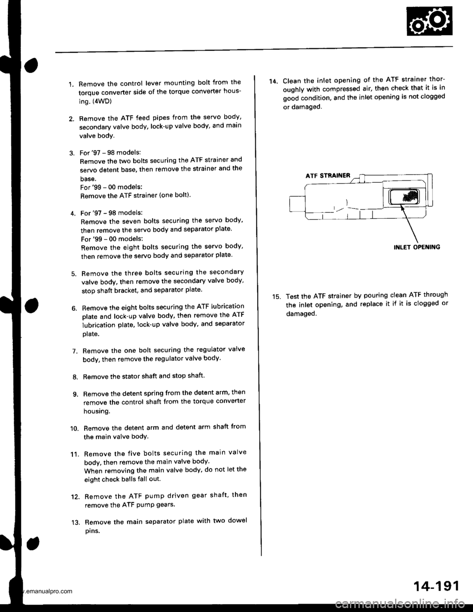
14, Clean the inlet opening of the ATF strainer thor-
oughly with compressed air, then check that it is in
good condition, and the inlet opening is not clogged
or damaged.
15.
INLET OPENING
Test the ATF strainer by pouring clean ATF through
the inlet opening, and replace it if it is clogged or
damaged.
14-191
www.emanualpro.com
Page 712 of 1395
Main Valve Body
Disassembly/lnspection/Reassembly
NOTE:
. Do not use a magnet to remove the check balls; it may magnetize the balls.t clean all parts thoroughly in solvent or carburetor cleaner, and dry them with compressed ai.. Blow out all passages.. Replace the valve body as an assembly if any parts are worn or damageo.. Checkall valvesforfree movement. lfanyfailtoslidefreely,seeValveBodyRepaironpage.t4_192.. Coat all parts with ATF during reassembly.
VALVE CAP CLIP
2ND ORIFICE CONTROL VALVE
SPRING SEAT
BALLS, 8
ACCUMULATOR CHOKE
VAI-VE
FELI€F VALVE
@
UK
MAIN VALVE BOOYInspect for wear, scratches,and sconng.
sERVO CONInOL
:,/\^._.^,
I-2 SHIFT VALVE
14-196
www.emanualpro.com