1997 HONDA CR-V ignition wire
[x] Cancel search: ignition wirePage 74 of 1395

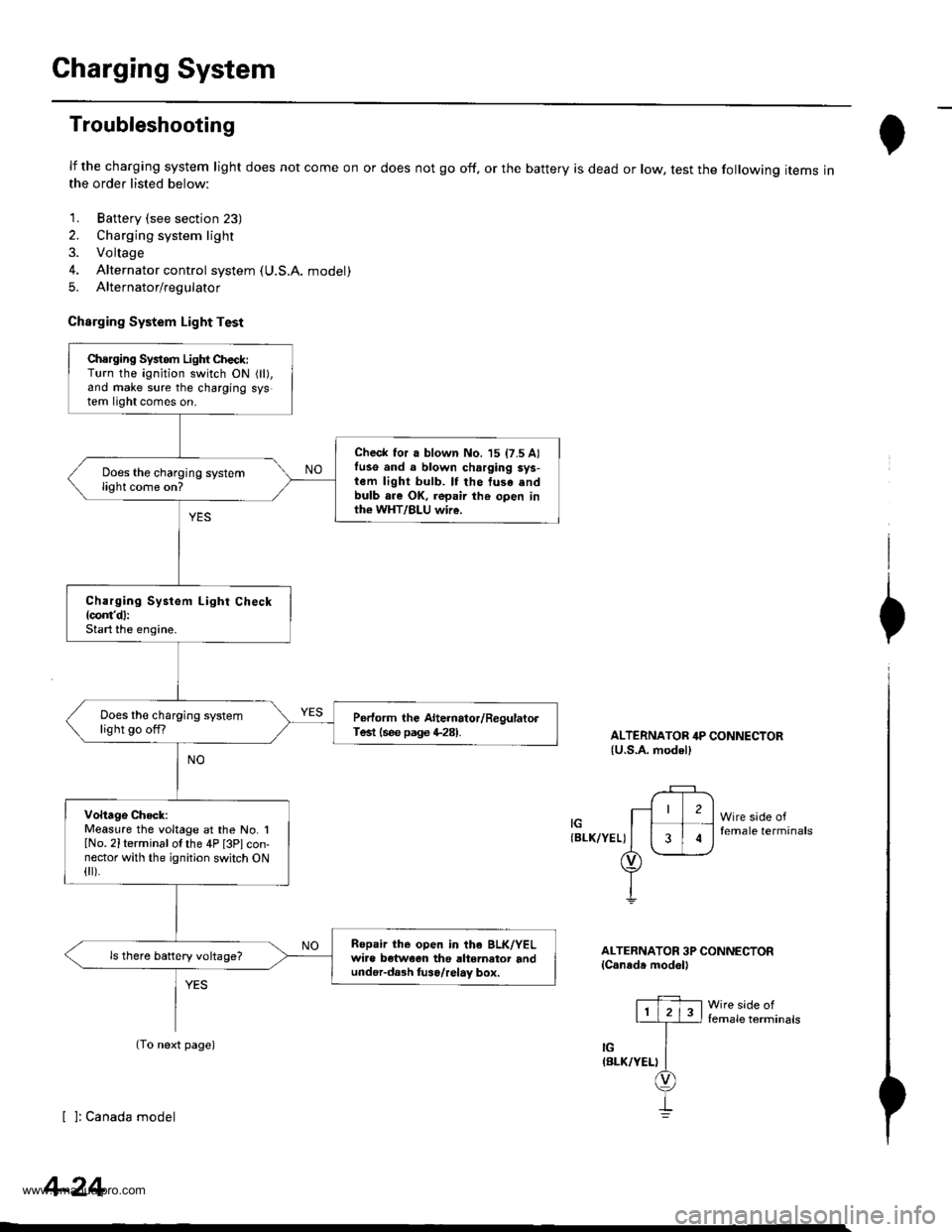
Gharging System
Troubleshooting
lf the charging system light does not come on or does not go off, or the battery is dead or low, test the following items inthe order listed below:
1. Battery (see section 23)
2. Charging system light
3. Voltage
4. Alternator control system (U.S.A. model)
5. Alternator/regulator
Charging System Light Test
ALTERNATOR 4P CONNECTOR{U.S,A. modell
(BLK/YEL)
2
3
Wire sade offemale terminals
I
I
I
ALTERNATOR 3P CONNECTORlCaneda model'
Iemale terminals
[ ]: Canada model
Chsrging Systom Light Check:Turn the ignition switch ON {ll),and make sure the charging system light comes on.
Check for a blown No. 15 17.5 Alfuse and a blown charging sys-tem light bulb. lf the tusa .ndbulb are OK, repair th€ open inth€ WHT/BLU wire.
Does the charging systemlight come on?
Charging System Light Check{com'd}:Start the engine.
Does the charging systemlight go offfPerform the Alte.nator/RegulatorTest lsee page +281.
Voltage Check:Measure the voltage at the No. IlNo. 2iterminal of the 4P [3Plcon-nector with the ignition switch ON{ ).
Ropair the open in the BLK/YELwiae betwoen the altemator andunder-da3h luso/relay box.
ls there battery voltage?
(To next page)
4-24
www.emanualpro.com
Page 75 of 1395
![HONDA CR-V 1997 RD1-RD3 / 1.G Workshop Manual
in(From previous page)
Does the charging systemlight come on?
Ch6ck the L circuil:1. Turn the ignition switch OFF.2. Disconnect the 4P [3P] con-nector from the alternator.3. Turn the ignition switch HONDA CR-V 1997 RD1-RD3 / 1.G Workshop Manual
in(From previous page)
Does the charging systemlight come on?
Ch6ck the L circuil:1. Turn the ignition switch OFF.2. Disconnect the 4P [3P] con-nector from the alternator.3. Turn the ignition switch](/manual-img/13/5778/w960_5778-74.png)
in(From previous page)
Does the charging systemlight come on?
Ch6ck the L circuil:1. Turn the ignition switch OFF.2. Disconnect the 4P [3P] con-nector from the alternator.3. Turn the ignition switch ON (ll).
Repair the short to ground in theWHT/BLU wire.
[ ]: Canada model(cont'd)
4-25
www.emanualpro.com
Page 203 of 1395

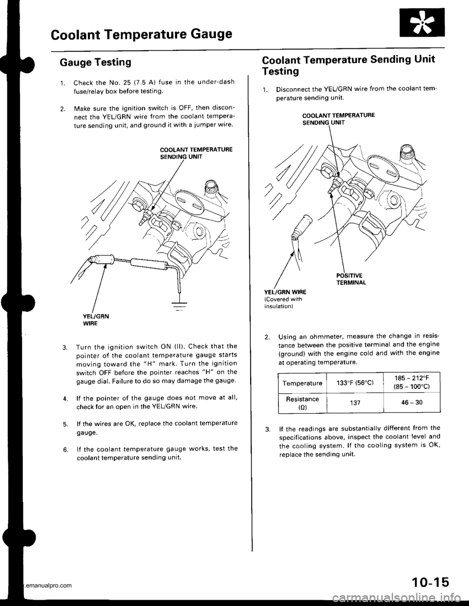
Goolant Temperature Gauge
Gauge Testing
1. Check the No. 25 (7.5 A) fuse in the under-dash
fuse/relay box before testin9.
2. Make sure the ignition switch is OFF, then discon-
nect the YEL/GRN wire from the coolant tempera-
ture sending unit. and ground it with a jumper wire.
YEL/GRNWIRE
Turn the ignition switch ON {ll). Check that the
pointer of the coolant temperature gauge starts
moving toward the "H" mark. Turn the ignition
switch OFF before the pointer reaches "H" on the
gauge dial. Failure to do so may damage the gauge.
lf the pointer of the gauge does not move at all,
check for an open in the YEL/GRN wire.
lf the wires are OK, replace the coolant temperature
gauge.
lf the coolant temperature gauge works, test the
coolant temperature sending unit.
5.
COOLANT TEMPERATURE
Coolant Temperature Sending Unit
Testing
1. Disconnect the YEUGRN wire from the coolant tem
perature sending unit.
COOLANT TEMPERATURE
POSITIVETERMINAL
YEL/GRN WIRE(Covered withinsulation)
2. Using an ohmmeter, measure the change in resis-
tance between the positive terminal and the engine
(ground) with the engine cold and with the engine
at operating temPerature.
Temperature133.F (56'C)1A5 - 212F
(8s - 100'c)
Resistance(0)13746-30
3. lf the readings are substantially different from the
specitications above, inspect the coolant level and
the cooling system. lf the cooling system is OK,
replace the sending unit.
10-15
www.emanualpro.com
Page 269 of 1395

Powertrain Control Module Terminal Arrangement -'97 Model
FCM CONNECTOR A (32P)NOTE: Standard battery voltage is 12 V.
Wire side of lemale terminals
f€rminalnumlreJWirecolor
Telminalnama
DescriptionSignal
YELlNJ4 (No.4 FUELINJECTOR)Drives No. 4 {uel injector.With engine running: duty controlled
2BLUlNJ3 (No.3 FUELINJECTOR)Drives No. 3luel injector.
REDlNJ2 {No.2 FUELINJECTOR)Drives No.2 tuel injector.
BRNlNJl (No. l FUELINJECTOR)Drives No. 1 fuel injector.
5BLK WHTSO2SHIC (SECONDARY
HEATED OXYGEN SENSOR HEATER CONTROL)
D ves secondary heated oxygensensor heater.With ignition switch ON {ll): battery voltageWith fully warmed up engino running: dutycontrolled
6BLKAr'YHT
PO2SHTC (PRIMARY
HEATED OXYGENSENSOR HEATERCONTROL}
Drives primary heated oxygensensor heater,With ignition switch ON lll): battery voltagewith fully warmed up engine running: dutycontroll6d
I8RN/BLKLGl (LOGIC GROUND}Ground forthe PCM control circuit.Less than 1.0 V at all times
10BLKPG1 lPOWER GROUND}Ground for the PCM power circuit.
l1YEUELKIGPl lPOWER SOURCE}Power source for the PCM controlcircuit.
With ignition switch ON (ll): battery voltageWith ignition switch OFF: 0 V
12BLI(BLUIACV {IDLE AIRCONTROL VALVE}Drives IACV.With €ngine running: duty controlled
REDryEL
PCS (EVAP PURGECONTFOL SOLENOIDVALVE)
Drives EVAP purge controlsolenoid valve.
With engine running, engine coolantbelow 154'F (68"C): battery voltageWith engine running, engine coolantabove 154"F (68"C): duty controlled
16GRN/VELFLR (FUEL PUMP RELAY)Drives Iuel pump relay.0 V for two seconds after turning ignition
switch ON lll), then battery voltage
118LI(REDACC (A,/C CLUTCHRELAY}Drives Ay'C clutch relay.With comoressor ON: 0 VWith compressor OFF: baftery voltage
18GRN/ORNMIL (MALFUNCTION
INDICATOR LAMP}Drives MlL.With MIL turned ON: 0 VWith MIL turned OFF: baftery voltage
19*WHT/GRNALTC (ALTERNATOR
CONTROL}Sends alternator control signal.With tully warmed-up engine running:
battery voltageDuring driving with smallelectrical load:0 '
20YEUGRNICM (IGNITION CONTROLMODULE)Sends ignition pulse.With ignition switch ON (ll): baftery voltageWith engine running: pulses
22BRN/BLKLG2 (LOGIC GROUND}Ground tor the PCM control circuit.Less than 1.0 V at alltimes
23BLKPG2 {POWER GROUND}Ground lor the PCM power circuit.
24YEUBLKIGP2 {POWER SOURCE}Power source for the PCM controlcircuit.
With ignition switch ON (ll): battery voltage
With engine switch OFF: 0 V
27GRNFANC (RADIATOR FANCONTROL)Drives radiator {an relay.With radiator fan running: 0 VWith radiator fan stopped: baftery voltage
*: USA
{cont'd)
11-67
www.emanualpro.com
Page 270 of 1395

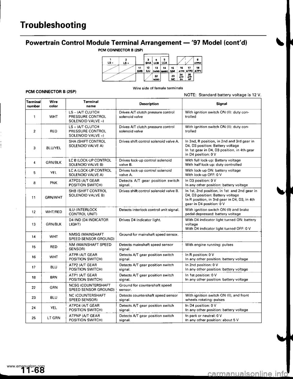
Troubleshooting
PCM CONNECTOR B I25PI
Powertrain Control Module Terminal Arrangement -'97 Model (cont'dl
Wire side of female terminalsPCM CONNECTOR B I25P}NOTE: Standard battery voltage is l2 V.
1 1-68L
TerminelnumbercolorTerminalnameOescriptionSignal
1LS 1A/T CLUTCHPRESSURE CONTROLSOLENOID VALVE -)
Drives A,/T clutch pressure controlsolenoid valveWith ignition switch ON (ll): duty con-trolled
2REDLS + (A"/T CLUTCHPRESSURE CONTROLSOLENOID VALVE +)
Drives A,/T clutch pressure controlsolenoid valveWith ignition switch ON (ll)r duty controlled
38LU//EL
SHA (SHIFT CONTROLSOLENOID VALVE A)Drives shift control solenoid valve A.In 2nd, R position. in 2nd and 3rd gear inD4, D3 position: Battery voltageIn lst gear in D4, D3 position, in 4th gear
in D4 position: 0 V
4GRN/BLKLC B (LOCK-UP CONTFOLSOLENOID VALVE B)Drives lock-up control solenoidvalve B,With full lock-up; Baftery voltageWith half lock-up: duty controlled
5YELLC A (LOCK.UP CONTROLSOLENOID VALVE A)Drives lock-up control solenoidWith lock'up ON: battery voltageWith lock-up OFF:0 V
IPNKATPD3 (Ay'T GEARPOSITION SWITCH}Detects A/T gear position switchsignal. _
In D3 position:0 Vln any other position: battery voltage
11GRN/VVHT
SHB (SHIFT CONTROLSOLENOID VALVE 8}Drives shift control solenoid valve B.In 1st, 2nd position, in 1st and 2nd gear inD4, D3 position: Battery voltageIn R position, ;n 3rd gear in 04, D3, in 4thgear in D4 position: 0 V
12WHT/BEDILU (INTERLOCK
CONTROL UNITiDetects interlock control unh signal.With ignition switch ON (ll)and brakepedal depressed: battery voltage
GRN/BLKD4IND (04 INDICATORLIGHT}Drives Dl indicator light.With D4 indicator light turned ON: batteryvoltageWith D4 indicator light turned OFF: 0 V
14NMSG (MAINSHAFT
SPEED SENSOR GROUND}Ground tor mainshaft speed sensor.
REDNM (MAINSHAFT SPEEDSENSOR)Detects mainshaft speed sensorsrgnal,With engine running: pulses
16ATPR (A"/T GEARPOSITION SWITCH)Detects A/T gear position switchsrgnal.InRposition:0VIn any other position: battery voltage
1'lBLUATP2 (A./T GEARPOSITION SWITCH)Detects A/T gear position switchsrg nal,In 2nd position: 0 VIn any other position: battery voltage
18BRNATP1 (4,,/T GEARPOSTTTON SWTTCH)Detects A/T gear position switchsrg nal,ln lst position: 0 VIn any other position: battery voltage
22GBNNCSG (COUNTERSHAFT
SPEED SENSOR GROUND)Ground tor countershaft speedsensor,
23BLUNC (COUNTERSHAFT
SPEED SENSOR)Detects countershaft speed sensorsrgnal.With agnition switch ON (ll), and lrontwheels rotating: pulses
24YELATPD4 (M GEARPOSITION SWITCH)Detects A,/T gear position switchsrgnal.In D4 positionr 0 VIn any other position: battery voltage
25LT GRNATPNP {A/T GEARPOSITION SWITCH)Detects A/T gear position switchsignal.In park or neutral:0 VIn any other position: about 5 V
www.emanualpro.com
Page 271 of 1395

PCM CONNECTOR C (31PI
ferminalnumberWirecolorTerminalnameDoscriptionSignal
'tBLUiREDCKFP (CKF SENSOR PSIDE)Detects CKF sensor.With engine running: pulses
2BLUCKPP (CKP SENSOR PSIDE)Detects CKP sensor.With engine running: pulses
3GRNTDCP (TDC SENSOR PSIDE)Detects TDC sensor.With engine running: pulses
4YELCYPP (CYP SENSOR PSIDE)Detects cYP sensor.With engine running: pulses
5BLU,frEDACS (A/C SWTTCHSIGNAL)Detects A,/C switch signal.With AJC switch ON: 0 VWith A,/C switch OFF: battery voltage
BLU/ORNSTS (STARTER SWITCHSIGNAL)
Detects starter switch signal.With starter switch ON (lll): bafteryvoltageWith staner switch OFF: 0 V
7BRNSCS (SERVICE CHECKSIGNAL)
Detects service check connectorsignal (the signal causing a DTCindication)
With the connector connected: 0 V
With the connector disconnected: about
5 V or battery voltage
8LT BLUK-LINESends and receives scan toolsrgnal.With ignition switch ON (ll): pulses
10WHT/BLUVBUUP)
(VOLTAGE BACKPower source tor the PCMcontrol circuit. Power source for
the DTC memory
Battery voltage at all times
11WHT/REDCKFM (CKF SENSOR MSIDE)Ground for CKF sensor signal.
12WHTCKPM (CKP SENSOR I\4SIDE)Ground lor CKP sensor signal.
13REDTDCM (TDC SENSOR MSIDE}Ground for TDC sensor signal.
14BLKCYPM (CKP SENSOR MSIDE}Ground for CYP sensor signal.
16GRN
PSPSW (P/S PRESSUREswtTcH)Detects PSP switch signal.At idle with steering wheel in straightahead position:0 VAt idle with steering wheel at full lock:
battery voltage
17WHT/REDALTF (ALTERNATOR FRSIGNAL)
Detects alternator FR signal.With fully warmed up engine running:
0 V-battery voltage {depending onelectrical load)
18BLUA/VHTVSS (VEHICLE SPEEDSENSOR)Detects VSS signal.Wirh ignition switch ON (ll) and frontwheels rotating: cycles 0 V - 5 V or bat-tery voltage
Wire side of femaie terminalsPCM CONNECTOR C {31PINOTE: Standard battery voltage is 12 V.
(cont'd)
www.emanualpro.com
Page 272 of 1395

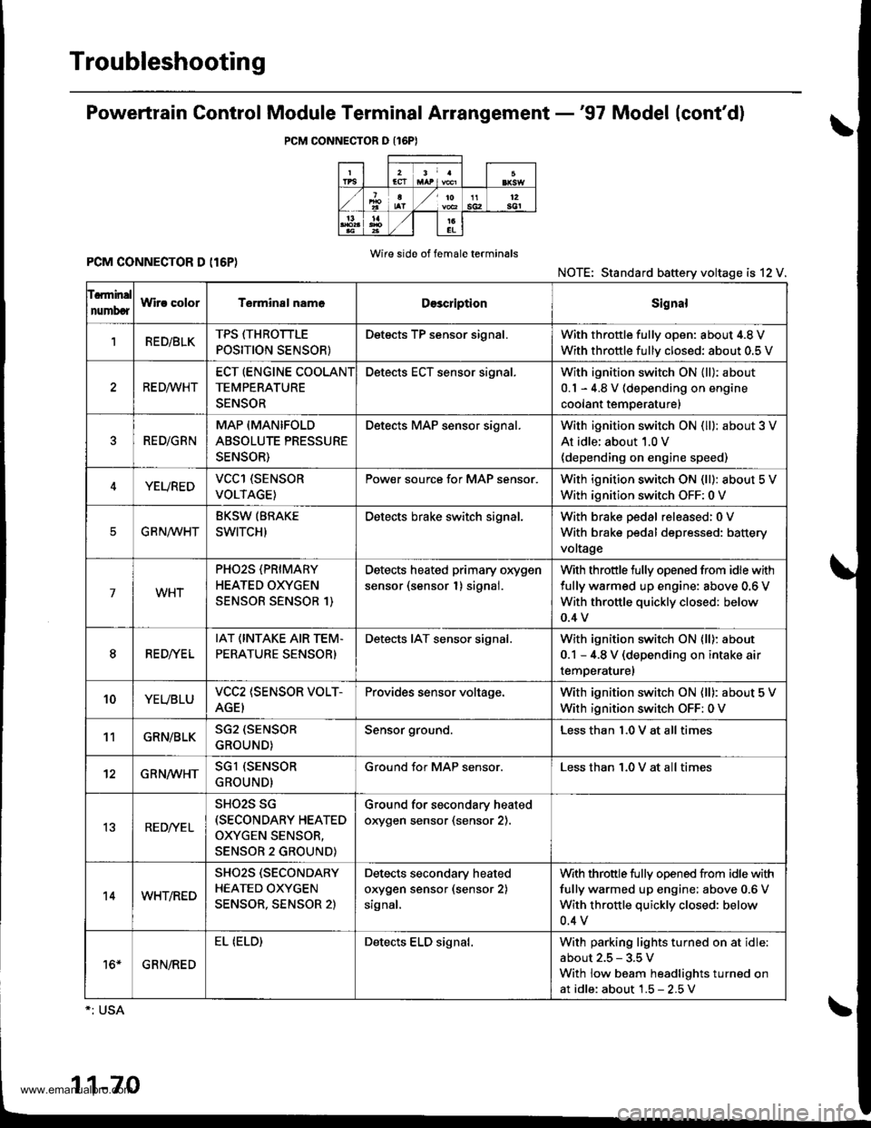
Troubleshooting
Powertrain Gontrol Module Terminal Arrangement -'97 Model (cont'd)
PCM CONNECTOR O {16PI
PCM CONNECTOR D (I6P)Wire side of f6male terminals
NOTE: Standard battery voltage is 12 V.
f.rminal
numbcrWir! colorT€rminal nam6DescriptionSignal
1RED/BLKTPS ffHROTTLE
POSITION SENSOR}
Detects TP sensor signal.With throttle fullv oDen: about 4.8 V
With throttle fullv closed: about 0.5 V
RE D,4/VHT
ECT (ENGINE COOLANT
TEMPERATURE
SENSOR
Detects ECT sensor signal.With ignition switch ON {ll): about
0.1 - 4.8 V (depending on engine
coolant temperature)
RED/GRN
MAP (MANIFOLD
ABSOLUTE PRESSURE
SENSOR)
Detects MAP sensor signal.With ignition switch ON (ll): about 3 V
At idle; about 1.0 V(depending on engine speed)
YEUREDVCCl (SENSOR
VOLTAGE)
Pow€r source for MAP sensor.With ignition switch ON (ll): about 5 V
With ignition switch OFF: 0 V
EG R N/WHT
BKSW (BRAKE
SWITCH)
Detects brake switch signal.With brake pedal released:0 V
With brake pedal depressed: battery
voltage
7WHT
PHO2S (PRIMARY
HEATED OXYGEN
SENSOR SENSOR 1)
Detects heated primary oxygen
sensor (sensor 1) signal.
With throttle fully opened from idle with
fully warmed up engine: above 0.6 V
With throttle quickly closed: below
0.4 v
8RED//E L
IAT (INTAKE AIR TEM.
PERATURE SENSOR)
Detects IAT sensor signal.With ignition switch ON lll): about
0.1 - 4.8 V (depending on intake air
temperaturel
10YEUBLUVCC2 (SENSOR VOLT-
AGEI
Provides sensor voltage.With ignition switch ON (ll): about 5 V
With ignition switch OFF: 0 V
11GRN/BLKSG2 (SENSOR
GROUND)
Sensor ground.Less than 1.0 V at all times
12GRN/WHTSGl (SENSOR
GROUND)
Ground for MAP sensor.Less than 1.0 V at all times
13RED/YE L
SHO2S SG(SECONDARY HEATED
OXYGEN SENSOR,
SENSOR 2 GROUND)
Ground for secondary heated
orygen sensor (sensor 2).
14WHT/RED
SHO2S (SECONDARY
HEATED OXYGEN
SENSOR, SENSOR 2)
Detects secondary heated
orygen sensor (sensor 2)
signal,
With throttle fully opened from idle with
fully warmed up engine; above 0.6 V
With throttle quickly closed: below
0.4 v
16*GRN/RED
EL (ELD)Detects ELD signal.With parking lights turned on at idle
about 2.5 - 3.5 V
With low beam headlights turned on
at idle: about 1.5 - 2.5V
1-70
www.emanualpro.com
Page 273 of 1395

Engine/Powertrain Control Module Terminal Arrangement - 38 - 00 Models
ECM/PCM CONNECTOR A (32P}
,/./5aIsca
,/ l,/t5ItsTs
n2ls!uCI
Wire side ot female terminalsECM/FCM CONNECTOR A {32P)NOTE: Standard baftery voltage is '12 V.
D93criptionSignal
3BLU2WBS {EVAP BYPASSSOLENOID VALVE)Drives EVAP bvoass solonoid valve.With ignirion switch ON {ll)r battery voltage
LT GRNMHTVSV {EVAP CONTROL CANISTEB VENT SHUT VALVE)D.ives EVAP controlcanisler vent shutWith ig^ition switch ON (ll): battery voltage
5',BLUCRS (CRUISE CONTROL SIG'NAL)Shift Oown signalinputfrcm cruise conWhen cruise control is used: pulses
6RED/YEL
PCS (EVAP PURGE CONTROLSOLENOID VALVE)Drives EVAP purge controlsolonoid valve.With engins running, engine coolant, below 154'F(68'C)r battery voltageWith engine running, engine coolant, above 154"F{6a'C}r duty conl.olled
8ELIOWHTSO2SHTC (SECONDARVHEATED OXYGEN SENSORHEATER CONTROL)
Drives sacondary heated oxygen sensorWith ignition switch ON (ll): banery voltageWith fully warmed up engine running: duty
10BRNSCS (SERVICE CHECX SIGNAL)Detects seNics check conneclor signal(he signalcausing a DTC indicatjon)with rhe lerminal connected:0 vWith the rerminaldisconnectedrabout 5 v or
l4'rGRN/8LKD4IND (D4INDICATOR)+3DIND (D INDICATORTIDrives D4*3. Dr'indicaior light.W,rh 04' , O" indrcator light turned O batter,
With D4*3, D*. indicator light turned OFFr0 V
16GRNI/ELFLR (FUEL PUMP RELAY)Drivss fusl pump relay.0 V for iwo seconds after ru'nin9 ign'lion swilchON lll), then banery voltage
17AL|(/REDACC (I/C CLUTCH RELAY}Drives l,/C clurch rclay.With compressor ONr0 VWith compressor OFF: battery voltage
18GRN/ORNMIL (MALFUNCTION INDICA.TOR LIGHT)Driv€s MlL.With MlLturned ON:0 VWith MIL turned OFF: battery voltage
19BLUNEP (ENGINE SPEED PULSE)Outputs engine spsed pulse.With sngine runnin9: pulses
20GRNFANC {RADIATOR FAN CONTROL)Drives r6diator fan rslay.With radaator fan running:0 VWith radaatorfan stopped: battery vollage
218LU/t/ELK-LINESends and receiv€s scan toolsignal.With ignition switch ON (ll): p'rlses
23WHT/REDSHO2S (SECONDARY HEATEDOXYGEN SENSOR. SENSOR 2iDetects secondary h€at€d oxygen sensorWith throttle fully opened from idle wilh fullywalmed up engine: above 0.6 Vwith rhrottle quickly closed: below 0-4 V
21BLU/WHTSTS (STARTER SWITCH SIG,NAL}Dotocts srarter switch signal.Whh staner switch ON (lll): batlery voltageWith srarter switch OFF: 0 V
26GBNPSPSW {P/S PsESSUFESWITCH SIGNAL)Detecrs PSP switch signal.At idle with steeing wh€el in stBighl ahead position: 0 VAt idls with nee ng wheel al full lockr banory voltage
2fBLU/BEOACS (Ir'C SWTCH SIGNAL}D€tects ly'C switch signal.With Ay'C switch ON:0 VWith l/C swil€h OFF: about 5 V
2A'\WHT/NEDSLU {INTERLOCK CONTROLUNIT)Orives interlock control unil.With ignilion switch ON (ll)and brake pedaldepressed: battery vohage
29LT GRNPTANK (FUEL TANK PRES'SURE SENSOR)Detocts fueltank pressure sensor signal.With agnition switch ON (ll) and fuel fill capopensd; about 2.5 v
GBN/FEDEL (ELD}Detects ELD signal.Wirh paaing rightstumed on at idle:about 2.5 - 3.5 VWith low beam headlights tumed on at idle:about 1.5-2.5V
GRN/WHTBKSW (BRAKE SWTTCH)Dst€cts brake switch signal.Wirh brake pedal released:0 VWith brake pedal depressed: battery vollage
13: '98 modsl
15: USA(cont'd)
11-71
www.emanualpro.com