Page 1070 of 1395
Fenderwell
Front Wheelwell Protector
Replacement
NOTE:
a Take care not to scratch the front wheelwell protector
and body.
. Use a T30 Torx bit to remove the Torx screw.
>: Screw locationsa >,3
/\l
6'thp IY/
>: Clip locations,
AI
4t I
wt I
al
B>, 1
,,-C\
s)Dv.l/
6x1.0mm9.8Nm(1.0kgf.m,7.2 tbf.ft)
NOTE: Before temoving thefront wheelwell Protector, remove
the screw from the front
bumper and lower the front
bumper.
Installation is the reverse of the removal Drocedure.
NOTE: lf necessary, replace any damaged clips.
Inner Fender Replacement
NOTE: Take care not to scratch the body.
Remove the front wheelwell protector,
>: Screw locations, 4
Installation is the reverse of the removal procedure.
NOTE; lf necessary, replace any damaged clips.
>: Clip locations,
ffi)fl(
l#:rl
A\
s))pp>Y]
INNER FENDER
20-89
www.emanualpro.com
Page 1071 of 1395
Fenderwell
Rear Wheelwell Protector
Replacement
NOTE:
. Take care not to scratch the rear wheelwell protector
and body.
. Use a T30 Torx bit to remove the Torx screw.
>: Screw locationsa>,3
I
6him" lY/
>: Clip locationsA >,5 B>, 1
B>, I
,.{\
F ),@Y-./
6x1.0mm9.8 N.m {1.0 kgl.m.7.2 rbtft)
YnTn | |
/'d)Ul | +['Tl+l
\=lHl | _H_l
tlrflJ | - INoTE: Before removinsthe- | lclip. remove the screw
lnstallation is the reverse of the removal procedure.
NOTE: lf necessary, replace any damaged clips.
from the rear bumper andlower the rear bumper,
20-90
Fuel Pipe Protector Replacement
NOTE: Take care not to scratch the body.
Remove the rear wheel (see section 18).
>: Clip locations,3
/ll
qK
1l
lnstallation is the reverse of the removal Drocedure.
NOTE: lf necessary. replace any damaged clips.
www.emanualpro.com
Page 1074 of 1395
Hood Opener Cable Replacement
NOTE:
. When removing the clips, use a clip remover.
. Take care not to bend the opener cable.
Remove:
. Front wheelwell protector and inner fender {left side, see page 20 89}
. Front grille (see page 20-77)
. Kick panel (left side. see page 20-411
HOOD LATCH(see page 20-95)
Route the openercable through thehole in the body.
>: Clip locations,3
'.--)r I
@l
Installation is the reverse of the removal procedure.
NOTE:
. lf necessary. replace any damaged clips.
. Make sure the hood opener cable is routed and connected properly.
. Make sure the hood opens properly.
t"
HOOD RELEASEHANDLE(see page 20 95)
www.emanualpro.com
Page 1080 of 1395

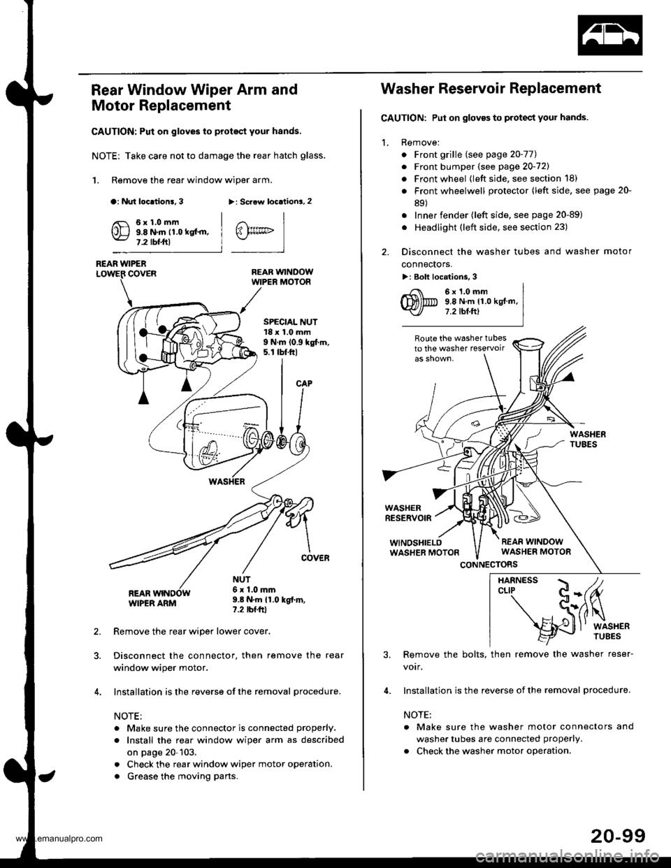
Rear Window Wiper Arm and
Motor Replacement
CAUTION: Put on gloves to protect your hands.
NOTE; Take care not to damage the rear hatch glass.
1. Remove the rear window wiper arm.
a: Nut loc.tion!, 3>: Scaow locationa, 2
REAR WINDOWWIPER MOIOR
REAR WIPERCOVER
REARWIPER ARM
6x1.0mm9.8 N.m 11.0 kgt'm,7.2 tbf.ftl
SPECIAL NUT18 x 1.0 mm9 N.m 10.9 kgt m,5. r tbt.ftl
NUT6x 1.0mm9.8 N.m {1.0 kgt.m,?.2 tbfftl
Remove the rear wiper lower cover.
Disconnect the connector, then remove the rear
window wiper motor.
Installation is the reverse of the removal procedure.
NOTE:
. Make sure the connector is connected properly.
. Install the rea. window wiper arm as described
on page 20-103.
. Check the rear window wiper motor operation.
. Grease the moving parts.
@rrc
Washer Reservoir Replacement
GAUTION: Put on gloves to protect your hands.
1. Remove:
. Front grille (see page 20-771
. Front bumper (see page 20-721
. Front wheel {left side, see section 18)
. Front wheelwell protector (left side, see page 20-
89)
. Inner fender (left side, see page 20-89)
. Headlight (left side, see section 23)
2. Disconnect the washer tubes and washer motor
connectors.
>: Bolt locations, 3
6x1.0mm9,8 N.m 11.0 kgt.m,7.2 tbt.ftl
Route the washer tubesto the washer teservoir
WASHERRESERVOIR
WINOSHIELOWASHER MOTON
CONNECTORS
3. Remove the bolts, then remove the washer reser-
votr,
4. Installation is the reverse of the removal procedure.
NOTE:
a Make sure the washer motor connectors and
washer tubes are connected properly.
. Check the washer motor operation.
HARNESS / tcLrP C-(fu
- S(ilq
s{J
l' wrsHER
20-99
www.emanualpro.com
Page 1081 of 1395
Wiper/Washer
Windshield Washer Tube Replacement
NOTE:
. Take care not to scratch the related parts and body.. When removing the clips, use a clip remover.
Remove the following parts.
. Left front wheelwell protector (see page 20-89). Left inner fender (see page 20-89)
WINDSHIELOWASHER NOZZLES Y-JOINT
Boute the w6sher tubesto the washer reservoir
'97 model:
63'fr{-------
ax---\J
,.&--
\7>: Clip locationsA >,2 B >,1c>, 1D>,1
\
lnstallation is the reverse of the removal procedure.
NOTE:
. Take care not to pinch the washer tubes.
. lf necessary, replace any damaged clips.. After installing, adjust the aim ofthe washer nozzles (see page 20-103).
20-100
www.emanualpro.com
Page 1241 of 1395

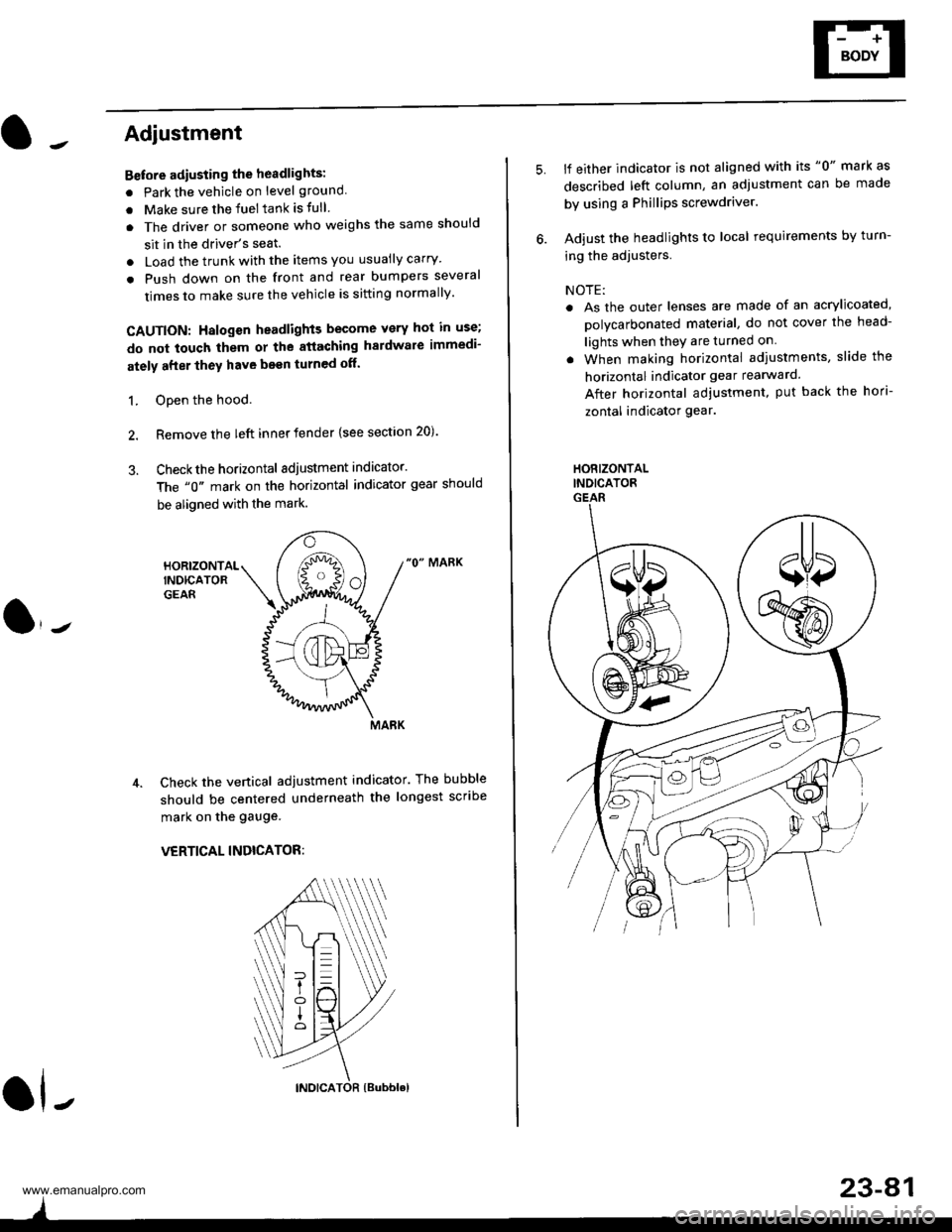
Adjustment
Bstore adiusting the headlights:
. Park the vehicle on level ground
. Make sure the fuel tank is tull
. The driver or someone who weighs the same should
sit in the driver's seat.
. Load the trunk with the items you usually carry'
. Push down on the front and rear bumpers several
times to make sure the vehicle is sitting normally'
CAUTION: Halogen headlights become very hot in use;
do not touch them or the atiaching hardware immedi-
ately after they have been turned off.
1. ODen the hood.
2. Remove the left inner fender {see section 20).
3. Checkthe horizontal adjustment indicator.
The "0" mark on the horizontal indicator gear should
be aligned with the mark.
"0" MARK
Check the vertical adjustment indicator. The bubble
should be centered underneath the longest scribe
mark on the gauge.
VERTICAL INDICATOR:
ol-
)
5.lf either indicator is not aligned with its "0" mark as
described left column, an adjustment can be made
by using a Phillips screwdriver.
Adjust the headlights to local requirements by turn-
ing the adjusters.
NOTE:
. As the outer lenses are made of an acrylicoated,
polycarbonated material, do not cover the head-
lights when they are turned on
. When making horizontal adiustments, slide the
horizontal indicator gear rearward.
After horizontal adjustment, put back the hori-
zontal indicator gear.
HORIZONTALINDICATORGEAR
23-A1
www.emanualpro.com