Page 202 of 1395

Fan Control
Fan Motor Testing
1. Disconnect the 2P connector.
Terminalside ofmale terminals
Test the motor by connecting battery power to theNo. 2 terminal and ground to the No. 1 terminal.
lf the motor fails to run or does not run smoothly,reptace rt.
RADIATOR FAN MOTOR
10-14
Radiator Fan Switch Testing
E@ Removing the radiator fan switch whilethe engine is hot can cause the coolant to spray out, seri-ously scalding you. Always let the enginc and radiatorcool down before removing the radiator fan switch.
1. Remove the radiator fan switch from the thermostathousing (see page 10 '10).
2. Suspend the radiator fan switch in a container ofwater as shown.
Heat the water, and check the temperature with athermometer. Do not let the thermometer touch thebottom of the hot container.
Measure the continuity between the A and B termi-nals according to the table.
Bleed the air from the cooling system after installingthe radiator fan switch (see page 10-5).
Terminal
op".*i- Tr"ip".a*" \.B
SWITCH
ON196 - 203"F
{91 - 95.C)o---o
OFF
5 - 14"F (3 - 8.C)
lower than the tem-peratu re wh en itgoes on
www.emanualpro.com
Page 203 of 1395
Goolant Temperature Gauge
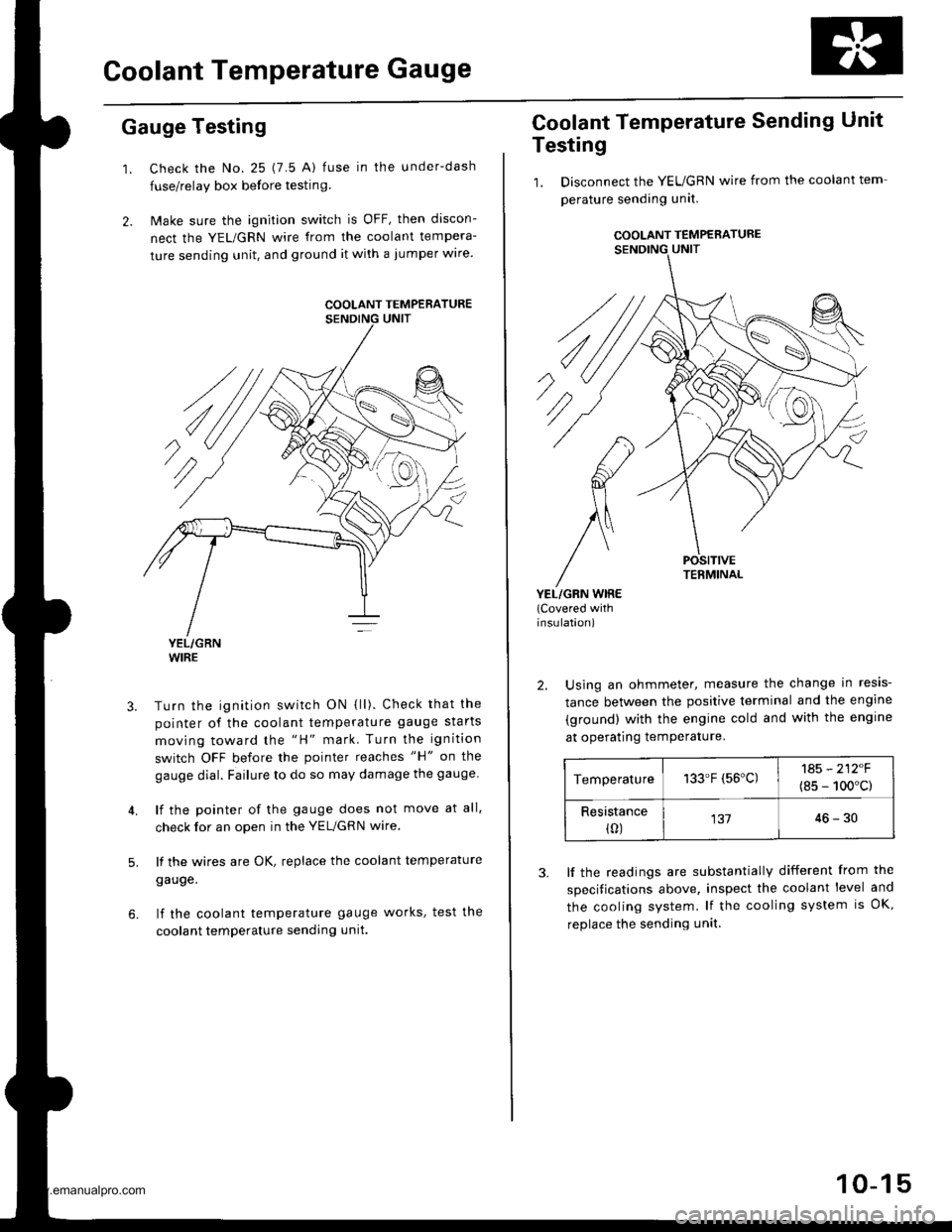
Gauge Testing
1. Check the No. 25 (7.5 A) fuse in the under-dash
fuse/relay box before testin9.
2. Make sure the ignition switch is OFF, then discon-
nect the YEL/GRN wire from the coolant tempera-
ture sending unit. and ground it with a jumper wire.
YEL/GRNWIRE
Turn the ignition switch ON {ll). Check that the
pointer of the coolant temperature gauge starts
moving toward the "H" mark. Turn the ignition
switch OFF before the pointer reaches "H" on the
gauge dial. Failure to do so may damage the gauge.
lf the pointer of the gauge does not move at all,
check for an open in the YEL/GRN wire.
lf the wires are OK, replace the coolant temperature
gauge.
lf the coolant temperature gauge works, test the
coolant temperature sending unit.
5.
COOLANT TEMPERATURE
Coolant Temperature Sending Unit
Testing
1. Disconnect the YEUGRN wire from the coolant tem
perature sending unit.
COOLANT TEMPERATURE
POSITIVETERMINAL
YEL/GRN WIRE(Covered withinsulation)
2. Using an ohmmeter, measure the change in resis-
tance between the positive terminal and the engine
(ground) with the engine cold and with the engine
at operating temPerature.
Temperature133.F (56'C)1A5 - 212F
(8s - 100'c)
Resistance(0)13746-30
3. lf the readings are substantially different from the
specitications above, inspect the coolant level and
the cooling system. lf the cooling system is OK,
replace the sending unit.
10-15
www.emanualpro.com
Page 208 of 1395
DATA LINK CONNECTOR {DLC) I16P}Troubleshooting Procedures, page 1 1'60PRIMARY HEATED OXYGEN SENSOR
{PRIMARY HO2SI {SENSOR 1)Troubleshooling, page 11 110
SECONDARY HEATED OXYGENSENSOR{SECONDARY HO2S) {SENSOR 2)Troubleshooting, page 1 1-1 17
'97 - 98 models:
AIR CLEANERReplacement, page 1 1'194
Troubleshooting, page 1 'l -200
THROTTLE BODY (TB)Inspection, page 11 196Removal, page 11-197Disassembly, page 1 1-'198
POWERTRAIN CONTROL MODULE(PCM) (A/TI
Troubleshooting Procedures, page 1 1-60Troubleshooting. page 1 1'82
THROTTLE CABLEInspection/Adjustment, page 1 1-1 94Installation, page 11- 195
VENTILATION (PCV) VALVEInspection, page 1 1-201FAST IDLEVALVE (A/T}
(cont'd)
1 1-5
PGM-FIMAIN RELAYRelay Testing, page 11-l87Troubleshooting. page 1'1 188
SERVICE CHECK CONNECTOR {2PITroubleshooting Procedures, page 1 1-60
,a'=_-_
WAY CATALYTIC
Inspection, page 1 1-168
www.emanualpro.com
Page 210 of 1395
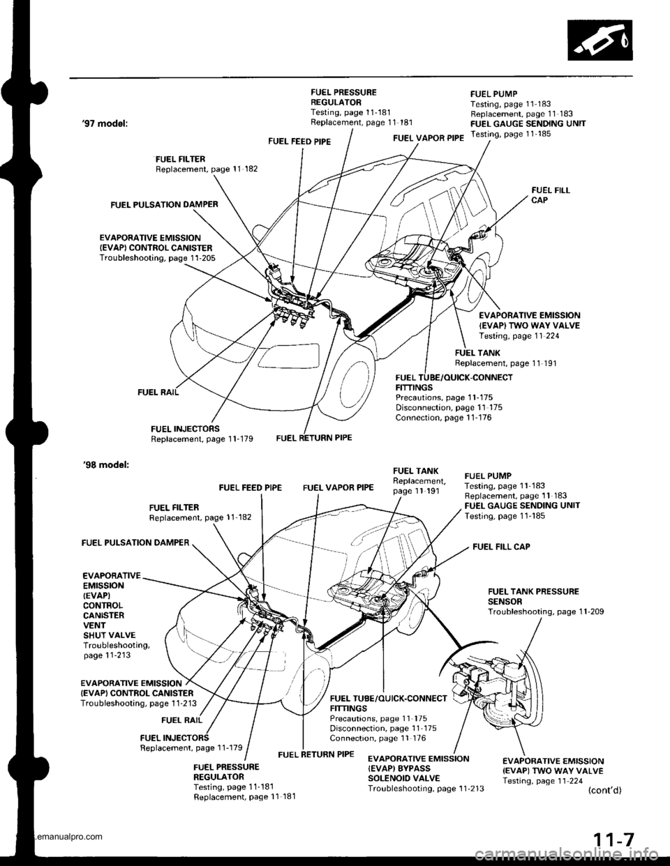
FUEL PRESSUREREGULATORTesting, page 11-181Replacement, page 11 181
FUEL PUMPTesting, page 11 183Replacement, page 11 183FUEL GAUGE SENDING UNITTesting, page 11 185
'97 model:
'98 model:
FUEL PULSATION DAMPER
EVAPORATIVE EMISSIONIEVAP) CONTROL CANISTERTroubleshooting. page 1'l-205
FUEL FILTERReplacement, page 11 182
FUEL INJECTORSReplacement, page 1 1-179
FUEL FEED PIPEFUEL VAPOR PIPE
FUELFITTINGS
FUEL FILLCAP
EVAPORATIVE EMISSION
IEVAPI TWO WAY VALVETesting, page 11 224
TANKReplacement, page 11 191
-CONNECT
Precautions, page 1 1-175Disconnection, page 11 175Connection, page 1 1-176
FUEL FILTERReplacement, page 11 182
FUEL FEED PIPEFUEL VAPOR PIPE
FUEI- TANKReplacement,page 1l 191
FUEL TUBE/OUICK.CONNECTFITTINGSPrecautions, page 11 '175
Disconnection, page 11 175Connection, page 11 176
FUEL PUMPTesting, page 11 183Replacement, page 11 183FUEL GAUGE SENDING UNITTesting, page 1l'185
FUEL FILL CAP
FUEL TANK PRESSURESENSORTroubleshooting, page 1 l-209
FUEL PULSATION DAMPER
EVAPORATIVEEMTSSTONIEVAPICONTROLCANISTERVENTSHUT VALVETroubleshooting,page 11'213
EVAPORATIVE EMISSIONIEVAPI CONTROL CANISTERTroubieshooting, page 1 1 -213
FUEL RAIL
FUELFeplacement, page 1 1-179
FUEL PRESSURENEGULATORTesting, page 11-181Replacement, Page 11 181
EVAPORATIVE EMISSION{EVAP) EYPASSSOLENOID VALVETroubleshooting, page 1 1'213
€VAPORATIVE EMISSION{EVAP) TWO WAY VALVETesting, page 11 224(cont'd)
www.emanualpro.com
Page 211 of 1395
Gomponent Locations
Index lcont'd)
'99 - (X) modols:
FUEL TANKReplacement,page 11-191
FUEL FEED PIPE
FUEL FILTERReplacement, page 11 182
FUEL VAPOR PIPE
FUELFITTINGS
FUEL PUMPTesting, page '11 183Replacement, page 1 1_183FUEL GAUGE SENDING UNITTesting, page 11-185
FUEL FILL CAP
EVAPORATIVE EMISSIONIEVAP) CONTROLTroubleshooting, page 1 1-213
FUEL PULSATION DAMPER
FUEL RAIL
FUELReplacement, page 1 1-179
EVAPORATIVEEMtSStON
IEVAP)CONTROLCANISTERVENTSHUT VALVETroubleshooting,page 11-213FUEL TANK PRESSURESENSORTroubleshooting, page 1'l'208
EVAPORATIVE EMISSION{EVAP) TWO WAY VALVETesting, page 11-224
FUEL PRESSUREREGULATORTesting, page 11-181Replacement, page 11 181,CONNECT
PrecaLrtions, page 1 1-175Disconnection, page 1 1-175Connection, page 176
EVAPORATIVE EMISSION{EVAPI BYPASSSOLENOID VALVETroubleshooting, page 11 213
www.emanualpro.com
Page 385 of 1395
Fuel Pump
Testing
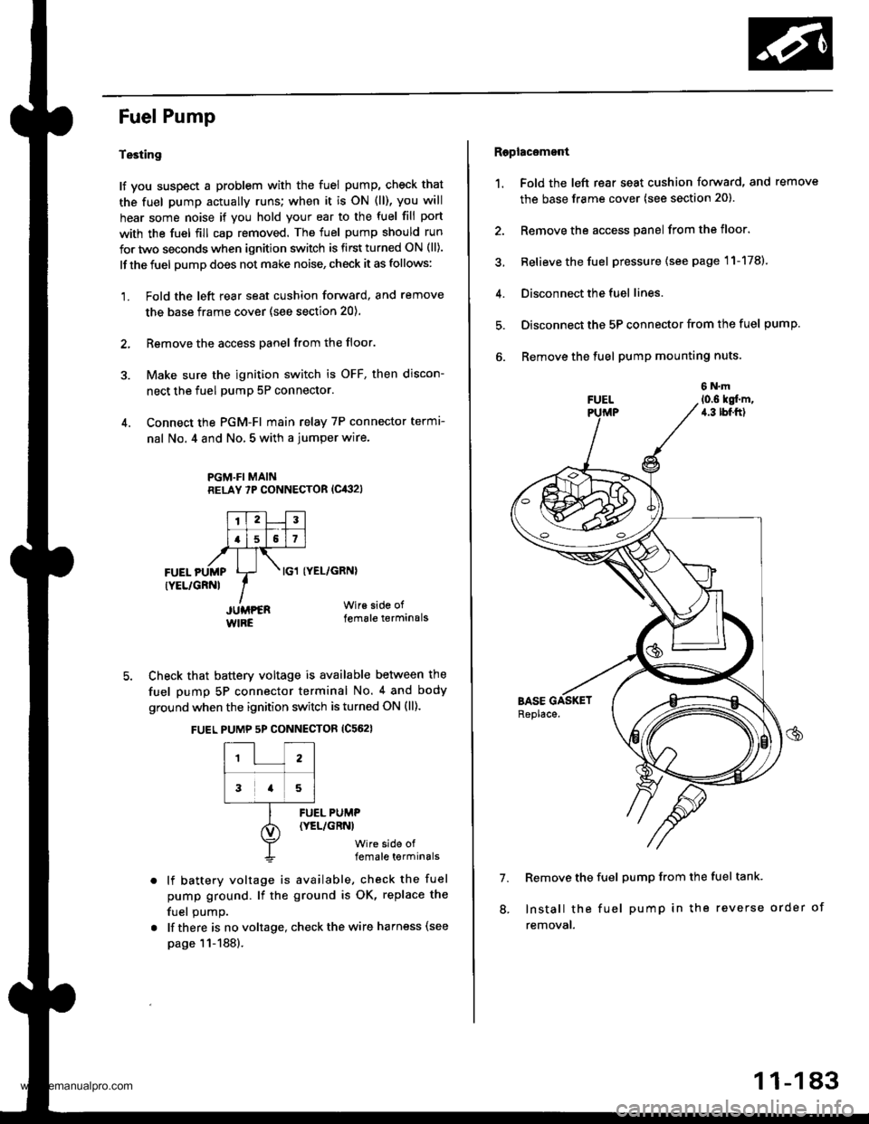
lf you suspect a problem with the fuel pump, check that
the fuel pump actually runs; when it is oN (ll), you will
hear some noise if you hold your ear to the fuel fill port
with the fuel fill cap removed. The fuel pump should run
for two seconds when ignition switch is first turned ON (ll).
lf the fuel pump does not make noise, check it as follows:
1. Fold the left rear seat cushion forward, and remove
the base frame cover (see section 20).
2, Remove the access panel from the floor.
3. Make sure the ignition switch is OFF, then discon-
nect the fuel pumP 5P connector.
4. Connect the PGM-FI main relay 7P connector termr-
nal No. 4 and No, 5 with a jumper wire.
PGM.FI MAINRELAY 7P CONNECTOR (Cit:}2l
I'TtlJilt f -r'-r ll.l5l517l,frTt-,at\FUEL pUMp Lr- . tcl tyEL/cRNl
rYEL/cRNl IIJUMPER Wir€ side of
WIRE female terminals
5. Check that battery voltage is available between the
fuel pump 5P connector terminal No. 4 and body
ground when the ignition switch is turned ON (ll).
FUEL PUMP 5P CONNECTOR {C562}
12
3a5
lf battery voltage is available, check the fuel
pump ground. lf the ground is OK, replace the
fuel oumo.
lf there is no voltage, check the wire harness (see
page 11-188).
FUEL PUMP(YEL/GRNI
wire side offemale terminals
Raplac6mont
1. Fold the left rear seat cushion forward, and remove
the base frame cover (see section 20).
2. Remove the access panel from the floor.
3, Relieve the fuel pressure (see page 11-178).
4. Disconnect the fuel lines.
5. Disconnect the 5P connector from the fuel pump.
6. Remove the fuel pump mounting nuts.
7. Remove the fuel pump from the fuel tank.
Install the fuel pump in the reverse order of
removal.
8.
11-183
www.emanualpro.com
Page 386 of 1395
Fuel Supply System
Fuel Gauge
Tssting
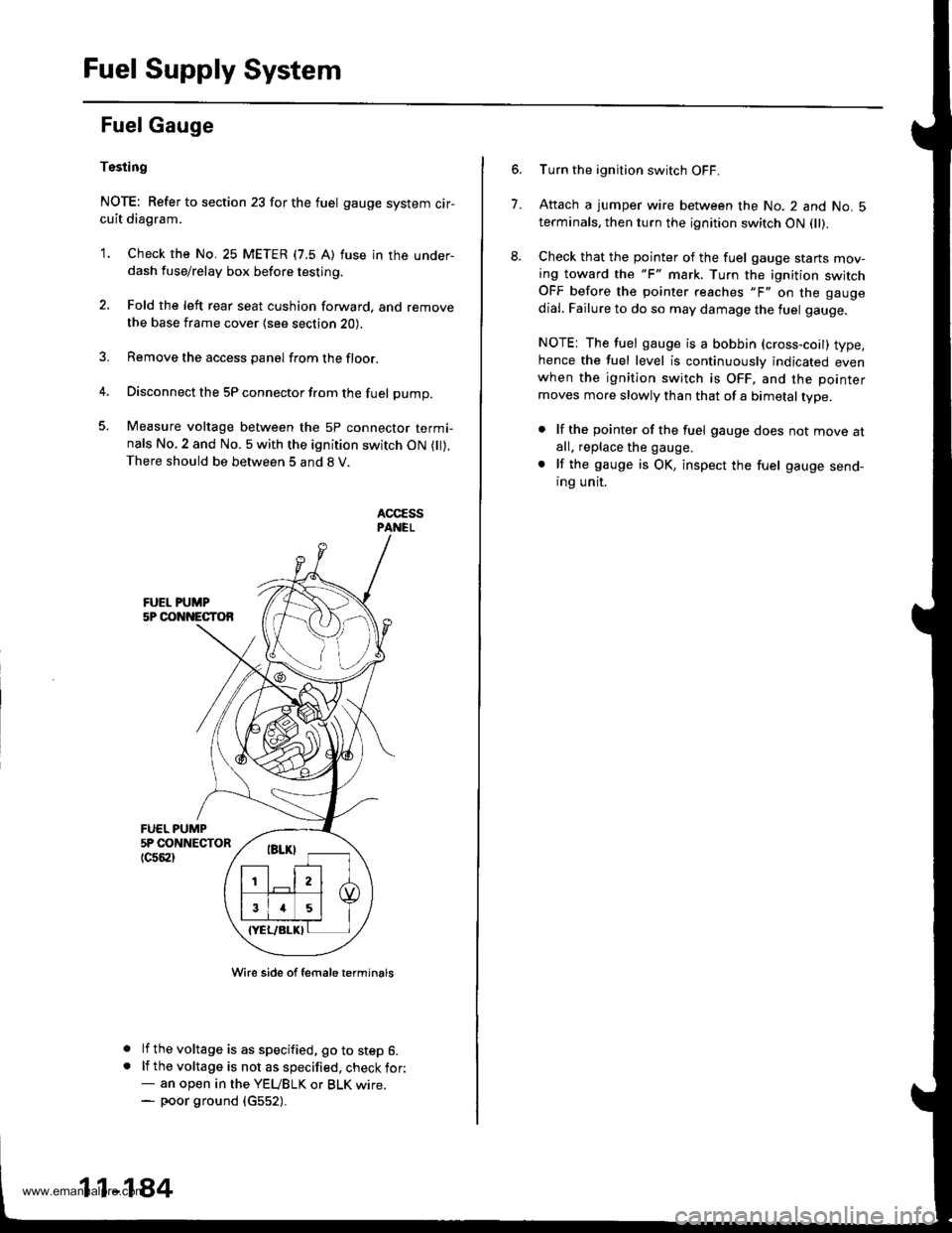
NOTE: Refer to section 23 for the fuel gauge system cir-cuit diagram.
'1. Check the No. 25 METER (7.5 A) fuse in the under-dash fuse/relay box before testing.
2. Fold the left rear seat cushion forward, and remove
the base frame cover {see section 20).
3. Remove the access panel from the floor.
4. Disconnect the 5P connector from the fuel pump.
5. Measure voltage between the 5P connector termi-nals No.2 and No. 5 with the ignition switch ON ( ).There should be between 5 and 8 V.
FUEL PUMP5P CONNECTOR
tc56al
a
a
Wire side of female t€rminals
lf the voltage is as specified, go to step 6.lf the voltage is not as specified, check for:- an open in the YEUBLK or BLK wrre.- poor ground (c552).
11-184
7.
Turn the ignition switch OFF.
Attach a jumper wire between the No. 2 and No. 5terminals, then turn the ignition switch ON fll).
Check that the pointer of the fuel gauge starts mov-ing toward the "F" mark. Turn the ignition switchOFF before the pointer reaches "F" on the gauge
dial. Failure to do so may damage the luel gauge.
NOTE: The fuel gauge is a bobbin (cross-coil) type,hence the fuel level is continuously indicated evenwhen the ignition switch is OFF, and the pointer
moves more slowly than that of a bimetal type.
. lf the pointer of the fuel gauge does not move atall. replace the gauge.
. lf the gauge is OK, inspect the fuel gauge send-ing unit.
www.emanualpro.com
Page 388 of 1395
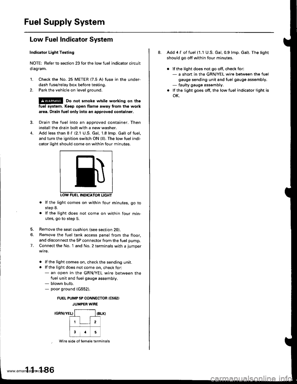
Fuel Supply System
Low Fuel Indicator System
Indicator Light Testing
NOTE: Refer to section 23forthe lowfuel lndicator circuit
clragram.
1. Check the No. 25 METER (7.5 A) fuse in the under-
dash fuse/relay box before testing.
2. Park the vehicle on level ground.
@ Do not smoke while working on the
fuel system. Keep open flame away trom the work
aroa. Drain fuel only into an approved container.
Drain the fuel into an aoDroved container. Then
install the drain bolt with a new washer.
Add less than 8 f (2.1 U.S. Gal. 1.8 lmp. Gal) of fuel,
and turn the ignition switch ON {ll). The low fuel indi-
cator light should come on within four minutes.
INDICATON LIGHT
. lf the light comes on within four minutes, go tostep 8.
. lf the light does not come on within four min-
utes. go to step 5.
Remove the seat cushion (see section 20).
Remove the fuel tank access panel from the floor,
and disconnect the 5P connector from the fuel pump,
Connect the No. 1 and No. 2 terminals with a jumper
wire.
. lf the lightcomeson, checkthe sending unit.. lf the light does not come on, check for:- an open in the GRN/yEL wire between thefuel unit and fuel gauge assembly.- blown bulb.- poor ground (G552).
FUEI- PUMP 5P CONNECTOR (C562)
JUMPER WIRE
IGRN/YEL}
7.
1 1-1 86
Wire sid€ ol tem€le terminals
8. Add 4 / of fuel (1.1 U.S. Gal, 0.9 lmp. Gal). The light
should go off within four minutes.
. lJ the light does not go off, check for:- a short in the GRNA/EL wire between the fuel
gauge sending unit and fuel gauge assembly.- faulty gauge assembly.
. lf the light goes off, the low fuel indicator light is
oK.
www.emanualpro.com