Page 37 of 1395

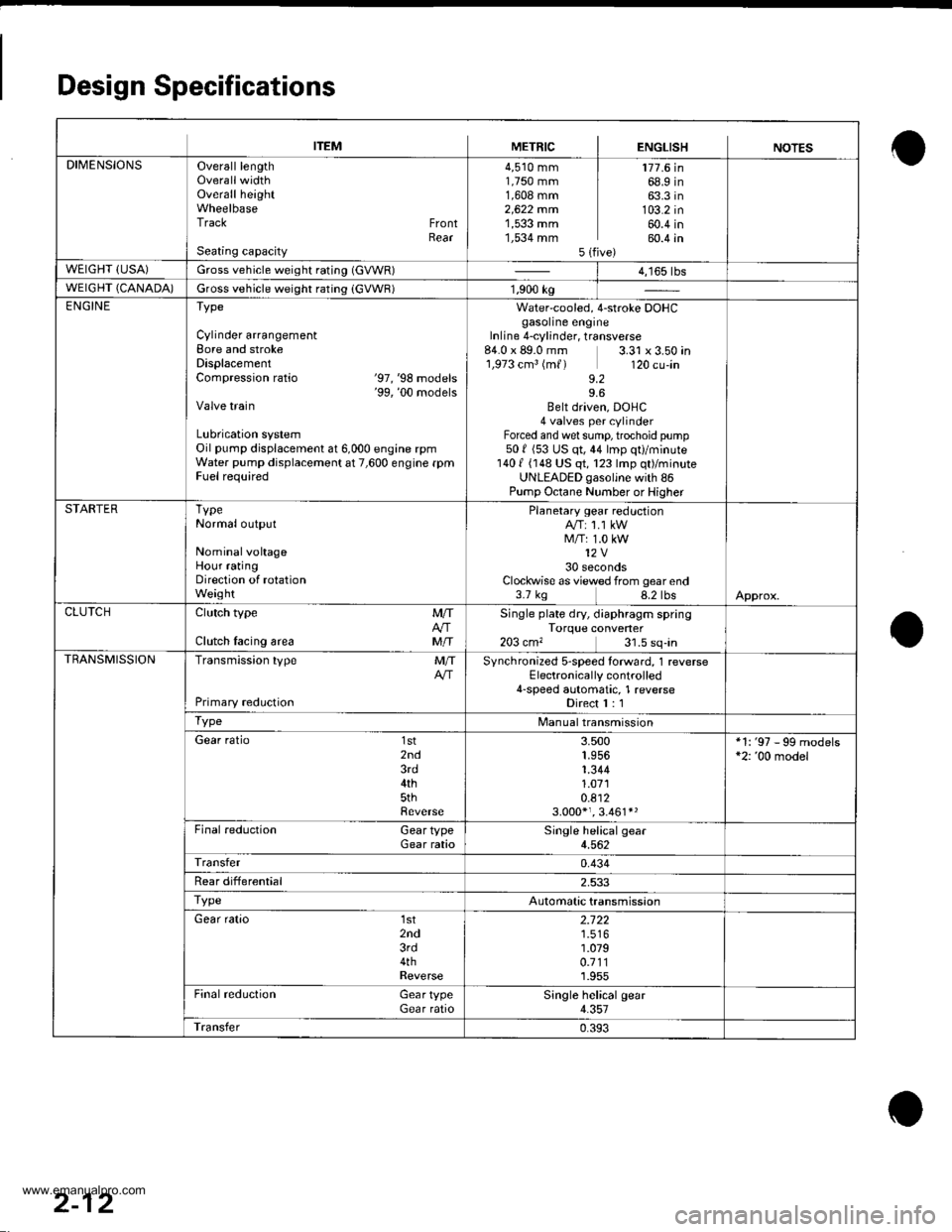
Design Specifications
ITEMMETRICENGLISHNOTES
DIMENSIONSOverall lengthOverallwidthOverall heightWheelbaseTrack FrontRearSeating capacity
4,510 mm1,750 mm1,608 mm2,622 mrn1,533 mm1,534 mm5lf
177.6 in68.9 in63.3 in103.2 in60.4 in60.4 in
WEIGHT (USA)Gross vehicle weight rating (GVWR)| 4,165 tbs
WEIGHT (CANADA)Gross vehicle weight rating (GVWR)1,900 kg
ENGINEType
Cylinder arrangementBore and strokeDisplacementCompression ratio '97,'98 mooers'99, '00 modelsValve train
Lubrication systemOil pump displacement at 6,000 engine rpmWater pump displacement at 7,600 engine rpmFuel required
Water-cooled, 4-stroke DOHCgasoline engineInline 4-cylinder, transverse84.0 x 89.0 mm.1,973 cm3 (m{)
9.2
3.31 x 3.50 in120 cu-in
9.6Belt driven, DOHC4 valves per cylinderForced and wet sump, trochoid pump501 (53 US qt,44 lmp qt)/minute1401 (148 US qt, 123 lmp qt)/minuteUNLEADED gasoljne with 86Pump Octane Number or Higher
STARTERTypeNormal output
NominalvohageHour ratingDirection of rotationWeight
Planetary gear reductionA/T: 1.1 kWM/T: 1.0 kW12V30 secondsClockwise as viewed from gear end3.7 kg 8.2 lbsApprox.
CLUTCHClutch type
Clutch lacing area
MIT
MIT
Single plate dry, diaphragm springTorque converter203 cm, 31.5 sq-in
TRANSMISSIONTransmission type
Primary redLrction
MITSynchronized s-speed torward, 1 reverseElectronically controlled4-speed automatic, 1 reverseDirect I : 1
TypeManualtransmission
Gear ratio 1st2nd3rd4th5thReverse
3.5001.9561.3441.0710.8123.000*,. 3.461*'
*1: '97 - 99 models*2: '00 model
Final reduction Gear typeGear rataoSingle helical gear4.562
Transfer0.434
Rear differential2.533
TypeAutomatic transmission
Gear ratio 1st2nd3rd4thReverse
2.722
1.0790.7111.955
Final reduction Gear typeGear ratioSingle helical gear4.357
Transfer0.393
2-12
www.emanualpro.com
Page 38 of 1395

--
-
METRICITEMENGLISHNOTES
AIR CONDITIONINGCooling capacity3,520 Kcal/h j 14,000 BTU/h
Compressor Type/manutacturerNo. of cylinderCaPacityMax. speedLubricant capacityLubricant type
Scroll/KElHlN
85.7 mf/rev | 5.23 cu'in/rev10,000 rpm130mf 1 algIlozsP-10
Condenser TypeCorrugated fin
Evaporator TypeCorrugated fin
Blower TypeMotor inputSpeed controlMax. capacity
Sirocco fan200 w 112 v4-Speeo440 m3/h 15,500 cu fvh
Temperature control
Compressor clutch TypePower consumptionDry, single plate, poly-V-belt drive40 W max./12 VAt 68'F (20 C)
Befrigerant TypeOuantity
HFC-134a 1R-134a)zoo o' g 24j an oz
STEERING SYSTEMTypeOverall ratioTurns, lock to lockSteering wheel diameter
Power assisted, rack and pinion
SUSPENSIONType Front
Bear
Shock absorber Front and Rear
Independent double wishbone, coil springwith stabilizerIndependent double wishbone, coil springwith stabilizerTelescopic, hydraulic nitrogen gas tilled
WHEEL ALIGNMENTCamber
CasterTotaltoe
FronthearFrontFrontRear0inln 1/16 in0mmln2mm
0'- r"00'2.10'�
BRAKE SYSTEMTvpe
Pad surface areaLining surface areaParking brake
Front
RearFrontRearTvpe
Power-assisted selt-ad,ustingventilated discPower assisted self-adiusting drum49 cm, x 2 7.6 sq-in x 273 cm, x2 11.3 sq-in x 2Mechanical actuating, rear two wheel brakes
Drum brake
TIRESize and pressureSee tire inlormation label.
ELECTRICALBafteryStarterAlternator
In under-dash fuse/relay boxIn under hood fuse/relay box
In underhood ABS fuse/relay boxHeadlightsFront turn signal lights
Front parking lightsFront side marker lightsRear side marker lightsRear turn signal lightsErake/parking lightsBack-up lightsCeiling lights {fronvrear)License plate lightSpotlightsHigh mount brake lightlgnition key lightAshtray lightGauge lightsIndicator lightslllLrmination and pilot IightsHeater illumination lights
12 V, 36 AH/s HR12V 1.0, 1.1 kW12V 100A
7.5 A, 10 A, 15 A, 20 A7.5 A, 10 A, 15 A, 20 A, 30 A, 40 A'100 A7.5 4,20 A. 40 A12V 60/55 W12 V- 21 W ('97 model),12 V - 27 W ('98-00 models)12V 5 W {'97 model),3 CP ('98 - 00 models)12V-8W12 V,3 CP12V-21W12 V 2115 W12V 21 CP (18 W)12V-8W12V-8W12V-5W12V -21W
12 V- 1.4 W12V 1.4 W12 V 1.4 W,3 W,3.4 W12V-0.84W, 1.12 W, 1.4 W,3 W, LED12 V - 0.84 W, 1.4 W, LED12 V,1.4 W
2-13
www.emanualpro.com
Page 69 of 1395

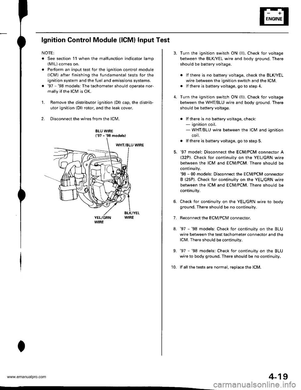
lgnition Control Module (lCMl Input Test
NOTE:
. See section 11 when the malfunction indicator lamp(MlL) comes on.
. Perform an input test for the ignition control module(lCM) after finishing the fundamental tests for the
ignition system and the fuel and emissions systems.
. '97 -'98 models: The tachometer should operate nor-
mally if the ICM is OK.
L Remove the distributor ignition (Dl) cap, the distrib-
utor ignition (Dl) rotor, and the leak cover.
2. Disconnect the wires from the lCM.
8LU WIRE{'97 - '98 models}
4-19
7.
Turn the ignition switch ON {ll). Check for voltage
between the BLK,^/EL wire and body ground. There
should be battery voltage.
. lf there is no battery voltage, check the BLK/rEL
wire betlveen the ignition switch and the lclvl.
. lf there is baftery voltage, go to step 4.
Turn the ignition switch ON (ll). Check for voltage
between the WHT/BLU wire and body ground. There
should be battery voltage.
. lf there is no batteryvoltage, check:- ignition coil.- WHT/BLU wire between the ICM and ignition
corl.
. lf there is battery voltage, go to step 5,
'97 model: Disconnect the ECM/PCM connector A(32P). Check for continuity on the YEL/GRN wire
between the ICM and ECM/PCM. There should be
continuity.'98 - 00 models: Disconnect the ECM,PCM connector
B (25P). Check for continuity on the YEUGRN wire
between the ICM and ECM/PCM. There should be
continuity.
Check for continuity on the YEUGRN wire to body
ground. There should be no continuity.
Reconnect the ECM/PClvl connector.
'97 -'98 models: Check for continuity on the BLU
wire between the test tachometer connector and the
lCM. There should be continuity.
'97 -'98 models: Check for continuity on the BLU
wire to body ground. There should be no continuity.
lf all the tests are normal, replace the lCM.
9.
'10.
www.emanualpro.com
Page 87 of 1395
UNDER.OASH FUSARELAY BOX
INDICATORLIGHT(0.84W)
lPIOSET
526712813
CRUISE CONTROT UNLT 10
11114
COMEINATONL GH'I SWITCH
f7
IRED/BLK
Gircuit Diagram
*: '98 00 models withAutomatic Transmission.
J
BRAK€LGHTSPNK BLK BLK
I L_l
tl
4F /lr,mcern I I
Y{"^ i?tr'.flffi'JF ) l
I
t loN : Pedar rereasedl /l
8LK BLK
TI
G101 G401
CRUISECONTROLACTUATOR
t'BLK
n:
G202
IGNIT ONSWITCHUNDER.HOOD FUSEi RELAY BOX
No 41 (100A) No 42 (404)
4-37
www.emanualpro.com
Page 164 of 1395

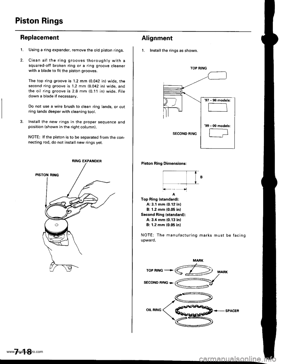
Piston Rings
2.
Replacement
1.Using a ring expander, remove the old piston rings.
Clean all the ring grooves thoroughly with a
squared-off broken ring or a ring gtoove cleaner
with a blade to fit the piston grooves.
The top ring groove is 1.2 mm (0.042 in) wide, rhe
second ring groove is 1.2 mm (0.042 in) wide, and
the oil ring groove is 2.8 mm (0.11 in) wide. File
down a blade if necessary.
Do not use a wire brush to clean ring lands, or cutring lands deeper with cleaning tool.
3. Install the new rings in the proper sequence andposition (shown in the right column).
NOTE: lfthe piston is to be separated from the con-
necting rod, do not install new rings yet.
7-18
RING EXPANDER
Alignment
l. Installthe rings as shown.
Piston Ring Dimensions:
|- T� fB
+k-'1
A
Top Ring {standard}:
A: 3.1 mm (0.12 in)
B: 1.2 mm 10.05 inl
Second Ring (standard):
A: 3.'1 mm (0. f 3 in)
B: 1.2 mm (0.05 in)
NOTE: The manufacturing marks must
upward.
be tacing
MARK
z:-\ropnrNG+S
SECOND RING +
,A-\
o**^o( €ffi+-sPAcER
\zu-\
v
TOP RING
'97 - 98 models:
'99 - O0 mod€ls:
l-;
www.emanualpro.com
Page 187 of 1395
Exhaust Pipe and Muffler
Replacement
NOTE: Use new gaskets and self-locking nuts when reassembling.
€7 - 98 U.S. models (Calitornial:
GASKETReplace.
SELF.LOCKING NUT10 x 1.25 mm33 N.m {3.4 kgt m, 24 lbl.ft)Replace.
MUFFLER
SELF.LOCKING NUTI x 1.25 mm22 N.m (2.2 kg{.m, 16lbt'ftlReplace.Tighten the nuts in stePs,alternating side-to-side.
PRIMARY HO2S44 N.m {{.5 kgl.m,33 tbt.ft)
TWCInspection, see section
SECONDARY HO2S4il N.m lil.5 kgtm,33 tbf.ft)
GASKETReplace.
1l
S*S:--t-..-_
EXHAUSTPIPE A
NUT10 x 1.25 mm54 N.m 15.5 kgi.m,40lbf'tt)Replace.
GASKETReplace.
SELF.LOCKING NUT8 x 1.25 mm22 N.m (2.2 kgf.m,r 6 tbt.ft)Replace.Tighten the nuts insteps, a'ternatingside-to-side.
6x1.0mm9.8 N.m (1.0 kgf.m,7.2 tbt.ltl
SELF.LOCKING NUT8 x 1.25 mm16 N.m {1.6 kgt.m,12 tbt fr)Replace.
www.emanualpro.com
Page 188 of 1395
'97 - 98 U.S. models (Except Californial:'99 - 00 models:
GASKETReplace.
SELF.LOCXING NUTl0 x 1.25 mm33 N.m 13.4 kgl.m, 24 lbtft)Replace.
SELF.LOCKING NUT8 x 1.25 mm22 N.m (2.2 kgf.m, 16 lbl.ft)Replace.Tighten the nuts in steps,alternating side to side.
SECONDARY HEATEDOXYGEN SENSOR{SECONDARY HO2SI4il N.m 14.5 kgl.m,33 tbf.ftl
THREE WAY CATALYTICCONVERTER (TWCI
lnspection, see section 11
MUFFLER
PRIMABY HEATEDOXYGEN SENSOR(PRTMARY HO2S)44 N.m (4.5 kgf.m,33 tbf.ftl
GASKETSReplace.
SELF-LOCKING NUT8 x 1.25 mm16 N.m 11.6 kgf.m,12 tbf.fttReplace.
SELF.LOCKING NUT
8 x 1.25 mm22 N,m 12,2 kgi'm,16 tbf.ftlReplace.Tighten the nuts in
steps, alternatingside-to-sade.
9.8 N.m {1.0 kgf.m,7.2 rbf.ft)
x 1.0 mm
NUT10 x 1.25 mm5a N.m (5.5 kgl.m,40 lbf ftlReplace.
www.emanualpro.com
Page 208 of 1395
DATA LINK CONNECTOR {DLC) I16P}Troubleshooting Procedures, page 1 1'60PRIMARY HEATED OXYGEN SENSOR
{PRIMARY HO2SI {SENSOR 1)Troubleshooling, page 11 110
SECONDARY HEATED OXYGENSENSOR{SECONDARY HO2S) {SENSOR 2)Troubleshooting, page 1 1-1 17
'97 - 98 models:
AIR CLEANERReplacement, page 1 1'194
Troubleshooting, page 1 'l -200
THROTTLE BODY (TB)Inspection, page 11 196Removal, page 11-197Disassembly, page 1 1-'198
POWERTRAIN CONTROL MODULE(PCM) (A/TI
Troubleshooting Procedures, page 1 1-60Troubleshooting. page 1 1'82
THROTTLE CABLEInspection/Adjustment, page 1 1-1 94Installation, page 11- 195
VENTILATION (PCV) VALVEInspection, page 1 1-201FAST IDLEVALVE (A/T}
(cont'd)
1 1-5
PGM-FIMAIN RELAYRelay Testing, page 11-l87Troubleshooting. page 1'1 188
SERVICE CHECK CONNECTOR {2PITroubleshooting Procedures, page 1 1-60
,a'=_-_
WAY CATALYTIC
Inspection, page 1 1-168
www.emanualpro.com