Page 685 of 1395

Transmission
Removal
@
2.
'1.
Make sure lifts. iacks, and safety stands aro placed
properly, and hoist brackets are attached to the col-
rest position on the engine lsee section 11.
Apply th€ parking brake and block the r€ar wheels,
so vehicls will noi roll off the stands and fall on you
while working under it.
NOTE: Use fender covers to avoid damaging painted
surfaces.
Disconnect the negative terminal, then disconnect
the positive terminal from the battery.
Remove the intake air duct and the air cleaner hous-
ing assembly,
Remove the starter cables. Remove the harness
clamp from the clamp bracket.
5.
STARTERCABLES
Remove the transmission ground cable terminal
and the radiator hose clamp lrom the transmission
hanger.
Disconnect the lock-up control solenoid valve con-
nector, then remove the harness clamp from the
clamp bracket.HARNESS CLAMP
RADIATOR HOSECLAMP
CONTROLSOLENOID VALVECONNECTOR
CLAMP
6. Disconnect the vehicle speed sensor (VSS), the coun-
tershaft speed sensor, and the A/T gear position
switch connectors.
A/T GEAR POSITIONSWITCH CONNECTOR
VEHICLE SPEEDSENSOR |VSS'
CONNECTORBfiACKET
SPEED SENSORCONNECTOR
7. Remove the transmission housing mounting bolts.
MOUNTING BOLTS
(cont'd)
14-169
www.emanualpro.com
Page 779 of 1395

26. Connect the vehicle speed sensor (VSS). the coun-
tershaft speed sensor. and the A,/T gear position
switch connectors,
VEHICLE SPEEO
SPEED SENSOACO'{NECTOR
Connect the lock-up control solenoid valve connec-
tor, then install the harness clamp on the clamp
bracket.
HARNESS CI-AMP
27.
RADIATOR HOSECLAMP
TRANSMISSIONGROUND CAB1ITERMINAL
LOCK-UP OONTROLSOLENOID VALVECONNECTOR
6x1.0mm12 N'm (1.2 kgi.m,8.? tbtftl
28.
29.
Instail the transmission ground cable terminal on
the transmission hanger, and install the radiator
hose clamp on the transmission hanger,
Connect the starter cables to the starter, and install
the harness clamD on the clamD bracket. Make sure
the crimped side of the starter cable ring terminal is
facing out.
STARTEBCABLE
STARTER CAAtf,
Install the air cleaner housing assembly and the
intake air duct.
Refill the transmission with ATF (see page 14-161).
Connect the battery positive terminal and negative
terminal.
Set the parking brake, Start the engine, and shift the
transmission through all gears three times.
Check the shift cable adjustment (see page 14-271]-.
Check the tront wheel alignment and adjust it if
needed (see section 18).
Let the engine reach normal operating temperature
(the radiator fan comes on) with the transmission in
E or N position, then turn it off and check the ATF
level {see page 14-160).
Perform a road test (see page 14-157 and 14-158).
30.
31.
34.
CLAMP BRACKET
37.
14-263
www.emanualpro.com
Page 908 of 1395
Front Suspension
Knuckle/Hub Replacement (cont'dl
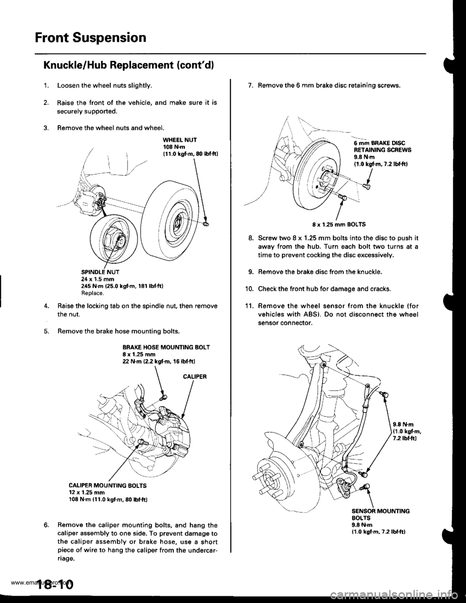
1.Loosen the wheel nuts slightly.
Raise the front of the vehicle, and make sure it is
secu.ely supported.
Remove the wheel nuts and wheel.
SPINDLE NUT24 x 1,5 mm245 N.m (25.0 kgf.m, 181 lbtft)Replace.
Raise the locking tab on the spindle nut, then remove
the nut.
Remove the brake hose mounting bolts.
BRAKE HOSE MOUNTING BOLT8 x 1.25 mm22 N.m {2.2 kgt m, 16 lbtft)
CALIPER MOUNTING BOLTS12 x 1.25 mm108 N.m (11.0 kgl.m, 80 lbl.ft)
Remove the caliper mounting bolts, and hang the
caliper assembly to ona side. To prevent damagg to
the caliper assembly or brake hose, use a shortpiece of wire to hang the caliper from the undercar-
riage.
18-10
7. Remove the 6 mm brake disc retaining screws,
6 mm BRAKE DISCRETAINING SCREWS9.8 N.m(1.0 kgl.m,7.2 lbf.ftl
8.
8 x 1.25 mm BOLTS
Screw two 8 x 1.25 mm bolts into the disc to push it
awav from the hub. Turn each bolt two turns at a
time to prevent cocking the disc excessively,
Remove the brake disc from the knuckle.
Check the front hub for damage and cracks.
11. Remove the wheel sensor from the knuckle (for
vehicles with ABS). Do not disconnect the wheel
sensor connector.
9.8 N.m(1.0 kgf.m,7.2 tbttrl
MOUNTINGBOLTS9.8 N.mlr.0 kgf.m, ?.2lbf.ftl
www.emanualpro.com
Page 916 of 1395
Front Damper
Reassembly
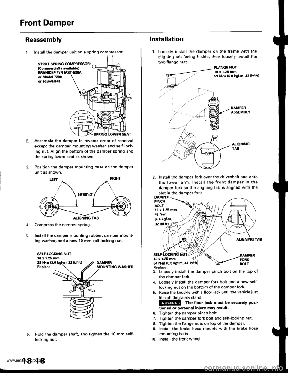
1. Install the damper unit on a spring compressor.
STRUT SPflNG COMPBESSOR:lcomm.rcillly .vrilrble)BRANICKC T/N MST.sEOAor Mod.l 7200or oquivtla
SPRING LOWER SEAT
Assemble the damper in reverse order of removal
except the damper mounting washer and self lock-
ing nut. Align the bottom of the damper spring and
the spring lower seat as shown.
Position the damper mounting base on the damper
unit as shown.
Compress the damper spring,
Install the damper mounting rubber, damper mount-
ing washer, and a new 10 mm self-locking nut.
SELF-LOCKING NUT10 x 1.25 mmZt N.m 13.0 kgf.m, 22 lbf.ft)Replace.
Hold the damper shaft, and tighten the
locking nut.
DAMPERMOUNfING WASHER
18-18
10 mm self-
1.
lnstallation
Loosely install the
aligning tab facing
two flange nuts.
damper on the frame with
inside, then loosely install
FLANGE NUT
the
tne
-__---a-"- 10 x 1.25 mmg*- 59 N.m {5.0 kgt m, 43 tbf.ftl
| -,./.46- --...
./ -4 A-
DAMPERASSEMBLY
ALIGNINGTAB
2, Install the damper fork over the driveshaft and onto
the lower arm. Install the front damper in the
damper fork so the aligning tab is aligned with the
slot in the damDer fork,
3. Loosely install the damper pinch bolt on the top of
the damper fork.
4. Looselv install the damper fork bolt and a new self-
locking nut on the bottom of the damper fork.
5. Raise the knuckle with a floor iack until the vehicle just
lifts off the safetv stand.
The lloor iack must b€ socurely posi-
tioned or personal iniury may result.
6. Tighten the damper pinch bolt.
7. Tighten the damper fork bolt and self-locking nut.
8. Tighten the flange nuts on top of the damper.
9. Install the brake hose mounts with the brake hose
mounting bolts.
10. Installthe front wheel.
10 x 1.25 mmil3 l+m
{4.4 kgf'm,
Replace.
www.emanualpro.com
Page 925 of 1395
Brakes
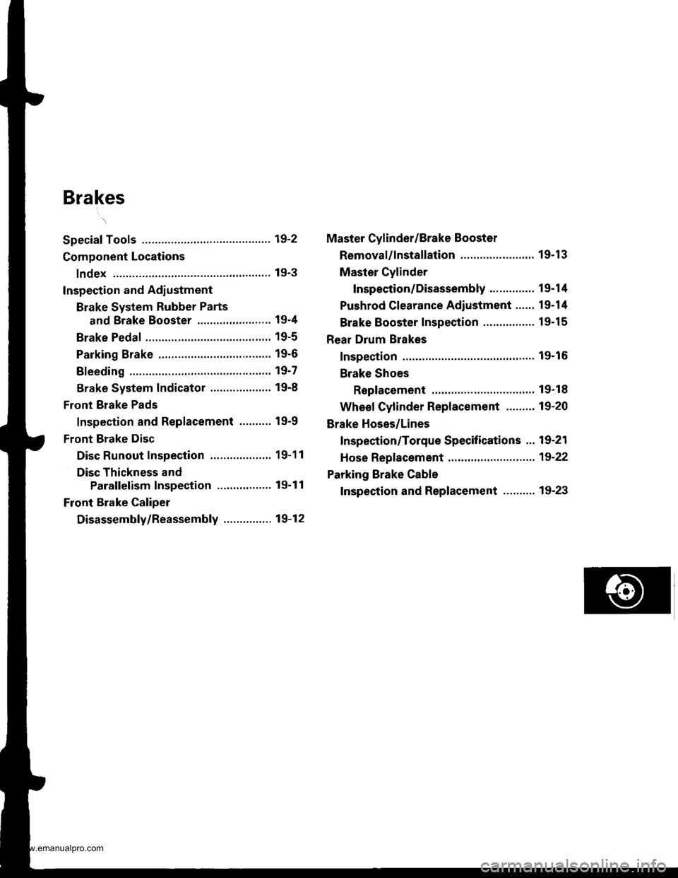
Special Tools ............. 19-2
Component Locations
lndex ................ ...... 19-3
Inspection and Adlustment
Brake System Rubber Parts
and Brake Booster ..........,,,.......... 19-4
Brake Pedal ............ 19-5
Parking Brake ........ 19-6
Bleeding ................. 19'7
Brake System Indicator ................... 19-8
Front Brake Pads
Inspection and Replacement .......... 19-9
Front Brake Disc
Disc Runout Inspection ................... 19-11
Disc Thickness and
Parallelism Inspection ........,........ 19-1 1
Front Brake Caliper
Disassembly/Reassembly ............... 19-12
Master Cylinder/Brake Booster
Removal/lnstallation ....................... 19-13
Master Cylinder
Inspection/Disassembly .............. 19-14
Pushrod Clearance Adiustment ...... 19-14
Brake Booster Inspection ...,.,,,,....... 1 9-1 5
Rear Drum Brakes
Inspection .............. 19-15
Brake Shoes
Replacement ..... 19-r 8
Wheel Cylinder Replacement ......... 19-20
Brake Hoses/Lines
Inspection/Torque Specifications ... 19-21
Hose Replacement ....,...,............. ..,,, 19-22
Parking Brake Cable
Inspection and Replacement .......... 19-23
www.emanualpro.com
Page 927 of 1395
Gomponent Locations
lndex
ERAKE SYSTEM INOICATORCircuit Diagram, page't9-8
PARKING BRAKEAdjustment, page 19-6Parking Brake Switch Test, page '19-8
PARKING BRAKE CABI..EInspection and Replacement,page 19-23
BRAKE BOOSTERBrake Booster Inspection, page 19-15
Removal/lnstallation, page 19 13
MASTER CYLINDER
Inspection, pago 19-16Brake Shoes Replacement,page 19-18Wheel CylinderReplacement, page 19-20
REAR DRUM BRAKE
Removal/lnstallation, page 19-13lnspection/Disassembly.page 19-14Pushrod Clearance Adjustment,page 19 ldBrake Fluid LevelSwitch Test,page 19-8
Inspection/Torque Specification, pag€'19-21
Hose Replacement, Page 19-22
Front Brake Pads, page 19-9Front Brake Disc. page 19-11Front Brake Caliper, page 19-12
)i't ' -"''
/'"''t,'..,1 ...,. , \,,,.
i ,.'
'a.,
I
.) ..)
t ^fl)
19-3
www.emanualpro.com
Page 928 of 1395
Inspection and Adjustment
Brake System Rubber Parts and Brake Booster
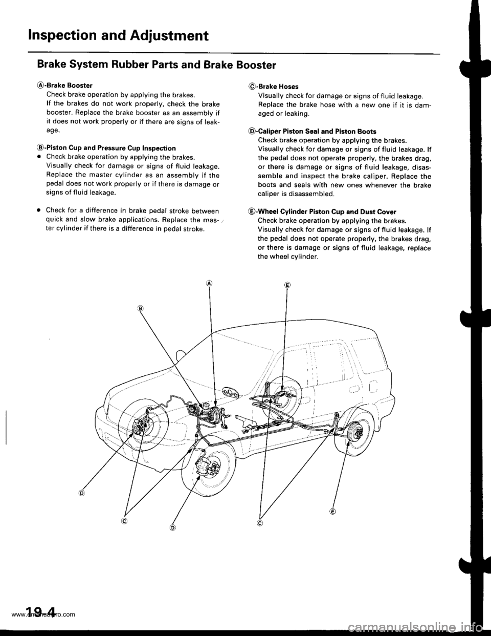
@-Brake Booster
Check brake operation by applying the brakes.
lf the brakes do not work properly, check the brake
booster. Replace the brake booster as an assembly ifit does not work properly or if there are signs of leak-
age.
@-Piston Cup and Pressure Cup Inspection. Check brake operation by applying the brakes.
Visually check for damage or signs of tluid leakage.Replace the master cylinder as an assembly if thepedal does not work properly or if there is damage orsigns of fluid leakage.
. Check for a difference in brake pedal stroke betweenquick and slow brake applications. Replace the mas-.
ter cylinder if there is a difference in pedal stroke.
(9-Brake Hoses
Visually check for damage or signs of fluid leakage.
Replace the brake hose with a new one if it is dam-
aged or leaking.
O-Caliper Piston S€al and Piston Boots
Check brake operation by applying the brakes.
Visually check for damage or signs of fluid leakage. lf
the pedal does not operate properly, the brakes drag,
or there is damage or signs of fluid leakage, disas-
semble and inspect the brake caliper. Replace the
boots and seals with new ones whenever the brake
caliper is disassembled.
@-Wheel Cylinder Piston Cup and Dust Cover
Check brake operation by applying the brakes.
Visually check for damage or signs of fluid leakage. lf
the pedal does not operate properly, the brakes drag,
or there is damage or signs of fluid leakage, replace
the wheel cvlinder.
19-4
www.emanualpro.com
Page 933 of 1395
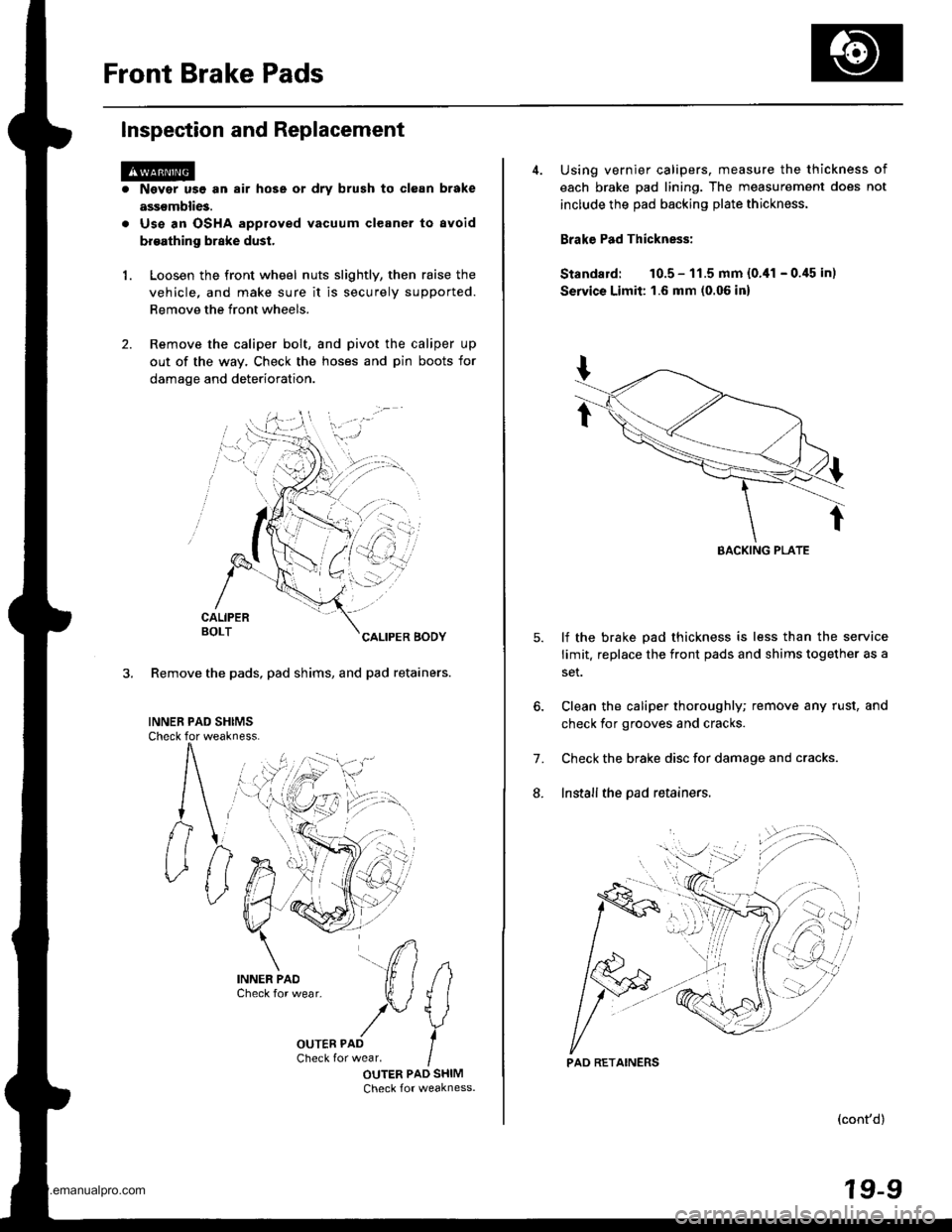
Front Brake Pads
Inspection and Replacement
1.
Nsvgr u9e an air hose or dry brush to clean brake
assemblies.
Use an OSHA approved vacuum cleaner to avoid
broathing brake dust.
Loosen the front wheel nuts slightly, then raise the
vehicle, and make sure it is securely supported.
Remove the front wheels.
Remove the caliper bolt, and pivot the caliper up
out of the way. Check the hoses and pin boots for
damage and deterioration.
CALIPERBOLTCALIPER BODY
3. Remove the pads, pad shims, and pad retainers.
INNEB PAD SHIMSCheck for weakness.
#
IOUTER PAD SHIMCheck for weakness.
i)n.
4. Using vernier calipers, measure the thickness of
each brake pad lining. The measurement does not
include the pad backing plate thickness.
Brake Pad Thickness:
Standard: 10.5 - 11.5 mm {0.,11 - 0.45 in)
Servics Limit: 1.6 mm (0.06 in)
lf the brake pad thickness is less than the service
limit. replace the front pads and shims together as a
set.
Clean the caliper thoroughly; remove any rust, and
check for grooves and cracks.
Check the brake disc for damage and cracks.
Install the pad retainers.
7.
L
(cont'd)
19-9
EACKING PLATE
'.'..i
PAD RETAINERS
www.emanualpro.com