1997 HONDA CR-V service
[x] Cancel search: servicePage 975 of 1395
![HONDA CR-V 1997 RD1-RD3 / 1.G Workshop Manual
Troubleshooting
DTG 54: Main Relay
IWHT/GRNI
AAS CONTROL UNIT 26P CONNECTON
Wire side of female terminals
ABS COf{TROL UN]T 22P CONNECTOR
PCOMIGRN/WHTIscoM{BLK/WHTI
Wire side of female terminals
- Wi HONDA CR-V 1997 RD1-RD3 / 1.G Workshop Manual
Troubleshooting
DTG 54: Main Relay
IWHT/GRNI
AAS CONTROL UNIT 26P CONNECTON
Wire side of female terminals
ABS COf{TROL UN]T 22P CONNECTOR
PCOMIGRN/WHTIscoM{BLK/WHTI
Wire side of female terminals
- Wi](/manual-img/13/5778/w960_5778-974.png)
Troubleshooting
DTG 54: Main Relay
IWHT/GRNI
AAS CONTROL UNIT 26P CONNECTON
Wire side of female terminals
ABS COf{TROL UN]T 22P CONNECTOR
PCOMIGRN/WHTIscoM{BLK/WHTI
Wire side of female terminals
- With the ignition switch ON(lll, the ABS indicator doesnot go off.- With the SCS service connec-tor connected {see page 19-381,DTC 54 is indicatod.
Check the ABS +B 120 A) fuse inthe under-hood ABS luse/relaybox, and reinstall the fuse if it isoK.
FeDlace the tu3e and recheck.
Ch€ck tor an open in the 81, 82circuit:Measure the voltage betweenbody ground and the ABS controlunit 26P connector terminal No. 14and No. 15 individually.
Repair open in the wiro bstweonth6 ABS conirol unit and theunder-hood ABS fuse/rolay box,
ls there battery voltage?
Check for a short to body groundin the PMR circuit:L Turn the ignition switch OFF.2. Remove the pump motor relay.3. Disconnect the ABS controlunit 22P connector.4. Check lor continuity betweenterminal No. 19 and bodygrouno.
Repair short to body ground inthe wire betweon the under-hood ABS lGe/r.lay box and theABS control unit.
Check for a short to body groundin the PCOM, SCOM cilcuit:1. Disconnect the ABS controlunit 26P connector.2. Check tor continuity betweenbody ground and the ABS con-trol unit 26P terminals No- 1and No.2 individually.
. R€pair short to body ground inth€ P1COM circuit wire betweenthe ABS control unit and theund6r-hood ABS tuse/r6layoox.. R6p.ir short to body ground inthe PCOM or SCOM circuit wirebetweon th6 ABS control unitand lhe mod!lator unit.. R.Dlece tho modulrtor unit.(Short circuit inside the unitl
ls there continuity?
(To page 19-53)
www.emanualpro.com
Page 1021 of 1395
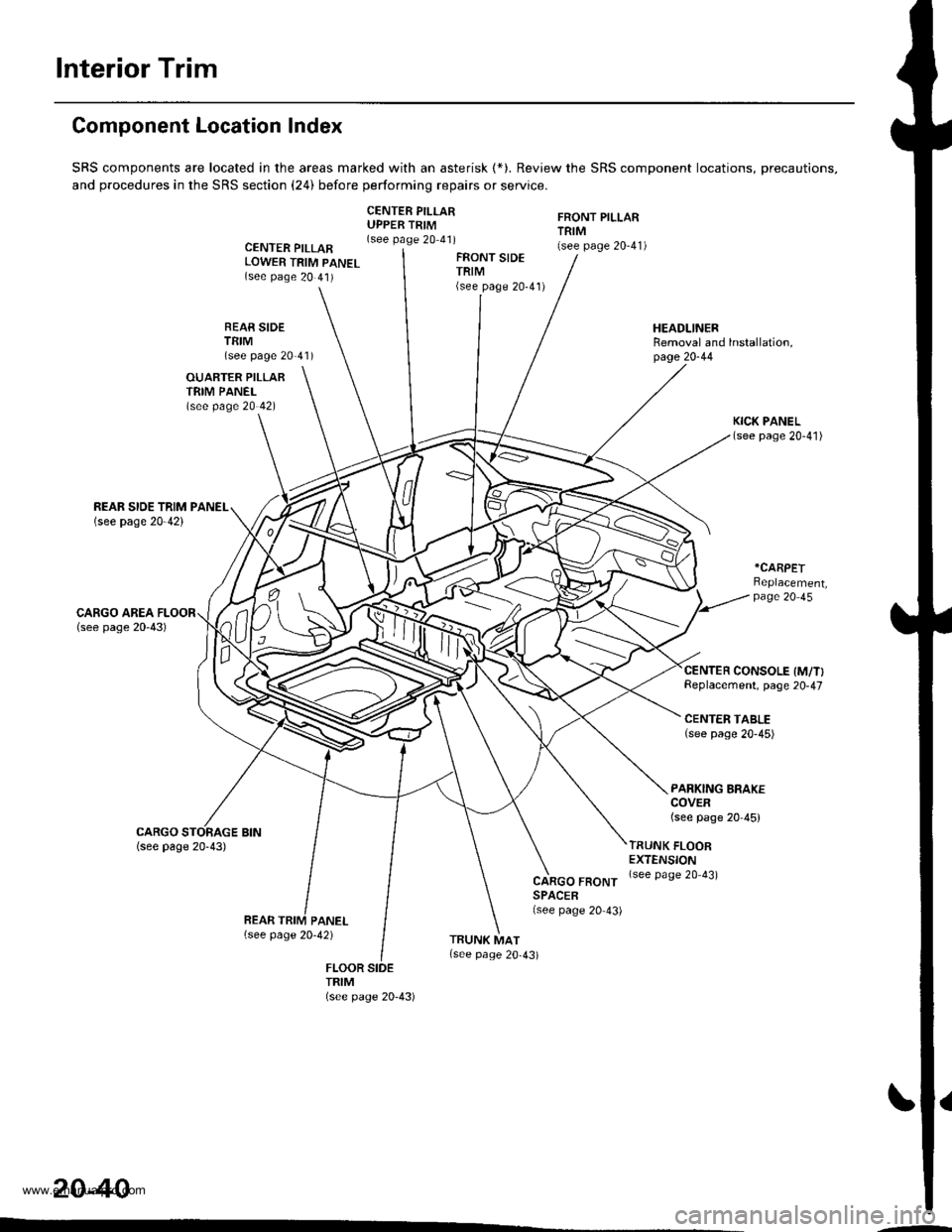
lnterior Trim
20-40
CARGO FRONTSPACER(see page 20 43)
FRONT PILLARTRIM(see page 20-41)
TRUNK FLOOREXTENSION(see page 20 43)
HEADLINERRemoval and lnstallation,page 20-44
Component Location Index
SRS components are located in the areas marked with an asterisk (*). Review the SRS component locations, precautions,
and procedures in the SRS section (24) before performing repairs or service.
CENTER PILLARUPPER TRIM(see page 20 41)CENTER PILLARLOWER TRIM PANEL(see page 20 41)
FRONT SIDETRIM(see page 20-41)
BEAR SIDETEIM(see page 20'41)
OUARTER PILLARTRIM PANEL(see page 20 42)
*CARPET
Replacement,page 20 45
CENTER CONSOLE IM/T}Replacement, page 20-47
CENTEN TABLE(see page 20-45)
PARKING BRAKECOVER(see page 20-45)
TRIM
www.emanualpro.com
Page 1026 of 1395
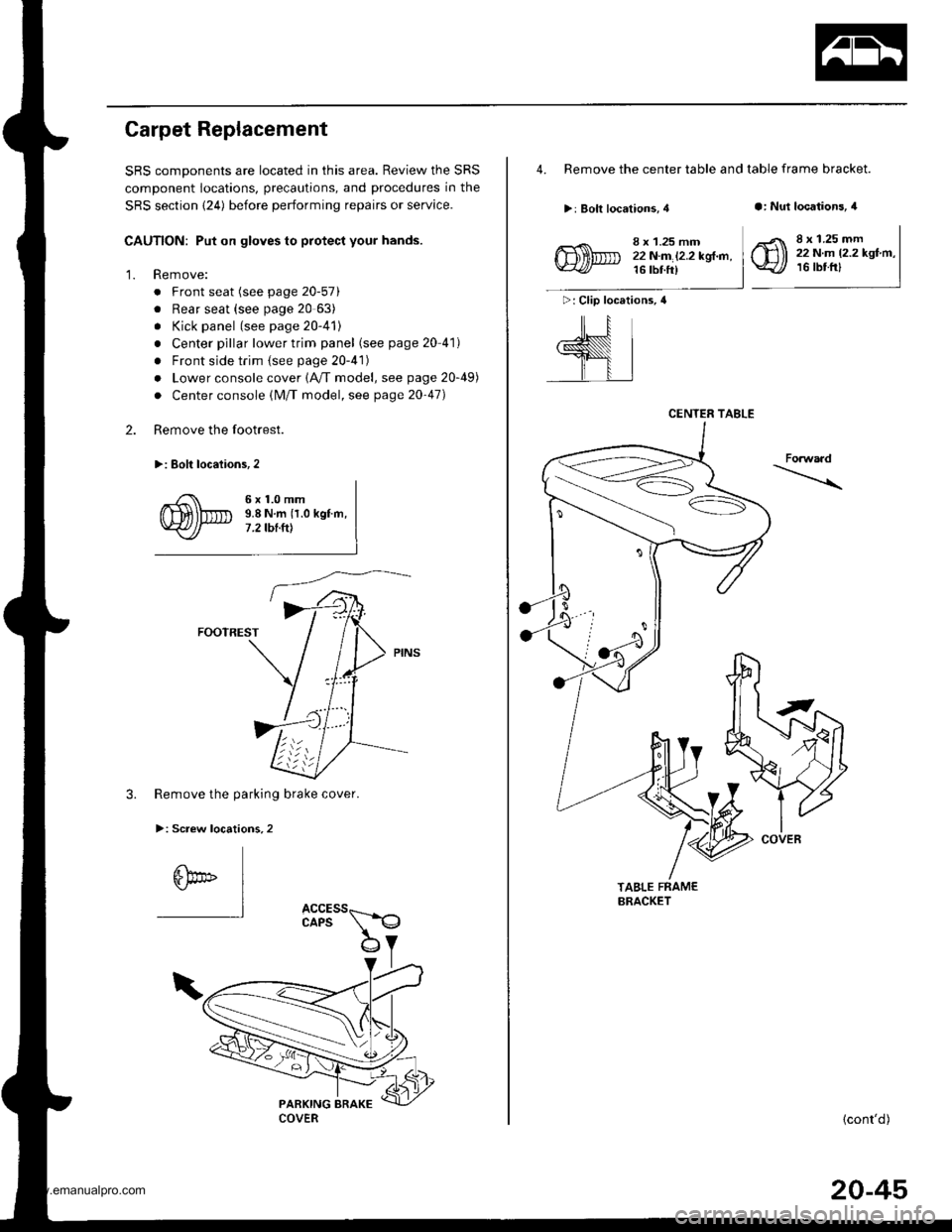
Carpet Replacement
SRS comDonents are located in this area. Review the SRS
component locations, precautions, and procedures in the
SRS section {24) before performing repairs or service.
CAUTION: Put on gloves to protect your hands.
Remove:
. Front seat (see page 20-571
. Rear seat (see page 20 63)
. Kick panel (see page 20-41)
. Center pillar lower trim panel (see page 20 41)
. Front side trim {see page 20-41)
. Lower console cover 1A,/T model, see page 20-49)
. Center console (lM/T model, see page 2o-47)
Remove the footrest.
>: Eolt locaiions,2
2.
'1.
6x1.0mm9.8 N.m {1.0 kgf.m,7 .2 tbt.ttt
FOOTREST
3. Remove the parking brake cover.
>: Screw locations,2
6bo" I"l
4. Remove the center table and table frame bracket.
>: Bolt locations, 4a: Nut locations, 4
>: Clip locations, 4
ill
,l
8 x 1.25 mm22N.m l2.2kgl.n,16 tbt ft)
8 x 1.25 mm22 N.m 12.2 kgf.m,16 tbtfrl
Forwaad
TABLE FRAMEBRACKET
{cont'd)
CENTER TABLE
COVER
20-45
www.emanualpro.com
Page 1029 of 1395
Dashboard
SRS components are located in this area. Review the SRS
component locations, precautions, and procedures in the
SRS section (24) before performing repairs or service.
GAUTION:
. When prying with a tlat-tip screwdriver, wrap h withproteqtive tape, and apply protective tape around the
relat€d parts, to prevent damage,
. Put on glovgs to protect your hands.
NOTE: Take care not to scratch the dashboard and relatedpans.
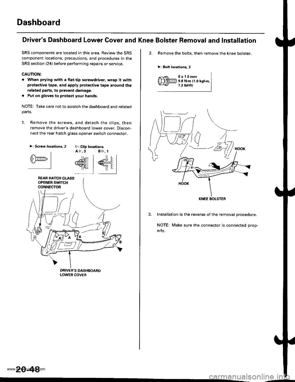
1. Remove the screws, and detach the clips, then
remove the driver's dashboard lower cover. Discon-
nect the rear hatch glass opener switch connector.
>: Clip locationsA >,3 B>, 1
rr.- | lr, l
@, | €{lr'" 1 |'l
>: Screw locations,2
IGlTtrrrb I.-l
REAR HATCH GLASSOPENER SWITCHCONNECTOR
20-48
'-
Driver's Dashboard Lower Cover and Knee Bolster Removal and Installation
2. Remove the bolts. then remove the knee bolster.
>: Boh locations,3
6x1.0mm9.8 N.m ('1.0 kgtm.7.2 tbtftl
3. Installation is the reverse of the removal procedure.
NOTE: Make sure the connector is connected prop-
erly.
KNEE BOLSTEF
www.emanualpro.com
Page 1031 of 1395
Dashboard
Center Dashboard Lower Gover
Removal and Installation
SRS components are located in this area. Review the SRS
component locations, precautions, and procedures in the
SRS section {24) before performing repairs or service
CAUTION:
. Wh€n prying with a flat-tip screwdrivet, wrap it with
protective tap€, and apply proteclive tape around the
rslated parts to prevenl damage.
. Put on glovgs to protect your hands.
NOTE: Take care not to scratch the dashboard and related
oarts.
1. Remove:
. Driver's dashboard lower cover (see page 20-48)
. Glove box (see page 20-49)
. Center pocket (AVT model. see page 20-49)
. Center console (M/f model, see page 20-41l,
. Center upper pocket (M/T model, see page 2O-47J
2. Remove the screws, and detach the clips. then
remove the center dashboard lower cover.
Disconnect the connectors.
>: Screw locationa,.a
I
6br" I-l
3. Installation is the reverse of the removal procedure-
NOTE: Make sure the connectors are connected
properly.
20-50
>: Clip loc.tion6,3
I5
\"P I AccEssoRyI socKET
Center Panel Removal and
lnstallation
SRS components are located in this area. Review the SRS
comDonent locations, precautions, and procedures in the
SRS section (24) before performing repairs or servace.
CAUTION:
. When prying with a flat-tip screwdriver, wrap it with
protective tape, and apply protective tape around the
relatgd parts to prevent damage.
. Put on gloves to protect your hands.
NOTE: Take care not to scratch the dashboard and related
parts.
1. Remove:
. Driver's dashboard lower cover (see page 20-48)
. Glove box (see page 20-49)
. Center pocket (A,/T model, see page 20-49)
. Center console (M/T model, see page 20-47)
. Center upper pocket {M/T model, see page 20-47)
. Center dashboard lower cover
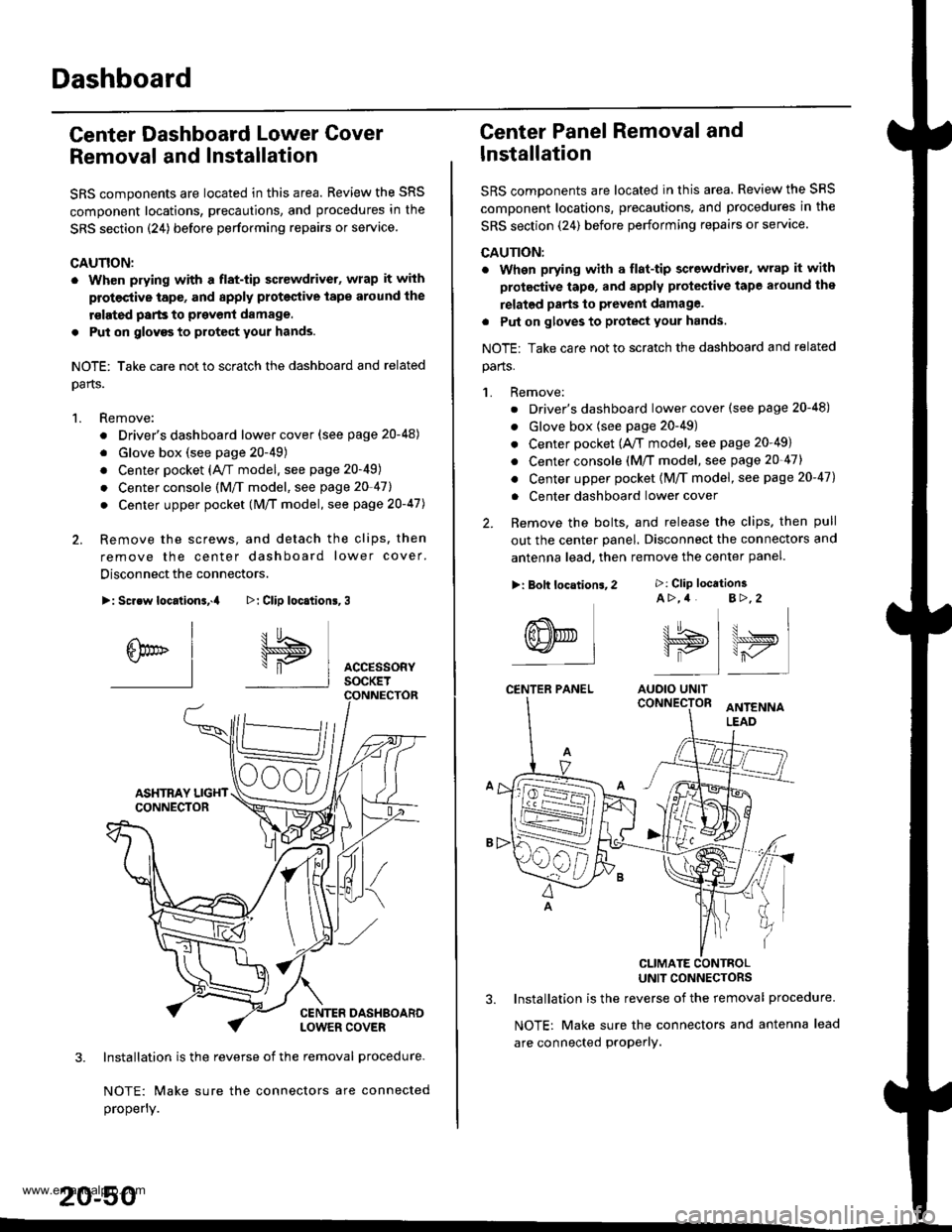
2. Remove the bolts, and release the clips. then pull
out the center panel. Disconnect the connectors and
antenna lead. then remove the center panel.
CLIMATE CONTBOLUNIT CONNECTORS
3. Installation is the reverse of the removal procedure.
NOTE: Make sure the connectors and antenna lead
are connected proPerly.
>: Clip location3A >,4 B>,2
tt.t !^ t u . I\lJS>,, \>ryI is I r-,/'
AUOIO UNIT
>: Bolt locations,2
(8NED L-l
CENTER PANEL
www.emanualpro.com
Page 1034 of 1395
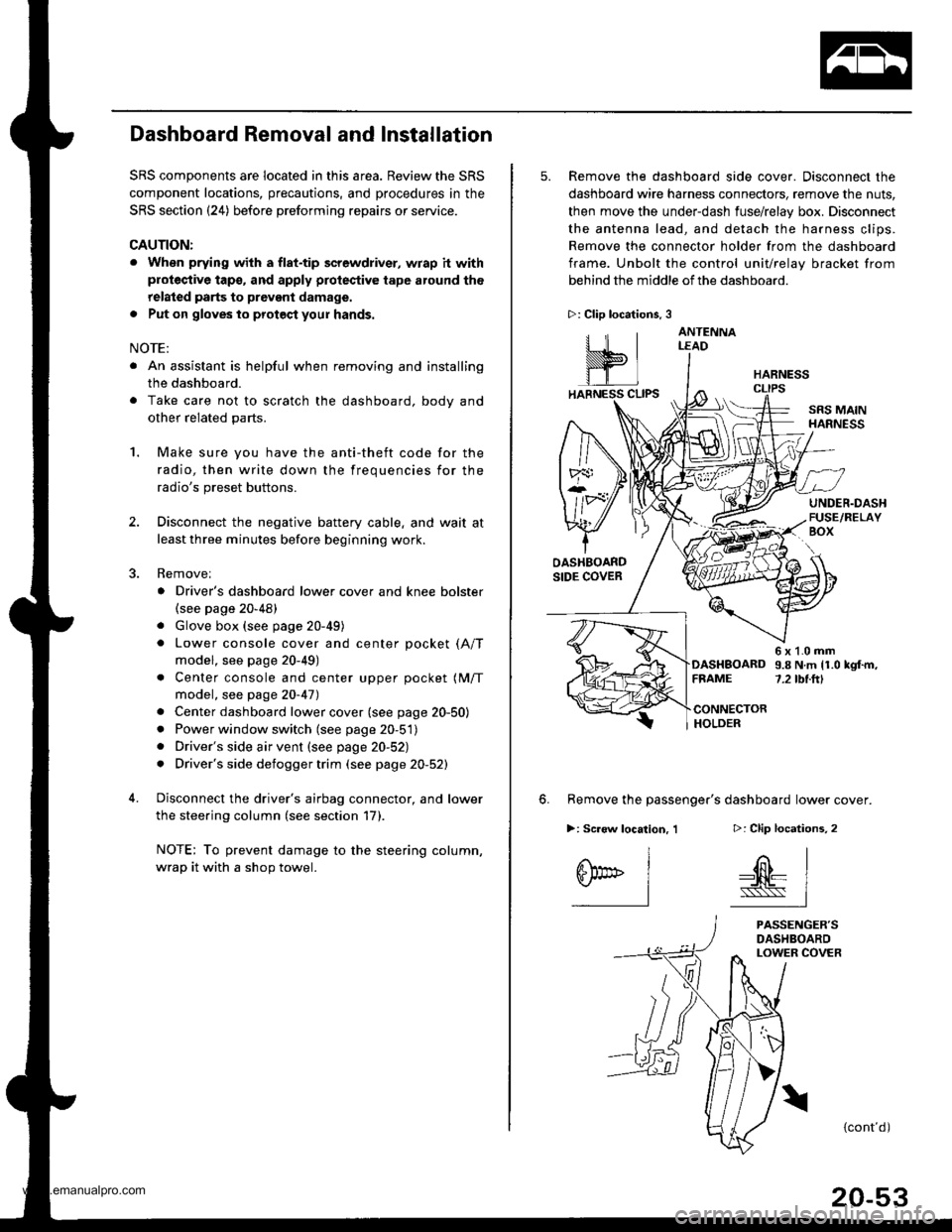
Dashboard Removal and Installation
SRS components are located in this area. Review the SRS
component locations, precautions, and procedures in the
SRS section {24) before preforming repairs or service.
CAUTION:
. When prying with a flat-tip screwdriver, wrap h withprotective tap€, and apply protective tape around the
related parts to prevgnt damage.
. Put on gloves to prot€ct your hands.
NOTE:
. An assistant is helpful when removing and installing
the dashboard.
. Take care not to scratch the dashboard, bodv and
other related parts.
1.Make sure you have the anti-theft code for the
radio, then write down the frequencies for the
radio's preset buttons.
Disconnect the negative battery cable. and wait at
least three minutes before beginning work.
Removei
a Driver's dashboard lower cover and knee bolster(see page 20-48)
. Glove box (see page 20-49)
. Lower console cover and center pocket (A/T
model, see page 20-49)
. Center console and center upper pocket (M/T
model, see page 20-47)
. Center dashboard lower cover (see page 20-50)
. Power window switch (see page 20-51)
. Driver's side air vent (see page 20-52)
. Driver's side defogger trim (see page 20-52)
Disconnect the driver's airbag connector, and lower
the steering column (see section 17)
NOTE: To prevent damage to the steering column,
wrap it with a shop towel.
2.
5. Remove the dashboard side cover. Disconnect the
dashboard wire harness connectors, remove the nuts,
then move the under-dash fuse/relay box. Disconnect
the antenna lead, and detach the harness clips.
Remove the connector holder from the dashboard
frame. Unbolt the control unit/relay bracket from
behind the middle of the dashboard.
HARNESS
6. Remove the passenger's dashboard lower cover.
D: Clip locations,
nl
-$t- Issj
I
ANTENNALEAD
>: Clip locations.
rttl
slllll
>: Scr€w location, 1
I
SF:oo I-l
SRS MAINHARNESS
UNDER.DASHFUSE/RELAYBOX
OASHBOARDSIDE COVER
6x1.0mm9.8Nm11.0kgf.m,7.2tbt.ftlDASHBOARDFFAME
CONNECTORHOLDER
PASSENGER'SDASHBOARDLOWER COVER
{cont'd)
www.emanualpro.com
Page 1090 of 1395
a
Heater and Air Conditioning
Heater ...........21
NOTE: Section 21 ("Heater") is included in section 22.
Air Conditioning ......'..'.. '.'22'1
SUPPLEMENTAL RESTRAINT SYSTEM (SRS}
This model has an SRS which includes a driver's airbag in the steering wheel hub, a passenger's airbag in the dashboard
above the glove box ('97,00 models). and seat belt tensioners in the seat belt retractors ('98 - 00 models). Information
necessary to safely service the SRS is included in this Service Manual. ltems marked with an asterisk (*) on the contents
page include. or are located near, SRS components. Servicing, disassembling or replacing these items will require special
precautions and tools, and should only be done by an authorized Honda dealer.
@. To avoid rendering the SRS inoperative, which could lead to personal iniury or death in the event of 8 severe frontal
collision, all SRS service work must be performed by an authotized Honda dealer.
lmproper service procedures, including incorrect removal and installation of the SRS, could lead to personal iniury
caused by unintentional deployment of the airbags ('97 - 00 models), and seat belt tensioners 138 - 00 models).
Do not bump the SRS unit. Otherwise, the system may fail in case of a collision, or the airbags may deploy when the
ignition switch is ON {lll.
SRS eleqtrical wiring harnesses are identified by yellow color coding. Related components are located in the steering
column, front console, dashboard, dashboard lower panel, and in the dashboard above the glove box. Do not use elec-
tricaltest equipment on thes€ cilcuils.
www.emanualpro.com
Page 1091 of 1395
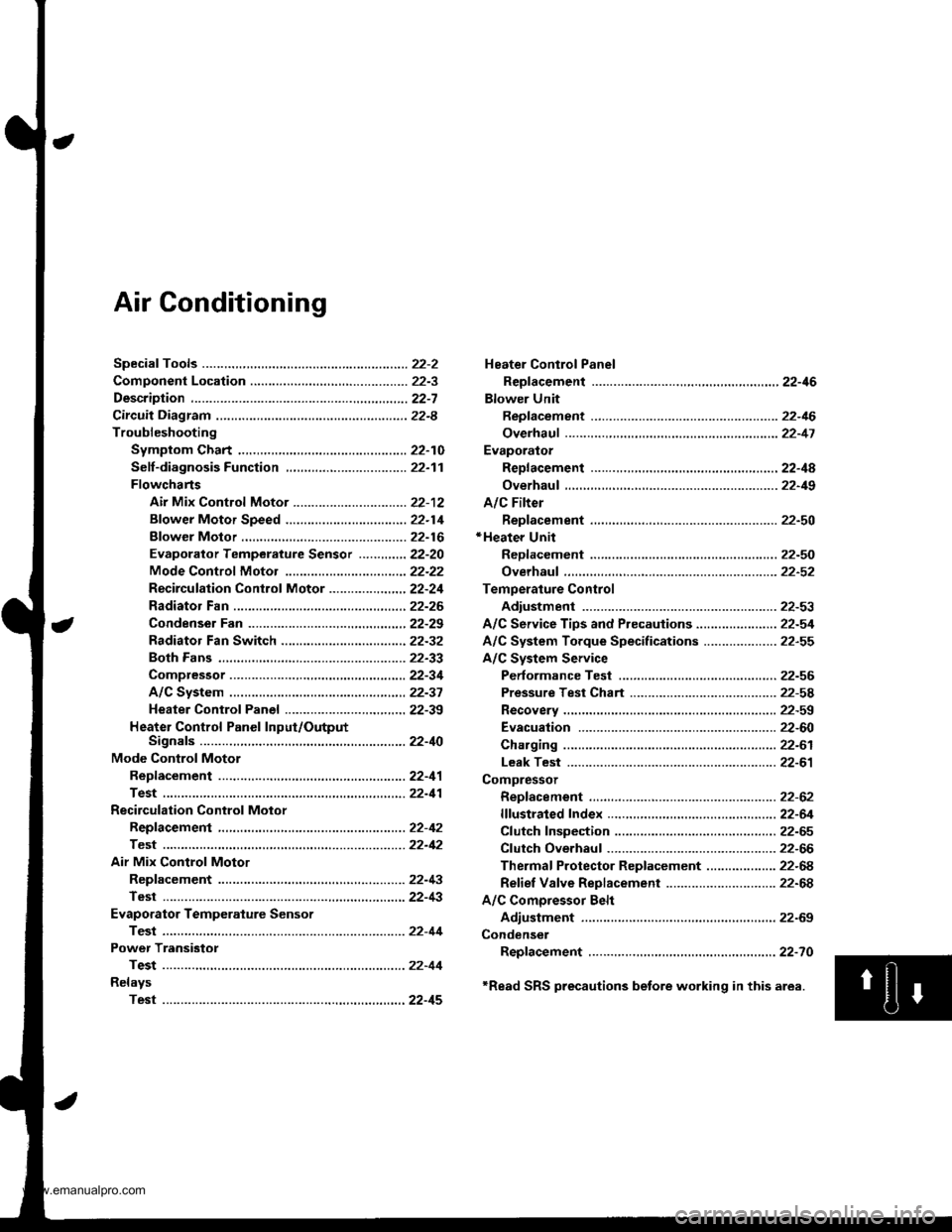
Air Conditioning
Heater Control Panel
Reofacement ,.,...,,.,..,.,.,,22-46
Blower Unit
Replacement .................. 22-46
Overhaul ...........,,,., .......-.22-17
Evaporalor
ReDlacement ...,.,.,..,......,22-4A
Overhaul ................ .........22-19
A/C Filter
Replacement ..................22-50*Heater Unit
ReDfacement ..................22-50
Overhaul ..,.,..,.,...,.. .........22-52
Temperature Control
Adiustment ....................22-53
A/C Service Tips and Precauiions............-....-.... 22-54
A/C System Torque Specifications .................... 22-55
A/C System Service
Performance Test ......,...22-56
Pressure Test Chart .-.....22-5a
Recovery ..............,. ...-.-...22-59
Evacuation -...........-........22-60
Charging ................ .......-.22-61
Leak Test ........................22-61
Compressor
Repfacement ..........-.......22-62
flfustrated Index .....,.......22-64
Cfutch fnspection .........,.22-65
Cfutch Overhaul ............- 22-66
Thermaf Protector Rep|acement ................... 22-68
Refief Valve Replacement .............................. 22-68
A/C Comoressor Belt
Adiustment .................... 22-69
Condenser
Repfacement .,.....,,.,..,.,..22-70
'Read SRS precautions betore working in this area.
www.emanualpro.com