1997 HONDA CIVIC Wire door
[x] Cancel search: Wire doorPage 399 of 2189
PGM-FI System
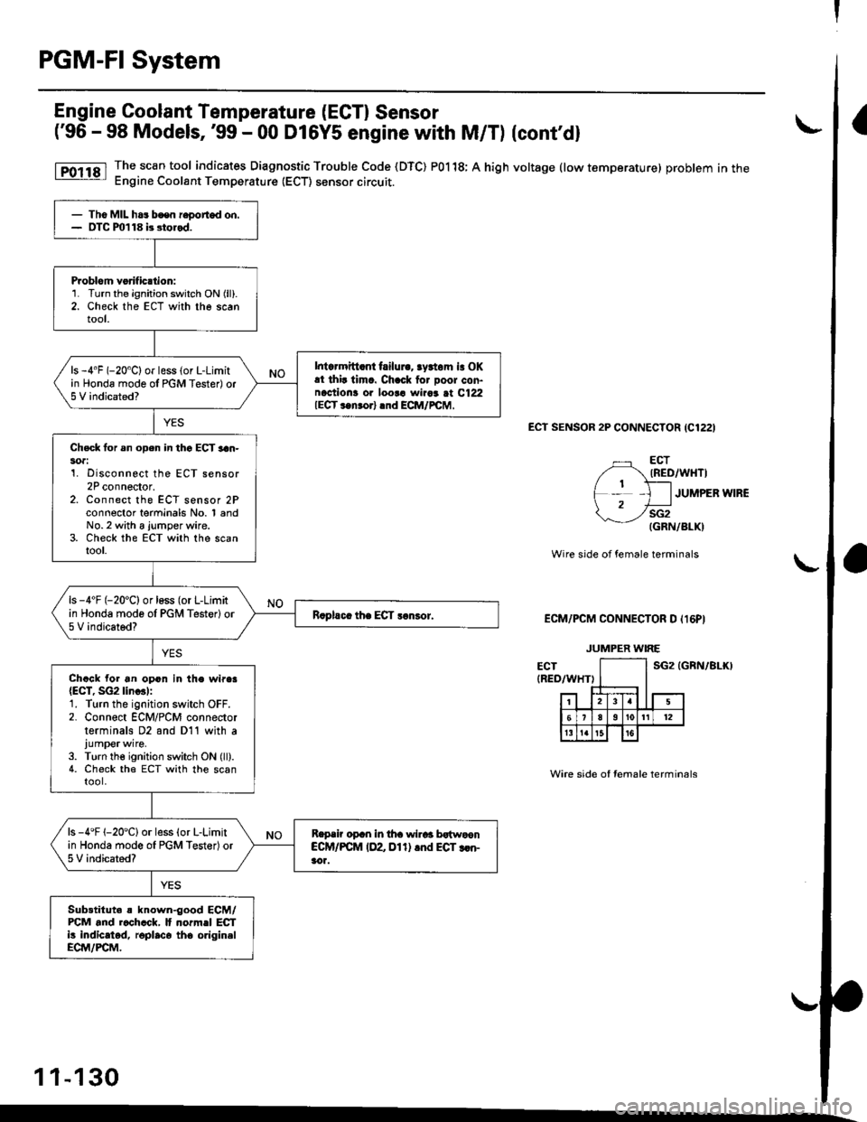
Engine Coolant Temperature (ECT) Sensor
('96 - 98 Models,'99 - 00 D16YS engane with M/T) (cont'd)
The sc€n tool indicates Diagnostic Trouble Code (DTC) P0118; A high voltage (low temperature) problem in theEngine Coolant Temperature (ECT) sensor circuit.
ECt SENSOR 2P CONNECTOR {C1221
ECTIRED/WHTI
JUMPER WIRE
sG2(GRN/BLK)
Wire side of female terminals
ECM/PCM CONNECTOR D Il6PI
sG2 tGRN/81r0
Wire side of Iemale terminals
- Tho MIL ha3 bcen r€oorted on.- OTC m118 b stored.
Problom vorificttion:1. Turn the ignition switch ON (ll).
2. Check the ECT with the scantool.
Intcrmitt.nt failui.. rydom is OKat thir timc. Chack for Door con-naction! or loor! wiaar at C122IECT ..n.orl .nd ECM/rcM,
ls -4"F (-20'C) or less (or L-Limitin Honda mode ol PGM Tester) or5 V indicated?
Chsck lor sn open in thc ECT 3an-soa:1. Disconnect the ECT sensor2P connector.z. Lonnecr rne ELt sensor zFconnector terminals No. 1 andNo.2 with a jumper wire.3. Check the ECT with the scantool.
ls -4'F (-20'C) or loss (or L-Limitin Honda mode ol PGM Testerlor5 V indicated?
Chack for an opon in the wire.{ECT, SG2lin..l:1. Turn the ignition switch OFF.2. Connect ECM/PCM connectorterminals D2 and D11 with ajump€rwire.
3. Turn the ignition switch ON (ll).4. Check the ECT with the scantool.
ls -4'F 1-20'Clor less (o. L-Limitin Honda mode ol PGM Tester)or5 V indicated?
Reprir oprn in tha wirar bstwoonCCM/PCM IDZ Dl1) .nd EGT rcn-aor.
Sub3titut. s known-good ECM/FCM and r.chcck, It normel ECTi! indicatod, roplaco tho origin.lECM/PCM.
JUMPER WIRE
1 1-130
Page 401 of 2189

PGM-FI System
Throttle Position ITP) Sensor ('96 - 98 Models,'99 - 00 D16Y5 engine with M/Tl
The scan tool indicates Diagnostic Trouble Code (DTC) P0122: A low voltage problem in the Throttle Position(TP) sensor circuit.
The TP Sensor is a potentiometer. lt is connected to the throttle valve shaft. As the throttle position changes, the throttleposition sensor varies the voltage signal to the ECM/PCM.
OUTPUT VOLTAGE IVI
1
2
1
0
s{i2(GRN/BLKI
THROTTLEOPENING
FULLTHROTTLE
TP SENSOR 3P CONNECTOR ICllOI
vocz(YEL/BLUI
Wire side ot femal6 terminals
ECM/PCM CONNECTOR D IT6PI
SG2 IGRN/ALKI
{To page l1-133)
Terminal side of male terminals
11-132
- Tho MIL h63 boon roportod on.- DTC m122 i. storcd.
Probl6m voritic€tion:1. Turn the ignition switch ON (ll).
2. Check the throttle positionwith the scan tool.
ls there approx. .49 V whenthe throttle is fully closed andapprox. 4.5 V when the throttleis lully op6ned?
Int..mittent tailura, rFiem ir OKat thit tima. Chock tor Door con-nections or loorc wires !t C110ITP lonrorl .nd ECM/FCM.
Ch6ck lor rn opon in the wire(VCC2linel:
1. Turn the ignition switch OFF.2. Disconnect ths TP sensor 3Pconnector.3. Turn the ignition switch ON lll).4, Measure voltage betweenthe TP sensor 3P conn€ctor ter-minals No. l and No.3.
ls there approx. 5 V?
Check for rn opcn in wire IVCC2line):Measure voltage between ECM/PCM conneclor terminals D10 and011.Chock for rn open or 3hort in TPlon30t:1. Turn the ignition switch OFF.2. At the s€nsor side, measureresistance between the TP sen-sor terminals No. 1 and No. 2with the throttle fully closed.
Roplir op€n in thg wiro batwcsnECM/PCM {DlO) rnd TP ren3or.ls there approx.5 V?
Substitut6 r known-good ECM/PCM and rach6ck. lf pro$ribodvohrge i! now avrilablc, replac€tho o.iginel €CM/FCM.
Wire side of female terminals
Page 419 of 2189
PGM-FI System
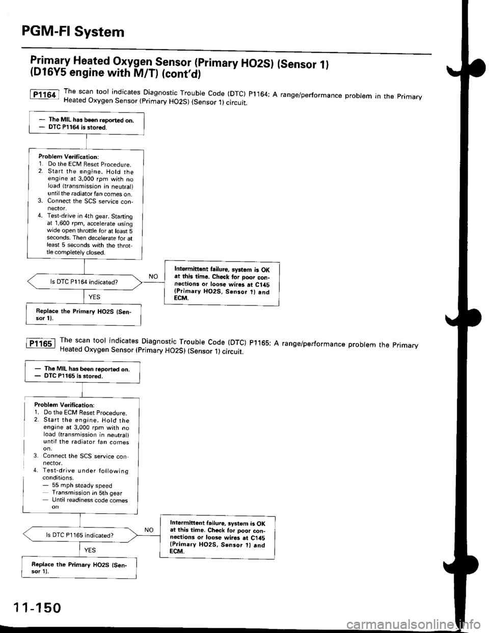
l:in1.".fy Heated Oxygen Sensor (primary HO2SI (sensor 1l(D16Y5 engine with M/D (cont'd)
The scan toor indicates Diagnosti" -Tl:y|* code (DTC) pl164: A range/performance probrem in the primaryHeated Oxygen Sensor (primary HO2S) (Sensor 1)circuit.
The scan tool indicates Diagnostic Trouble Code (DTC) p1165: AHeated Oxygen Sensor (primary HO2S) (sensor 1) circuit.
range/performance problem the pnmarv
The MIL has beon reponed on.DTC P1164 is stored.
Problem Verilication:1. Do the ECM Beset Procedure.2. Start the engine. Hold theengine at 3,000 rpm with noload (transmission in neutral)untilthe radiatorfan comes on.3. Connect the SCS service con-nector.4. Test-drive in 4th gear. Startingat 1,600 rpm, accelerate usingwide open throttle for at least 5seconds. Then decelerate tor atleast 5 seconds with the throttle completely closed.
Intgrmittent failure, syrtem b OKat this time. Check tor Door con-noctions or loose wires at C1a5(Primary HO2S. Senso.
andECM.
ls DTC Pl164 indicatedT
- The MIL has been reoorted on.- DTC P1165 is stored.
Intermittent l.iluro, system b OKat lhis time. Ch€ck tor poor con-noctions or loose wir6 at Ci45(Prioary HO2S, Sen3or 1l .ndECM.
ls DTC P1165 indicated?
Replace the P.imary HO2S (S6n-sor 11.
Problem Vo.ification:1. Do the ECM Reset Procedlre.2. Start the engine. Hotd theengine at 3,000 rpm with noload (transmission in neutral)until the radiator fan comes
3. Connect the SCS service con,nector.4. Test-drive u nder followingconditions.- 55 mph steady speedTransmission in 5th gearUntil readiness code comes
1 1-150
Page 445 of 2189
PGM-FI System
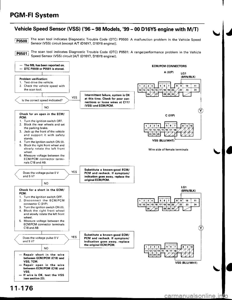
Vehicle Speed Sensor (VSSI ('96 - 98 Models,'99 - 00 D16Y5 engine with M/Tl
@The scan tool indicates Diagnostic Trouble Code (DTC) P0500: A malfunction problem in the Vehicle SpeedSensor (VSS) circuit Iexcept A!/T (D16Y7, D16Y8 engine)1.
The scan tool indicates Diagnostic Trouble Code (DTC) P0501: A range/performance problem in the VehicleSpeed Sensor (VSS) circuit [A,rT {D16Y7, D16Y8 engine)].
ECM/PCM CONNECTORS
A {32P} LG.t
VSS IBLU/WHT}
Wire side ot temale terminals
LGI(BRN/8LK}
The MIL has been reDorted on.DTC P0500 or P0501 is stored.
Problem verification:1- Test drive the vehicle.2. Check the vehicle speed withthe scan tool.
Intermittent tailure, system is OKat this time. Check tor Door con-nections or loose wires at C117{VSSland ECM/PCM.
ls the correct speed indicated?
Check for an open in the ECM/PCM:1. Turn the ignition switch OFF.2. Elock the rear wheels and setthe parking brake.3. Jack up the front of the vehicleand support it with safetystands.4. Turn the ignition switch ON (ll).
5. Block the right tront wheel andslowly rotate the left front
6, Measure voltage between theECM/PCM connector termi-nals C18 and A9.
Subslitute a known-good ECM/PCM and recheck. lf symptom/indic.tion goes away, replace theorisinal ECM/PCM.
Does the voltage pulse 0 Vand 5 V?
Check tor a short in ihe ECM/PCM:1. Turn the ignition switch OFF.2. Disco n n ect the ECM/PCMconnector C (31P).
3. Turn the ignition switch ON {ll).4. Block the right front wheeland slowly rotate the left front
5. Measure voltage between theECM/PCM connector terminalsC18 and A9.
Substitute a known-good ECM/PCM and recheck. lI symptom/indication goes away. replacethe original ECM/PCM.
Does the voltage pulse 0 Vand s V?
- Repair short in the wirebetwGen ECM/PCM {C18} endvss, TcM.- Repair open in the wirebetween ECM/PCM {Cl8} andvss.- lf wire is OK, test the VSSlsee section 23).
{BRN/BLK}
239l0lt
121611t8t9202321
2A2930
c {31P}
I38191o
tl12ialr5i6l10./
I2356a9l011
12l3l5t61tl8t920222a
27202930
12910
t2l13l.l7I l,/ 1,/231r.lslt., ),rlL
VSS {BLU/WHT}
11-176
Page 451 of 2189
PGM-FI System
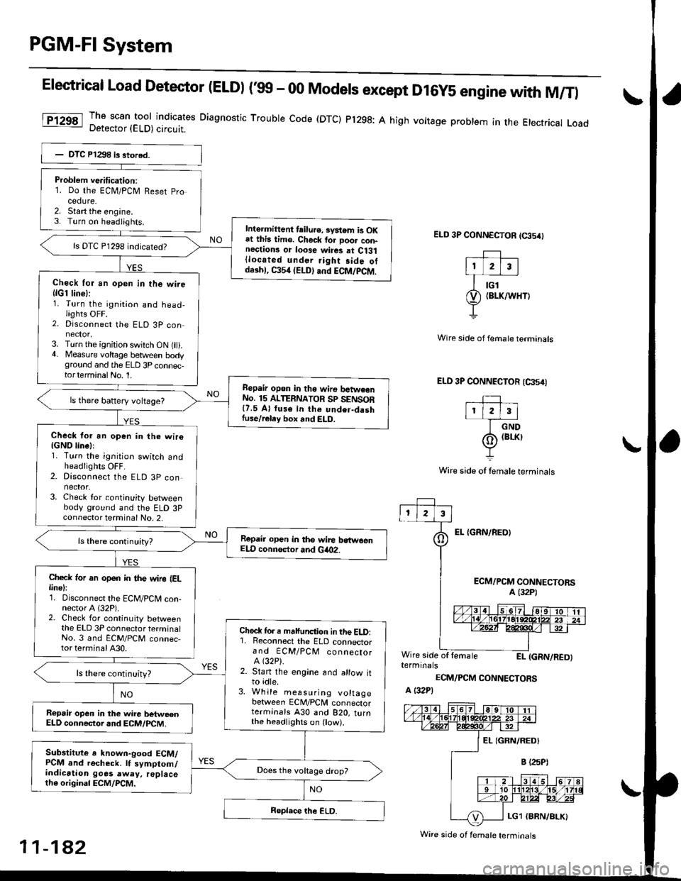
Elestrical Load Detector (ELDI ('99 - 00 Models except D16y5 engine with M/Tl
The scan tool indicates Diagnostic Trouble code (DTCI Pl298: A high vottage problem in the Etectrical LoadDetector (ELD) circuit.
ELD 3P CONNECTOR (65/0
EL {GRN/REOI
Wire side of fernale terminals
ELD 3P CONNECTOR (CA54I
TIr l2l3l
I crvo
(o) (BrKr
Y
Wire side of lemale terminals
ECM/PCM CONNECTORSA (32P1
Wire side of lemaleEI- IGRN/RED)terminals
ECM/PCM CONNECTORS
A {32P)
Problem ve.itication:1. Do the ECN4/PCM Reset pro
cedure.2. Start the engine.3- Turn on headiights.Inte.mittent teilu.e, svstem is OKat this lime. Chock for Door con-nections or loose wires at Ci31{located under Jight side otdaihl, C354 (ELD) and ECM/PCM.
ls DTC P1298 indicated?
Check for an open in the wire{lG1 line}:1. Turn the ignition and head-lights OFF.2. Disconnect the ELD 3P con
3. Turn the ignition switch ON (ll).4. Measure voltage between bodyground and the ELD 3P connec-torterminalNo. 1.
Repair opon in tho wiro batwe€nNo. 15 ALTERNATOR Sp SENSOR{7.5 A} fuse in th6 undor-dashIuse/reley box and ELD.
ls there battery voltage?
Check for an open in the wiro{GND linel:1. Turn the ignition switch andheadlights OFF.2. Disconnect the ELD 3P connector.3. Check for continuity betweenbody ground and the ELD 3Pconnector terminal No. 2,
Repair open in the wire bstwoenELD connsctor and Gia02.
Check ,or an open in the wire IELlinel:1. Disconnect the ECM/PCM con-nector A (32P).2. Check for continuity betweenthe ELD 3P connector terminalNo. 3 and ECM/PCM connec-tor terminal A30.
Chock fo. a malfunction in the ELD:'1. Reconnect the ELD connectorand ECM/PCM connectorA (32P).
2. Stan the engine and allow itto idle.3. While measuring voltagebetween ECM/PCM connectorterminals A30 and B2O, turnthe headlighrs on ow).
ls there continuity?
Repsir op€n in the wire betweenELD connector and ECM/PCM.
Substitute a known-good ECM/PCM and recheck. lf symptom/indication goes away. replacelh6 original ECM/PCM.
Does the vokage drop?
Wire side of f€male terminals
11-182
Page 525 of 2189

Emission Control System
Exhaust Gas Recirculation (EGR) System (D16Y5 engine with GWI (cont'dl
lTl49il T_he scan tool indicates Diagnostic Trouble Code (OTC) P1491: A malfunction in the Exhaust Gas Recirculation- lEgh) svstem.
CvT lM/T see page 1l-2611:
J
EGR VALVELIFT SENSOR#16 HOSE
PUMP/GAUGE,0- 30 in.HsA973X-041-XXXXX
EGRVALVE
The MIL has been reoorted on.DTC P1491 is stoled.
Problem verification:1. Do the ECM/PCM Reset Proce-du re.2. Connect the SCS service con'
3. Start the engine. Hold theengine at 3,000 rpm with noload {in Park or neutral) untilthe radiator fan comes on,4. Drive the vehicle on the roadfor approx. 10 minutes. Try tokeep the engine speed in the1,700 - 2,500 rpm range.
Intermittonl failure, system is OKat this time. Check for Door con-nections or loose wires at, C144{EGR velve} and ECM/PCM.
ls DTC P l49l indicated?
Check fo. vacuum to ihe EGR
1. Disconnect the No. 16 hose fromthe EGR valve.2. Connect a vacuum pump/gauge to the hose.3. Start the engine and let it idle.
ls there any vacuum?
Check tor a malfunction in theEGR control solenoid valve:'1. Disconnect the EGR controlsolenoid valve 2P connector,2. Becheck the No. 16 hose for
Check vacuum hose routing o,the entire EGR svstem. lf hoserouting is OK, replac€ the EGRcontrol solenoidvalv6.
ls there any vacuum?
Substitute a known-good ECM/PCM and recheck. It symptom/indicalion goes away, replacethe original ECM/PCM.
(To page 11 257)
11-256
Page 1234 of 2189
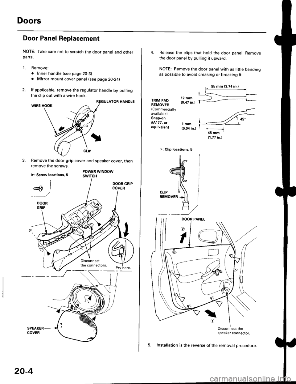
Doors
Door Panel Replacement
NOTE; Take care not to scratch the door panel and otherpans.
1. Remove:
. Inner handle (see page 20-3)
. Mirror mount cover panel (see page 20-24)
2. lf applicable, remove the regulator handle by pulling
HANOLE
3. Remove the door grip cover and speaker cover, thenremove the screws.
>: Screw locations, 5POWER WTNOOWswtTct{
the clip out with a wire hook.
20-4
4. Release the clips that hold the door panel. Remove
the door panel by pulling it upward.
NOTE: Remove the door panel with as little bending
as possible to avoid creasing or breaking it.
95 mm {3.74 in.)
.L12 mm(0.47 in.) fTRIM PADREMOVER(Commercially
availablelSnap-on#A'177, o.equivalenllmm(0.04 in.l
r_
rr-l
45 mm(1.77 in.l
>i Clip loc.tions, 5
lu-i
J$- I
:fe i
cL,P / IREMovERil I
_ _t/
Dasconnect the;peaker connector,
5. lnstallation is the reverse of the removal procedure.
Page 1246 of 2189
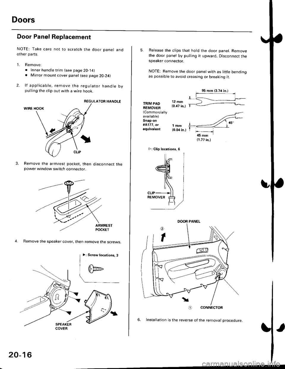
Doors
Door Panel Replacement
NOTE: Take care not to scratch the door panel andother pa rts.
'1. Remove:
. Inner handle trim (see page 20-14). Mirror mount cover panel (see page 20-24)
2. lf applicable, remove the regulator handle bypulling the clip out with a wire hook.
REGULATOR HANDLE
WIRE HOOK
Remove the armrest pocket, then disconnect thepower window switch connector.
ARMRESTPOCKET
4. Remove the speaker cover, then remove lhe screws.
3.
I
>: Screw locations, 3
| 6b:a,'
L"_
COVER
20-16
TRIM PADREMOVER(Commercially
available)Snap-on#A'177, orequivalent1mm{0.04 in.)
5. Release the clips that hold the door panel. Removethe door panel by pulling it upward. Disconnect thespeaker connector.
NOTE: Remove the door panel with as little bendingas possible to avoid creasing or breaking it.
.L12 fim(0.47 in.) T-
>: Clip locations,
l^
J[
=l$
ll,\*
atr-
,,)
REMoVER tl-)
11.77 in.l
O) CONNECTOR
6. lnstallation is the reverse of the removat oroceoure.
DOOR PANEL