Page 1374 of 2189

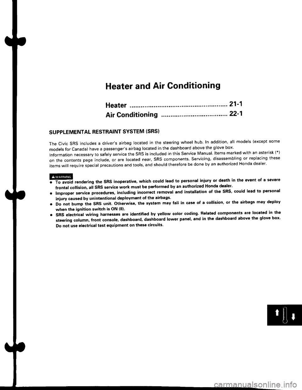
Heater and Air Conditioning
Heater '.'..""" 21'1
Air Conditioning ......."'.. "' 22-1
SUPPLEMENTAL RESTRAINT SYSTEM (SRS}
The civic sRs includes a driver's airbag located in the steering wheel hub ln addition, all models (except some
models for canada) have a passenger's airbag located in the dashboard above the glove box'
Information necessary to safely service the sRS is included in this service Manual ltems marked with an asterisk (*)
on the contents page include, or are located near, sRs components. servicing, disassembling or replacing these
items will require special precautions and tools, and should therefore be done by an authorized Honda dealer'
@-";;il rendsring the SRS inoperative, which could lead to personal iniury or deaih in the svent of a sev€re
frontal collision. all SRS service work must be pertormed by an authorized Honda d€aler'
. lmploper service procedures, including incorrest removal and instsllation of the sRs, could lead to personal
iniury caused by unintentional deployment of the airbags'
o Do not bump the SRS unit. Otherwise. the system may fait in case of a collision. or the airbags may deploy
when the ignition switch is ON {ll}'
. sRs electrical wiring harncsses are id€ntified by yellow colol coding. Related components ale located in lhe
steering column, front console, dashboard, dashboald lowet panel, and in the dashboard above the glove box'
Do not use electricaltest equipment on these circuits.
Page 1425 of 2189

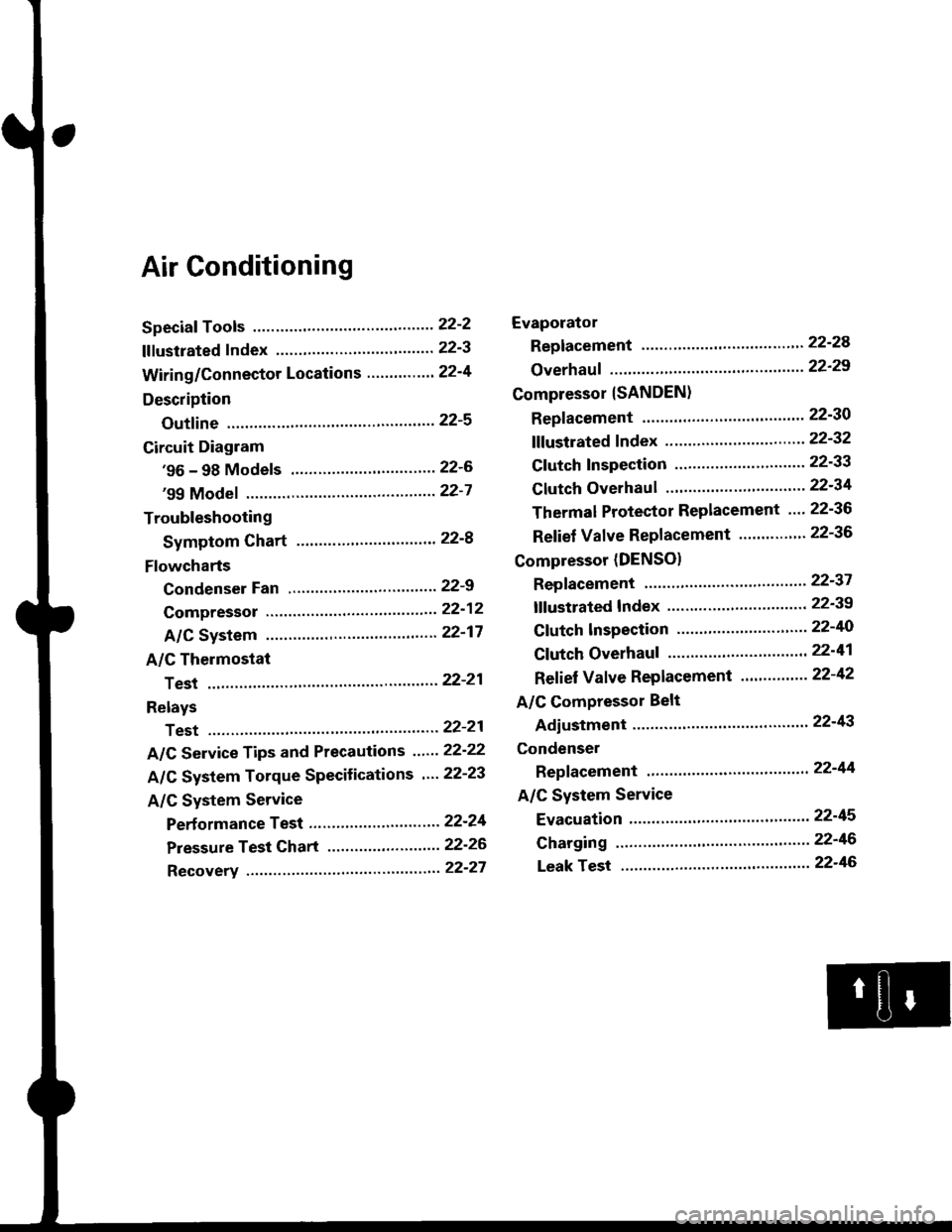
Air Conditioning
Speciaf Tools ......'.....' 22-2
f f f ustrated f ndex ......................... ".......' 22-3
Wiring/Connector Locations'.........'.... 22'4
Description
Outfine ............ .......22-s
Circuit Diagram
'96 - 98 Models ......"..........".......'.... 22-6
'99 Modef """""""' 22-7
Troubleshooting
Symptom Chart ".'......""................. 22-8
Flowcharts
Condenser Fan .........".................,..'. 22-9
Compressor .....""" 22-12
A/C System .........'.22'17
A/C Thermostat
Test ........'.......' """'22'21
Relays
Test ....."'......... ..""'22-21
A/C Service Tips and Precautions ......22-22
A/C System Torque Specifications '...22-23
A/C System Service
Performance Test ... '."......... ".... ....'..22-24
Pressure Test Chart .................. .... "' 22-26
Recovery ...".........," 22-27
Evaporator
Replacement .....",' 22'24
Overhauf .....-.....""' 22'29
Compressor {SANDEN}
Repf acement ......'.' 22-30
fffustrated fndex ......"..................'.... 22'32
Cf utch Inspection ......... "............ ...... 22-33
Clutch Overhau I ........................ ....... 22-34
Thermal Protector Replacement .... 22-36
Relief Valve Replacement ......'..."". 22-36
Compressor (DENSO)
Repfacement ..""',' 22-37
lf lustrated Index ............................... 22-39
Clutch lnspection ............."'...... "'.... 22-40
Cf utch Overhaul .....................'......... 22-41
Ref ief Valve Replacement'..'......"'.. 22-42
A/C Compressor Belt
Adiustment ............22'43
Condenser
Repfacement .......,,22'44
A/C System Service
Evacuation ...,,,.......22-45
Charging '..........--'..22'46
Leak rest """""""'22-46
Page 1426 of 2189
Special Tools
Bef. No. Tool NumberDescriptionQty I Page Reference
o
@
*07JGG - 00l0l0A
07sAz - 0010004
07947 - 6340300
07965 - 6920500
Belt Tension Gauge
Backprobe Set
Driver Attachment
Hub Assembly Gulde Attachment
1
'1
1
22-43
22-14,16
22-34
22-35' Included in the Belt Tension cauge Set, 07TGG-0010004.
a6r
L
3r
22-2
Page 1432 of 2189
Troubleshooting
Symptom Chart
NOTE:
. Any abnormality must be corrected before continuing the test.. Because of the precise measurements needed. use a multimeter when testinq.. Before performing any troubleshooting procedures check:- Fuses No. 47 l7 -5 Al, No. 56 (20 A) in the under-hood fuse/relay box, and No. 17 (7.5 A) in the under_dash fuse/relavbox- Grounds No. c401, c402, G751- Cleanliness and tightness of alt connectors
SymptomRemedy
Condenser fan does not run at all.Perform the procedures in the flowchart {see page 22-9).
Compressor clutch does not engage.Perform the procedures in the flowchart lsee page 22-12).
Ay'C system does not come on (compressor and fan),Perform the procedures in the flowchan (see page 22-17).
Both heater and A,/C do not work.. '96 - 98 models-Perform the procedures in the flowchart
{see page 21-18).. '99 - 00 models-Perform the procedures in the flowchart(see page 21-35).
22-8
Page 1433 of 2189
Condenser Fan
CONDENSER FAN RELAY 4P SOCKET
JUMPERwlRE
(cont'd)
22-9
Conden3er fan does not run at all.
Check the No. 56 (20 A) fuse in the
unde.hood frJse/relaY box, and the
No. 17 (7.5 A) fuse in the under-
dash fuse/relay box.
Reolace the fuse{s), and techeck
Remove the condenser lan rclaY'
and test it (see page 22 21i
Replace the condensei fan relav.
Check the under-hood tus6/relaY
Measure the vohage between the
No. 2 terminalofthe condenser fan
relav 4P socket and bodv ground.
ls there battery voltage?
Check the condenser lan Powersupply circuit:Connect the No. 1 and No. 2 teF
minals of the condenser fan relay
4P socket with a jumper wire
Does the condenser fan run?To page 22-10
Io page 22 11
Page 1434 of 2189
Troubleshooting
Condenser Fan (cont'd)
CONDENSER FAN RELAY 4P SOCKET
CONDENSEB FAN 2P CONNECTORWire side of female terminals
-=F_
l!.lI slx
@I
Check tor an opon in the wi.o:1. Disconnect the jumper wire.2. oisconnect the condenser tan2P connector.3. Check for continuity betweenthe No. 1 terminal of the con-denser fan relay 4P socket andthe No. 1 terminal of the con-denser fan 2P connector.
Rapair op6n in the wirs bgtwconthe condcnsor tan rclay and thecondgnlar fan.
ls there continuity?
Check to. en open in the wire:Check for continuity between theNo. 2 terminal ot the condenserfan 2P connector and bodyground.
Check Ior rn opon in th6 wirebctwoen the condcnser tan andbody ground, lf iho wirc ii OK,chcck for poor ground at G751.
ls there continuity?
Replaco the condense. fan motor.
22-10
Page 1436 of 2189
Troubleshooting
Compressor
COMPRESSOR CLUTCH RELAY.P SOCKET
JUMPERWIRE
check the No. 56 (20 A) fuse in theunder'hood fuse/relay box, and theNo. 17 (7.5 A) fuse in the under,dash fuse/relay box.
Replace the fussls), and .echeck.
Remove the compressor clutchrelay, and test it {see page 22 21).
Check th6 und€r-hood tu3e/reby
Measure the voltage between theNo. 2 terminal of the compressorclutch relay 4P socket and bodyground.
Check the compressor clutchpow€r supply circuit:Connect the No. 1 and No. 2 termi-nals of the compressor clutch relay4P socket with a jumper wire.
Does the compressor clutch click?fo page 22-13
To page 22 14
22-12
Page 1437 of 2189
Ftom page 22 12
Check to. an opon in tho wire:
1. Disconnect the jumper wire
2. Disconnect the comPressor
clutch 1P connector.
3. Check lor continuity between
the No. 1 terminal o{ the com_pressor clutch relaY 4P socket
and the terminal of the com-pressor clutch 1P connector'
Repeir open in the wiro between
the compressoa clutch relaY and
the comDres3or clulch.ls there continuity?
Inspect the comPre3sor clutch
clo.rance, lhe tharmal ProtgdorISANDENI, and tha compr6ssor
clutch field coil {SANDEN: Soepag. 22-33; DENSO: See Pag.22-10t.
COMPRESSOR CLUTCH RELAYiaP SOCKET
r--------t RED
L-r-]-_ll2l I--r- |l1l3l I
@
I
HI
1___J-RED
COMPRESSOR CLUTCH 1P CONNECTOR
Wire side of female terminals
(cont'd)
22-13