Page 970 of 2189

Start Clutch Control@
T
Start Clutch Calibration Procedure
NOTE: When the following parts are replaced, the TCM
must memorize the feedback signal for the start clutch
control.
. TCM
. Transmissionassembly
. Stan clutch assembly
. Lower valve bodv assembly
. Engine assembly or overhaul
'96 Model Only
CAUTION: Do not uso this procsdure on'97 - (X) mod-
els or you will damage the transmission. On '97 - 00
models, the TCM or PCM memorizes ths loodback sig'
nals when you drive the vehicle.
1. Engage the parking brake, and block the front
wheels securely.
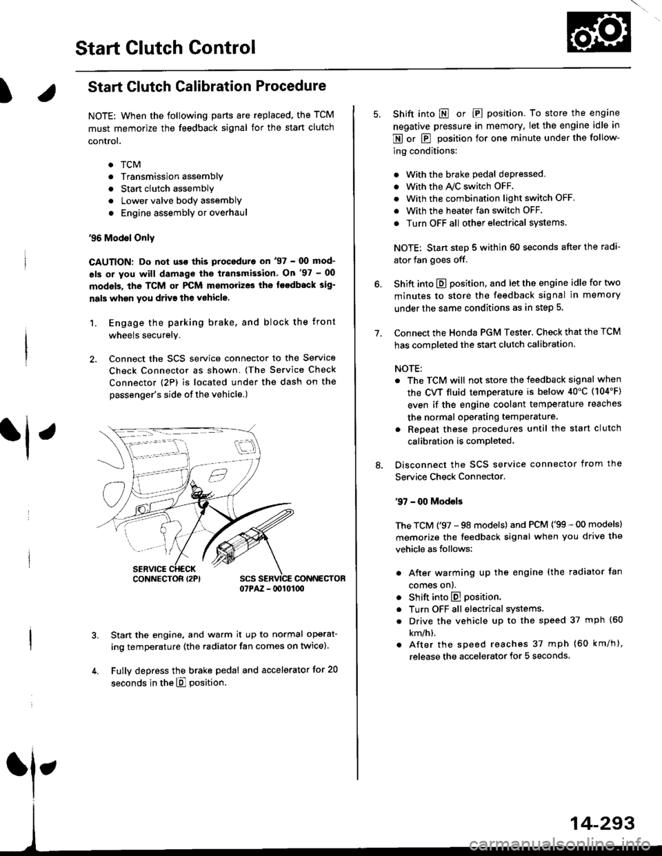
2. Connect the SCS service connector to the Service
Check Connector as shown. (The Service Check
connector (2P) is located under the dash on the
passenger's side of the vehicle.)
CONNECTOR07PAZ - lDl01(xt
Start the engine, and warm it up to normal operat-
ing temperature (the radiator fan comes on twice).
Fully depress the brake pedal and accelerator for 20
seconds in the E] position.
rl ,
CONNECTOR I2PI
14-293
7.
Shift into E o|. E position. To store the engine
negative pressure in memory. Iet the engine idle in
E or E position for one minute under the follow-
ing conditions:
. With the brake pedal depressed,
. with the y'\/c switch oFF.
. With the combination light switch OFF.
. With the heater fan switch OFF.
. Turn OFF all other electrical systems
NOTE: Start step 5 within 60 seconds after the radi-
ator fan goes off.
Shift into E position, and let the engine idle for two
minutes to store the feedback signal in memory
under the same conditions as in step 5.
Connect the Honda PGM Tester. Check that the TCM
has completed the start clutch calibration.
NOTE:
. The TCM will not store the feedback signal when
the CVT fluid temperature is below 40"C (104'F)
even if the engine coolant temperature reaches
the normal operating temperature.
. Repeat these procedures until the start clutch
calibration is completed-
Disconnect the SCS service connector from the
Service Check Connector.
'97 - 00 Models
The TCM ('97 - 98 models) and PCM ('99 - 00 models)
memorize the feedback signal when you drive the
vehicle as follows:
. After warming up the engine (the radiator fan
comes onl.
. Shift into E position.
. Turn OFF all electrical systems,
. Drive the vehicle up to the speed 37 mph (60
km/h).
. After the speed reaches 37 mph (60 km/h),
release the accelerator for 5 seconds.
Page 979 of 2189

Lower Valve Body Assembly
Replacement
@ Make sure lifts, iacks, and saf€ty stands
are placsd prop€rly {sea section 1).
CAUTION: While removing and installing th6 lower
valve body asssmbly, b€ sule not to allow dust and
other for€ign particles to entsr inio the transmksion.
1. Raise the front of the vehicle, and support it with
safetv stands (see section 1).
2. Set the parking brake, and block both rear wheels
securetv.
4.
6.
Remove the drain plug, and drain the CVT fluid.
Reinstall the drain plug with a new sealing washer(see page 1+299).
CAUTION: Keop all of other toreign parliclos out of
the transmission.
Disconnect the 8P connector from the solenoid har-
ness connector.
Remove the ATF cooler hoses at the ATF cooler
lines. Turn the ends of the ATF cooler hoses up to
prevent ATF from flowing out, then plug the ATF
cooler noses.
CAUTION: Keep all of other foroign particlo3 out of
tho transmission.
Remove the right front mounvbracket.
10 x 1.25 mmila N.m (,1.5 kgf.m, 33 lbtft)
RIGHT FRONTMOUNT/BRACKET
ATF COOLER LINE
10 x 1.25 mmsil N.m 15.5 kgf.m,40 rbr.ft)
ATF COOLER HOSE
14-302
14.
7. Remove the ATF cooler outlet line.
8. Remove the ATF cooler line bracket bolt.
9. Remove the ATF pan (fourteen bolts).
10. Remove the ATF strainer (two bolts).
1 l. Remove the one bolt securing the solenoid harness
connector,
12. Remove the
bolts).
lower valve body assembly (eight
LINE BOLT28 N.m (2.9 kgtm,21 lbtft)SEALINGReplace.
ATF COOI.-EROUTLET
OOWEL PIN
O.RINGFeplace.
SOLENOIO HARNESSCONNECTOR
5x1.0mm12 N.m 11.2 kgt.m,8.7 tbt.ftlO.RINGReplace.ATFSTNAINER
6x1.0mm12 N.m 11.2 kgt m,E.7 tbt'ft)
OOWEL NN
BODY ASSEMBLY
6x1.0mm12 N.m 11.2 kgf.m,8.7 rbf.ft)
ATF PAN GASKETReplace.
VALVE
ATF COOLER INLETUNE BRACKET BOLT8 x 1,25 mm26 N.m {2.7 kgf.m,20 tbf.frl
13.
ATF PANx 1.0 mm12 N.m 11.2 kgf.m, E.7 lbf.ftl
Install the new lower valve bodv in the reverse
ordgr of the removal orocedure.
CAUTION: Koep all ot other fo.oign particles out of
ths transmission.
NOTE:
. Replace the following parts:
- O-rings on the solenoid harness connector
and the ATF strainer- ATF pan gasket- Sealing washers
. lf the ATF cooler inlet line bracket is bent or
warped, put it back to the original position.
Perform the start clutch calibration orocedure on
page 14-293.
Page 991 of 2189
Transmission Housing/Lower Valve Body Assembty
Removal
NOTE:
. Clean all parts thoroughly in solvent or carburetor cleaner, and dry with compressed air.. Blow out all passages.
. When removing the lower valve body, replace the followingl- O-rings- ATF pan gasket- Sealing washers
DOWEL PIN
ATF STRAINER
6 x 1.0 mm BOLT
ATF PAN GASKETReplace.
ATF COOLER INLET LINEBRACKET BOLT8 x 1.25 mm
ATF COOI..ER INLET LINE
O.RINGReplace.
SOLENOIO HARNESS CONNECTOR
6 x'1.0 mm BOLT
LOWER VALVE BODY ASSEMBLY
6 x 1.0 mm BOLT
14-314
6 x 1.0 mm EOLT
Page 993 of 2189
Transmission Housing/Flywheel Housing
Removal
NOTE:
. Cleanall parts thoroughly in solvent or carburetor cleaner, and dry with compressed air.. Blow out all passages.
. When removing the transmission housing/flywheel housing, replace the following:- O-rings- Secondary drive gear assembly- Sta rt clutch assemblv- Flywheel housing gasket
ATF PASSAGE LINEHOLD€R ASSEMBLY
IX)WEL PIN
OIFFERENTIAL ASSEMBLY
SNAP RING
COTTER RETAINER
COTTERS, 25.5 mmSelective part
8 x 125 mm BOLT
O.RINGRsplaco.
VWHEEL HOUSING
EYWIIEEL HOUSING GASKETRoolace.
START CLUTCHASSEMBLYReplace.
ATF PA$gAGEUNE ASSEMBLY
6 x 1,0 mm BOLT
O.RINGReplace.
ATF PUMP DRIVE CHAIN
SNAP RING
THRUST SHIM,25x35mmSeloctive part
SECONDARYGEAR SHAFT
SECONDARY DRIVEGEAR ASSEMBLYReplace.
PARKPAWL SHAFT
THRUST SHIM, 22 r 28 mmSeloctive partGRII{GSReplac€.6 x 1.0 mm BOIT
ATF PUMP DRIVESPROCKET
PfTOT FLANGE
ATF PUMP DRTVESPROC|(ET HUB
THRUST WASHERS
PARK PAWLSPRING
INPUT SHAFT
14-316
DRIVEN PULLEY SHAFT
InANSMISS|O]{ HOUSTNG
Page 995 of 2189
End Cover/lntermediate Housing
Removal
NOTE:
. Cleanall parts in solvent or carburetor cleansr, and drywith compressed air,. Blow out all passages.
. When removing the end cover/intermediate housing, replacs the following parts:- O-rings- End cover gasket- Transmission housing gasket- Sealing rings- Sealing washers
8 x 1 .25 mm BOLT
REVERSE BRAKE
{u
END PLATE
6 x 1.0 mm BOLT
Dtsc
PLATE
DISC SPRING
SNAP
THRUST
END COVERGASXETFeplac€.25x31 mmSelective part
RING GEAR
THRUST WASHER
THRUSI NEEDLEBEARING
THRUST WASHER
CARRIER ASSEMBLY
THRUST WASHER
THRUST NEEDLEBEARING
SUN GEAR
INPUT SHAFT
SNAP RING
CLUTCH ENDPLATE
sNAP /R|NG I
8 x 1.25 mm BOLT
TRANSMISSTONHOUSING GASKETReplace.
DOWEL PIN
INIERMEDIATEHOUSING ASSEMSLY
FORWARD CLUTCHASSEMBLY
SEALING RING (RUBBER}
Replace.
SNAP RING
o.BINGReplace.
SNAP RINGRETAINER
SPRING RETAINER/RETURN SPRINGS
14-318
HOUSING
Page 997 of 2189
Manual Valve Body
Disassembly/lnspection/Reassembly
NOTE:
. Clean all parts thoroughly in solvent or carburetor cleaner, and dry with compressed air. Elow out all passages.. Coat all parts with CVT Fluid during assembly.
SPRING SEATREVERSE INHIBITORVALVE SPRING
REVERSE INHIBITORVALVE
MANUAL VALVE
MANUAL VALVE BODYInspect for wear, scratchesand sconng,
14-320
Page 1001 of 2189
Forward Glutch
Reassembly
NOTE:
. Clean all parts thoroughly in solvent or carburetor
cleaner, and dry them with compressed air.
. Blow out all passages.
. Lubricate all parts with CW Fluid before reassembly.
1. Inspect the check valve; if it's loose, replace the pis-
ton.
CHECK VALVE
Install new O-rings on the clutch pision.
PISTON
14-324
3. Install the piston in the clutch drum. Apply pressure
and rotate to ensure proper seatang,
NOTE: Lubricate the piston O-ring with CVT Fluid
before installing.
CAUTION: Do not pinch thc O-ring by installing the
pistoo with too much torqo.
CLUTCH DRUM
Install the return spring and spring retainer, and
position the snap ring on the retainer.
CLUTCH DRUM
Page 1014 of 2189

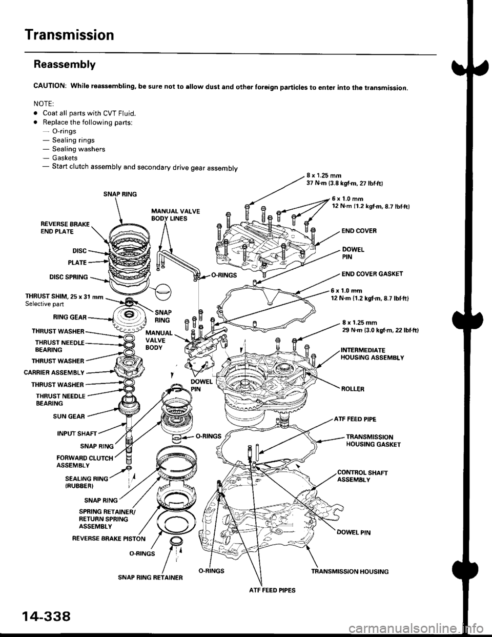
Transmission
Reassembly
CAUTION: While reassembling. be sure not to sllow dust and othor foreign particles to enter into the transmission.
NOTE:
. Coat all parts with CVT Fluid.
. Replace the following parts:- O-rings- Sealing rings- Sealing washers- Gaskets- Start clutch assembly and secondary drive gear assembly8 x 1.25 mm37 N.m {3.8 kgf.m,27 lbtftl
MANUAL VALVE
6x1.0mm12 N m 11.2 kgf.m,8.7 lbl.ft)
LINESREVERSE BRAKEEND PLATE
Dtsc
PLATE
DISC SPRING
THRUST WASHER
CARRIER ASSEMBLY
THRUST WASHER
THRUST NEEDLEBEARING
END COVEB
DOWELPIN
END COVER GASKET
6x1.0mm12 N.m 11.2 kgtm,8.7 lbtft)THRUST SHIM,25 x 31 mmSelective part
RING GEAR
THRUST WASHER
THRUSTBEARING
8 x 1.25 mm29 N.m 13.0 kgl m, 22 lbtftl
INTERMEDIATEHOUSING ASSEMBLY
ROLI.IR
SNAPRINGeBH^cMANUALVALVEBOOY
SUN GEAR
INPUT SHAFT
(RUBEERI
ATF FEED PIPE
O-RINGSTRANSMISSIONHOUSING GASKETSNAP RING
FORWARD CLUTCH
SNAP RING
SHAFTASSEMALY
DOWEL PtN
SPRING RETAINER/RETURN SPRINGASSEMBLY
REVERSE BRAKE PISTON
O.RINGS
SNAP RING
ATF FEED PIPES
14-338
SNAP RING RETAINERTRANSMISSION HOUSING