Page 1236 of 2189
Doors
Latch Replacement
NOTE: Baise the glass fully.
1. Remove:
. Door panel (see page 20-4)
. Plastic cover (see page 20-2). Outer handle (see page 20-5)
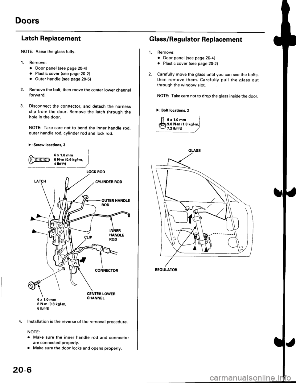
Remove the bolt, then move the center lower channel
forwa rd.
Disconnect the connector, and detach the harness
clip from the door. Bemove the latch through the
hole in the door.
NOTE: Take care not to bend the inner handle rod,
outer handle rod, cylinder rod and lock rod.
>: Screw locations, 3
6 x 't.0 mm8 N.m (0.8 kgt m,6 tbf.ftl
4. Installation is the reverse of the removal procedure.
NOTE:
. Make sure the inner handle rod and connector
are connected properly.
. Make sure the door locks and opens properly.
LOCK ROO
20-6
'1.
Glass/Regulator Replacement
Removel
o Door panel (see page 20-4)
. Plastic cover (see page 20-2l,
Carefully move the glass until you can see the bolts,
then remove them. Carefully pull the glass out
through the window slot.
NOTE: Take care not to drop the glass inside the door.
>i Bolt loc.tions,2
fi s'r.o-. iClb9.8 N.m 11.0 kst m,l
_-l't!!t ,/
GLASS
REGULATOR
Page 1241 of 2189
tOuter Handle Replacement
NOTE: Raise the glass fullY.
1. Remove:
. Door panel
. Plastic cover (see page 20-8)
2. Remove the screws.
>: Screw locations, 3
6x1.0mm6 N.m {0.6 kgf m,4 tbf.ftl
a\
3. Move the latch down, and remove the bolts.
>: Bolt locations,2
6x1.0mm9.8 N,m )11.O kst.n,7.2lbiftl //
4. Pull out the outer handle. Pry the outer handle rod
out of its joint using diagonal cutters.
NOTE:
. To ease reassembly, note location O of the outer
handle rod on the joint before disconnecting it.
. Take care not to bend the outer handle rod.
. Use a shop towel to protect the opening in the
door.
BUSHINGReplace.
OUTERHANDLEROD
5.
o
DIAGONAL \
:"'* ,w,
lnstallation is the reverse of the removal procedure
NOTE: N4ake sure the door locks and opens properly.
SHOP TOWEL
20-11
Page 1243 of 2189
t}
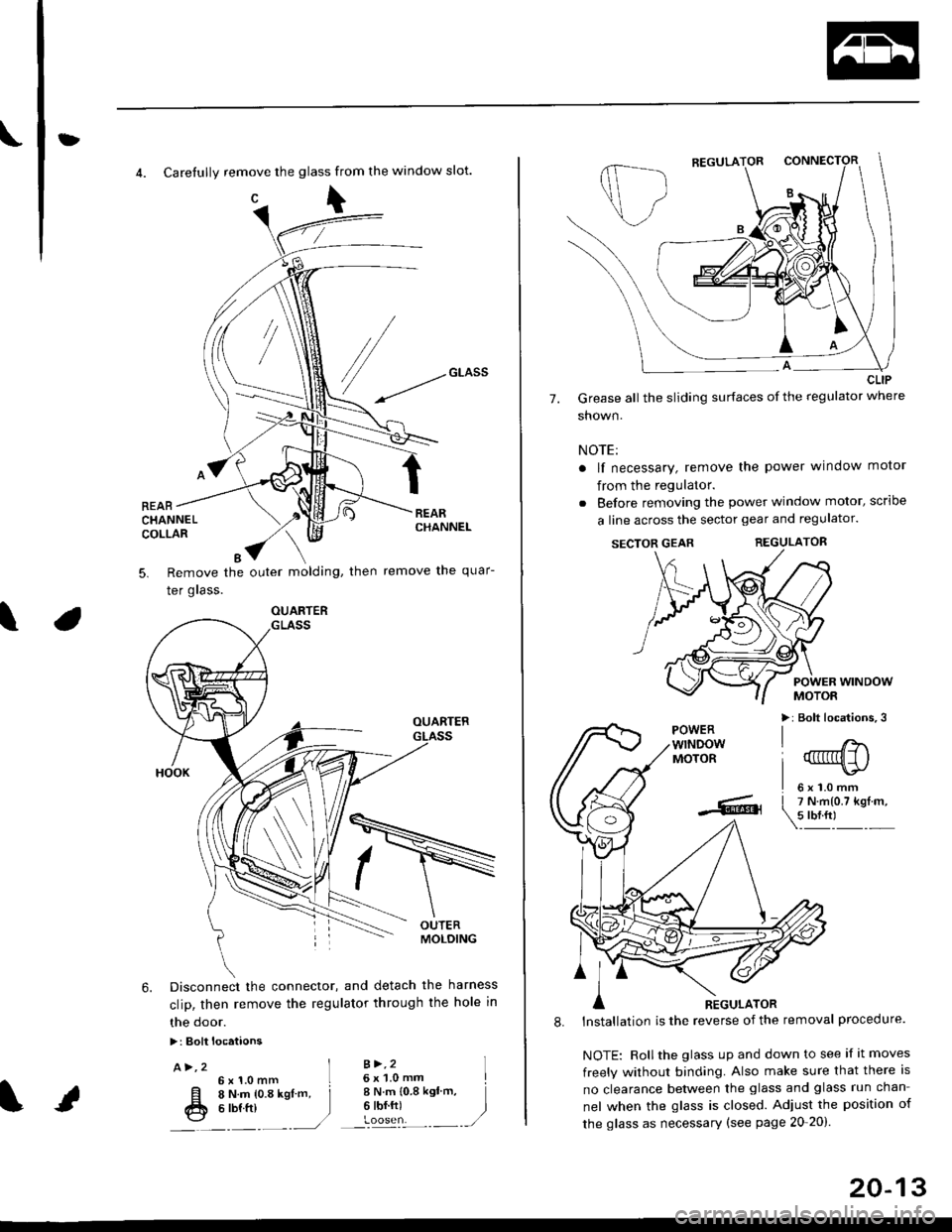
4. Carefully remove the glass from the window slot.
c\
REARCHANNELCOLLAR
Remove the outer molding, then
Ier grass.
remove the quar-5.
\
6. Disconnect the connector, and detach the harness
clip, then remove the regulator through the hole in
the door.
>: Bolt locataons
A>,2 ]6x1.0mm L
[l o t't.- to.a rsl -. j
fr e ttt ttt )---�.---.-,/
B >,26 x 'l.0 mmI N.m {0.8 ksl'm,6 tbf.ft)
I
)
OUARTER
20-13
7.
CLIP
Grease all the sliding surfaces of the regulator where
shown.
NOTE:
a lf necessary, remove the power window motor
from the regulator.
. Before removing the power window motor, scrloe
a line across the sector gear and regulator.
SECTOR GEARREGULATOR
POWER WINDOWMOTOR
>: Bolt locations,3POWERwTNDOWMOTOR
l'
-... er
A nicuuron
8. lnstallation is the reverse of the removal procedure.
NOTE: Rollthe glass up and down to see if it moves
freely without binding. Also make sure that there is
no clearance between the glass and glass run chan-
nel when the glass is closed. Adjust the position of
the glass as necessary (see page 20-20).
Page 1247 of 2189
bOuter Handle Replacement
NOTE: Raise the glass fully.
1. Remove:
. Door panel
. Plastic cover (see page 20-14)
2. Pull out the retainer clip.
3.e\
CYLINOER PROTECTOR
LOCK CYLINDER
RETAINERCLIP
Remove the bolts, then remove the cylinder protec-
tor, lock cylinder and outer handle.
>: Bolt locations,2
6x1.omm ]9.8 N.m {1.0 kgf.m,1.2tbl,ttl )_, _-_-,/
CYLINDERPROTECTOR
LOCK CYLINOER
CYLINOER ROD
20-17
4. Pull out the outer handle. Pry the outer handle rod
out of its joint using diagonal cutters.
NOTE:
. To ease reassembly, note location @ ot the outer
handle rod on the joint before disconnecting it.
. Take care not to bend the outer handle rod.
. Use a shop towel to protect the opening in the
door.
DIAGONALCUTTERS
SHOPTOWEL
5. Installation is the reverse of the removal procedure.
NOTE: Make sure the door locks and opens properly.
EUSHINGReplace.
\
,pr,
Page 1250 of 2189
Doors
Glass/Regulator Replacement (cont'dl
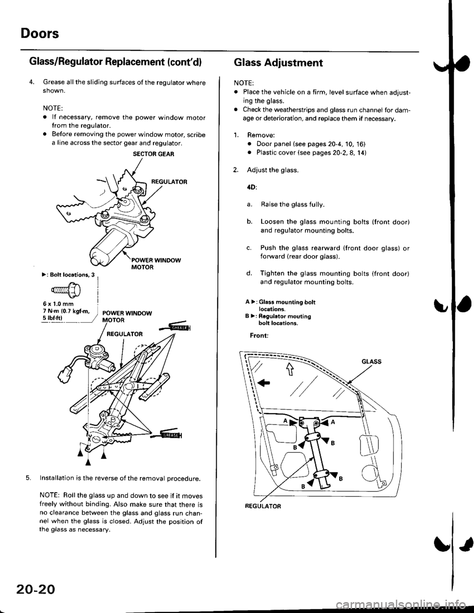
Grease all the sliding surfaces of the regulator where
shown.
NOTE:
. lf necessary, remove the power window motorfrom the regulator.
. Before removing the power window motor, scribe
a line across the sector gear and regulator.
REGULATOR
5. Installation is the reverse of the removal orocedure.
NOTE: Roll the glass up and down to see if it moves
freely without binding. Also make sure that there isno clearance between the glass and glass run chan-nel when the glass is closed. Adjust the position ofthe glass as necessary.
SECTOR GEAR
20-20
Glass Adjustment
NOTE:
. Place the vehicle on a firm, level surface when adjust-
ing the glass.
. Check the weatherstrips and glass run channel for dam-
age or deterioration, and replace them if necessary.
1. Remove:
. Door panel (see pages 20-4, 10, 16). Plastic cover (see pages 20-2,8, 14)
2. Adjust the glass.
4D:
Raise the glass fully.
Loosen the glass mounting bolts (front door)
and regulator mounting bolts.
Push the glass rearward (front door glass) or
iorward (rear door glass).
Tighten the glass mounting bolts (front door)
and regulator mounting bolts.
A >: Gl.3s mounting boltlocations.B >: Regulrtor moutingbolt loc.tions.
Front:
a.
b.
d.
REGULATOR
Page 1252 of 2189
Doors
Glass Adjustment {cont'd)
c. Tighten the roller guide bolts.
d. Loosen the front channel bolts.
e. Lower the glass.
f. Push the front channel against the glass, then
tighten the mounting bolts.
MOUNTINGBOLT
3. Check that the glass moves smoothly.
4. Raise the glass fully and check for gaps.
5. Check the glass operation.
NOTE: Check that the glass contacts the glass run
channel evenly.
WEATHERSTRIP
GLASS
U
-\,
20-22
6. Check for water leaks.
Spray water over the roof and on the sealing area
as shown.
NOTE:
. Adjust the water pressure as shown.
. Do not squeeze the tip of the hose.
0.5 m {1.6ft)
HOSE
Attach the plastic cover, then install the door panel
(see pages 20 4, 10, 16).
Install the regulator handle so it points forward and
up at a 45 degree angle with the glass closed.
Forward -
1.
HOSE
300 mm {11.8 in)
Page 1253 of 2189
bPosition Adjustment
NOTE: Place the vehicle on a firm, level surface when
adjusting the doors.
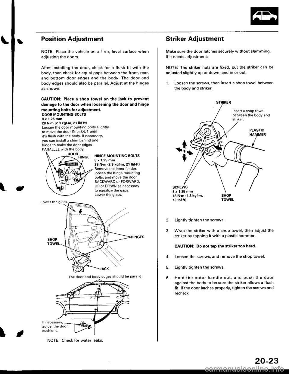
After installing the door, check for a flush fit with the
body, then check for equal gaps between the front, rear,
and bottom door edges and the body. The door and
body edges should also be parallel. Adjust at the hinges
as shown,
CAUTION: Place a shop towel on the iack to prevent
damage to the door when loosening the door and hinge
mounting bohs for adiustment.
DOOR MOUNTING BOLTS8 x 1.25 mm28 N.m {2.9 kgf.m.21 lbt'ft}Loosen the door mounting bolts slightly
to move the door lN or OUT until
it's flush with the body. lf necessary,
vou can installa shim behind one
hinge to make the door edgesPARALLEL with the body.
J
HINGE MOUNTING BOLTSI x 1.25 mm28 N.m (2.9 kgf.m,21 lbtft)Remove the inner fender,loosen the hinge mountingbolts, and move the doorBACKWARD or FORWARD,UP or DOWN as necessaryto equalize the gaps.Lower the glass.
\
The door and body edges should be parallel-
ifF t
NOTE: Check for water leaks.
20-23
Striker Adjustment
lvlake sure the door latches securely without slamming.
lf it needs adjustment:
NOTE; The striker nuts are fixed, but the striker can be
adjusted slightly up or down, and in or out.
'L Loosen the screws, then insert a shop towel between
the body and striker.
Insert a shop towelbetween the body and
sc8Ews8 x 1.25 mm18 N.m (1.8 kgf.m,13 tbtftl
PLASTIC
2. Lightly tighten the screws.
3. Wrap the striker with a shop towel, then adjust the
striker by tapping it with a plastic hammer.
CAUTION: Do not tap the striker too hard.
4. Loosen the screws. and remove the shop towel.
Lightly tighten the screws.
Hold the outer handle out, and push the door
against the body to be sure the striker allows a flush
fit. lf the door latches properly, tighten the screws and
recheck.
5.
Page 1258 of 2189
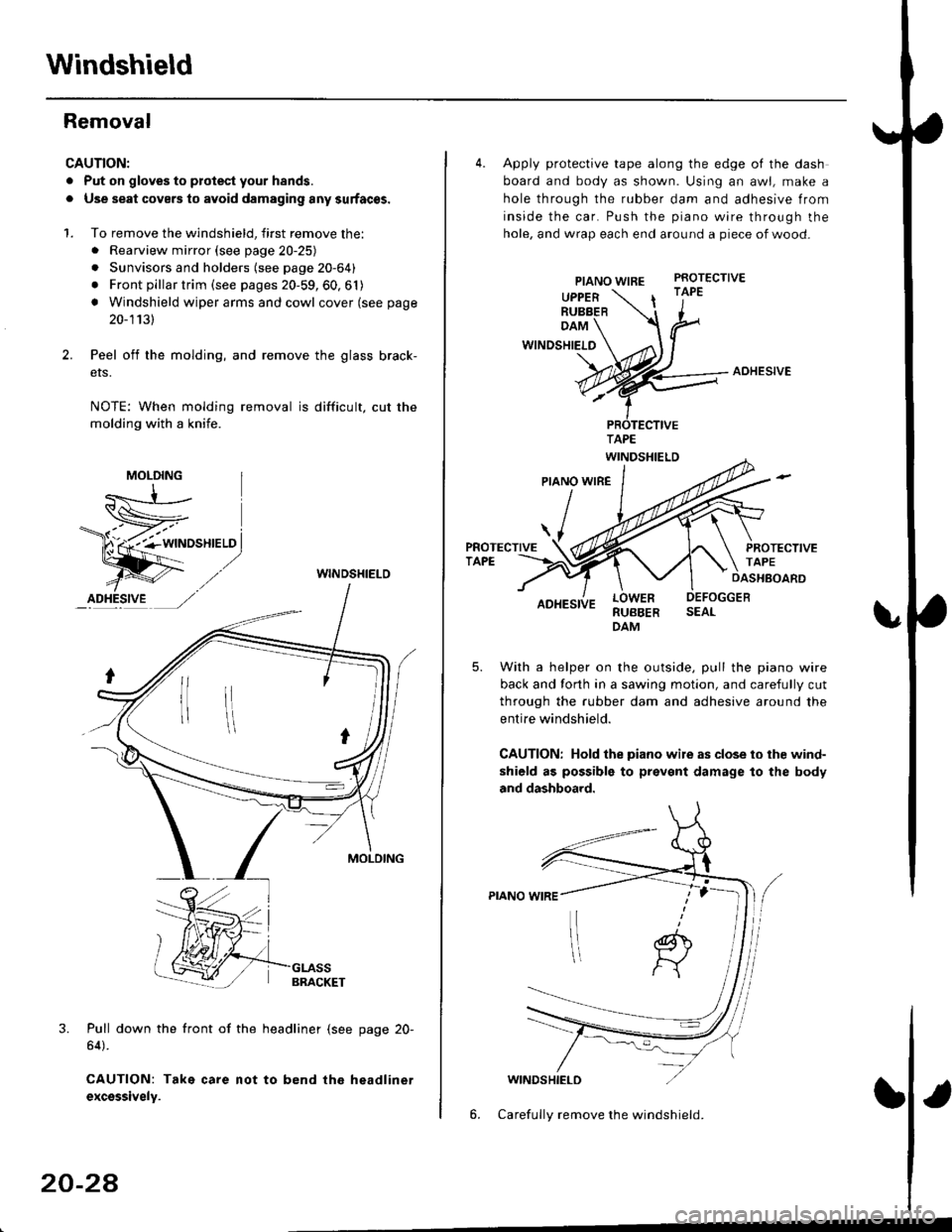
Windshield
Removal
CAUTION:
. Put on gloves to plotest your h8nds.
. Use seat covers to avoid damaging any surfaces.
1. To remove the windshield, first remove the:. Rearview mirror (see page 20-25)
. Sunvisors and holders (see page 20-64)
. Front pillar trim (see pages 20-59, 60, 61)
! Windshield wiper arms and cowl cover (see page
20-1131
Peel off the molding, and remove the glass brack-
ers.
NOTE: When molding removal is difficult, cut the
molding with a knife.
WINDSHIELO
3. Pull down the front of the headliner (see page 20-
64).
CAUTION: Take care not to bend the headlinet
excsssively.
MOLDING
20-24
4. Apply protective tape along the edge of the dash
board and body as shown. Using an awl, make a
hole through the rubber dam and adhesive from
inside the car. Push the piano wire through the
hole, and wrap each end around a piece of wood-
PIANO WIREPROTECTIVE
UPPERRUBBER| '1"
DAM
WINDSHIELO
AOHESIVE
RUBBERDAM
With a helper on the outside, pull the piano wire
back and forth in a sawing motion, and carefully cut
through the rubber dam and adhesive around the
entire windshield.
CAUTION: Hold the piano wile as close to ihe wind-
shield as possible to prevent damage to the body
and dashboard.
WINDSHIELD
6. Carefully remove the windshield.