Page 102 of 2189
Engine Removal/lnstallation
Removal(cont'dl
29. Remove the Ay'C compressor.
NOTE: Do not disconnect the Ay'C hoses.
30.
8x 1.25 mm A/C COMPRESSOR24 N.m (2.{ kgf.m, t7 tbtft}
Remove the shift cable (IVT).
NOTE:
. Take care not to bend the cable when removingit. Always replace any kinked cable with a newone.
. Adjust the shift cable when installing (see sec_tion 14).
8 x 1.25 mm22 N.m (2.2 kgf.m, 16 lbf.frl
LOCK WASHERBeplace.6x1.0mm14 N.m (1.4 kgf.m, tO tbtft)
5-8
A/C COMPRESSOR
t
{
31. Remove exhaust pipe A.
Dl6Y5. D16Y7 engines:
8 x 1.25 mm22 N.m 12.2 ksl.m. 16 tbI.fr)Replace.
SELF.LOCKING8 x 1.25 mm16 N.m (1.6 kgtm,12 tbt.ftlReplace.
D16Y8 ongin6;
8 x 1.25 mm22 N.m (2.2 kgf.m. 16 tbf.ftlReplace.
GASKETReplace.
SELF.LOCKING NUT10 x 1.25 mm33 N.m {3.4 kgt.m,25 lbr'frlReplace.
SELF.LOCKING NUT8 x 1.25 mm16 N.m 11.6 kgf.m, 12 lbtft)Replace.
SELF-LOCKING NUTl0 x 1.25 mm54 N.m (5.5 kgf.m, 40 lbf.ft)Replace.
Page 106 of 2189
Engine RemovaUlnstallation
Installation
Brackei Bolts Torque Specifications:
Dl5Y5, Dl6Y7, Dl6Y8 €nginss
D16Y5, D16Y8 engines (M/Tl:
REAR STIFFENER
8 x 1.25 mm2/t N.m 12.4 kgf.m, 17 tbf.ftl
EXCEPT D16Y5, Dl6Yg engines lM/T)jSTIFFENERTighten the bolts on the stiffenerin the numbered sequence as shown
10 x 1.25 mm44 N.m 14.5 kgf.m,33 tbf.frt
O8x1.25mm24 N.m {2.4 kg{.m,17 tbr.ftt
10 x 1.25 mm14 N.m 14.5 kgt m,33 tbf.ft)
10 x 1.25 mm44 N.m {4.5 kgt m,33 tbr.ftl
10 x 1.25 mm54 N.m {5.5 kgf.m,40 rbf.ftl
10 x 1.25 mm44 N.m {4.5 kg'f.m,33 tbtftlALTERNATOFBRACKET
li) o).
l3l 10 x 1.25 mm44 N.m {1.5 kgt.m,33 tbt.ft)8 x 1.25 mm24 N.m (2.4 kgf.m,17 tbf.ft)
o16Ys, D16Y8enginoslM/T):FRONTSTIFFENER
10 x 1.25 mm4,4 N.m {4.5 kg{.m.33 tbf.ftl8 x 1.25 mm2{ N.m (2.t kgtm,17 rbtft)
10 x 1.25 mm14 N.m (4.5 kgf.m,33 lbf.ftl
5-12
Page 112 of 2189

Cylinder Head/Valve Train
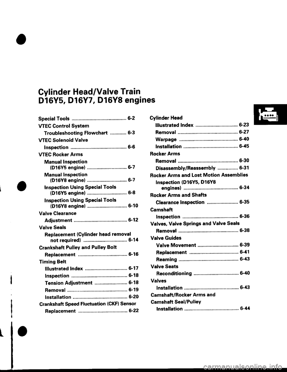
Dl6Y5, D16Y7, Dl6Y8 engines
Special Tools ............. G2
VTEC Control System
Troubleshooting Flowchart .........." 6-3
VTEG Solenoid Valve
Inspection ............" 6-6
VTEC Rocker Arms
Manual lnspection
(D16Y5 engine) ............................. 6-7
Manual Inspection
(D16Yg enginel ................'............ 6-7
Inspection Using Special Tools
{D16Y5 engine} .....................""'... 6-8
Inspection Using Special Tools
(D16Y8 engine) .........................'.'. 6-10
Valve Clearance
Adiustment ..."".....6-12
Valve Seals
Replacement (Cylinder head removal
not requiredl ................................ 6-1tl
Crankshaft Pulley and PulleY Bolt
Replacement ."...... &16
Timing Selt
lllustrated Index ............................... 6-17
Inspection .............. 6-18
Tension Adjustment ........................ 6- 1 I
Removal ......,,......... 6-19
lnstallation ............. 6-20
Crankshaft Speed Fluctuation (CKF) Sensor
Repf acement .........6'22
Cylinder Head
lllustrated Index ............................... 6-23
Removal ................. 6-27
Warpage ................ 6-40
lnstallation ............. 6-45
Rocker Arms
Removal ................. 6-30
Disassembly/Reassambly ............... 6-31
Rocker Arms and Lost Motion Assemblies
Inspection (D16Y5, D16Yg
enginesl "..........' 5-34
Rocker Arms and Shafts
Glearance Inspection ....................... 6-35
Camshaft
Inspection .............. 6-36
Valves, Valve Springs and Valve Seals
Removal ........""..... 6-38
Valve Guides
Valve Movement .............................. 6-39
Replacement .........6-41
Reaming .......'......'.' 6-43
Valve Seats
Reconditioning .'....6'40
Valves
lnstallation ............. 6-tt3
Camshaft/Rocker Arms and
Camshaft Seal/Pulley
lnstallation ............. 6-44
Page 114 of 2189

VTEC Control System
Troubleshooting Flowchart
tFtrsrl #ilH:::lj1t:"J:T,?ffnostic
rrouble code (Drc) Pr25e: A probrem in the vrEc Pressure switch circuit or
Reter to page 1 l-38 th roug h 1 1-55 before trou bleshooting.
* Road Test:Accelerate in 1st gear to an engine speed over 3,000 rpm(D16Y5 engine) or 6,000 rpm (D'16Y8 engine).Hold that engine speed for at least two seconds.It DTC P1259 is not repeated during the first road test, repeatthis test two more tames.
VTEC PRESSURE SWITCH 2PCONNECTOR
Terminal side ofmale terminals
Wire sid6 ol femalerermtnats
VTM
l1 (BLu/BLK)
f;-) |I
I
Y
I
The MIL has been reoorted on.DTC P1259 is sto.ed.
Check the VTEC Cont.ol Syst6m:1. Do the engine control module(ECM)/powertrain control module lPCM) Reset Procedure (see
section 11).2. Stan the engine.3. Warm up the engine to normaloperating temperature (cool-
ing fan comes on).4. Do the Boad Test.*Intermittont tailura, 3y3t.m is OKat thia time.Check for ooor connoctionr o.loose wirea at VTEC oiassurclwitch, VTEC solonoid valvo .ndECM/PCM,
ls OTC P1259 indicated?
Test rhe VTEC Prensure Switch:1. Turn the ignition switch OFF.2. Disconnect the VTEC Pressureswitch 2P connector.3. Check for continuity betweenVTEC pressure switch 2P con-nector terminal No. 1 and No.2.
Replace the VTEC preasure 3witch.ls there continuity?
Te3t the VTEC Pressure SwitchWire:1. Turn the ignition switch ON lll).2. Measure the voltage betweenVTEC press u re switch 2Pconnector No. l and bodyground.
In3poct for en opon or shod toground in thG wi.. bctwoon thoVTEC pro$ur6 switch rnd ECM/PCM l'96 - 9a: C15,'99 - 00: C101.lf tha wiro i3 OK,3ubrtitute aknown-good ECM/PCM andrecheck.
ls there battery voltage?
{To page 6'4i
Page 115 of 2189

I
VTEC Control System
Troubleshooting Flowchart (cont'd)
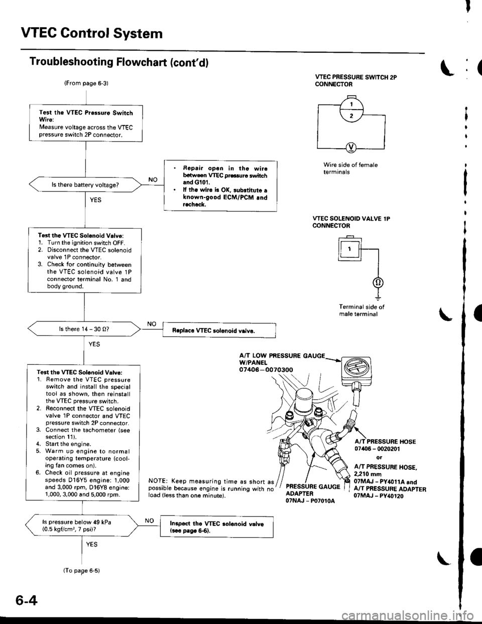
VTEC PRESSURE SwlTCH 2PCONNECTOR
Wire side of female(€rmrnats
VTEC SOLENOID VALVE lPCONNECTOR
I r----'t I
ll ' ff---r'�-'�1
I
I
-L
Terminal side ofmale terminal
A/T LOW PRESSUREw/PAt{EL07406-0070300
NOTE: Keep measuring time as short aspossible because engine is running with noload (less than one minute).
PRESSURE GAUGEADAPTER07NAJ - P07010A
A/T PRESSURE I{OSE07406 - 0020201
ot
A/T PRESSURE HOSE.2,210 mm07MAJ - PY&llA andA/T PRESSURE ADAPTER07MAJ - PY,()120
6-4
(From page 6-3)
(To page 6-5)
Test the VTEC Pr6suro SwitchWiro:Nleasure voltage across the VTECpressure switch 2P connector.
. Rcpai. opon in tho wirebrtw.en VTEC pr6.urc switchand G101.. lf th. wir6 b OK, sub.thuto alnown-good ECM/PCM !ndracheck.
ls there baftery voltage?
Te3t the VTEC Solonoid V.lve:1. Turn the ignition switch OFF.2. Disconnect the VTEC solenoidvalve 1P connector.3. Check for continuity betweenthe VTEC solenoid valve 1Pconnector terminal No. 1 andbody ground.
ls there 14 - 30 0?
Te3t tho WEC Solonoid Vatvo:'1. Remove the VTEC pressureswatch and install the specialtool as shown, then reinstallthe VTEC pressure switch.2. Reconnoct the VTEC solenoidvalve 1P connector and VTECpressure switch 2P connector.3, Connect the tachometer (seesection 11).4. Stan the engine.5, Warm up engine to normaloperating temperature (cool,ing fan comes on).6. Check oil pressure at enginespeeds D16Y5 engine: 1,000and 3.000 rpm, D16Y8 engine:1,000,3,000 and 5,000 rpm.
ls pressure below 49 kPa(0.5 kgflcm,, 7 psi)?In.poct the VTEC aolonoid vllvols.c p.g. &6).
:(
t
I
t
:
t
I
I
Page 118 of 2189

VTEC Rocker Arms
2.
Manual Inspection (D16Y5 engine)
3.
1.
4.
Set the No. 1 piston at TDC.
Remove the cylinder head cover.
NOTE: Refer to page 6-46 when installing the cylin-
der head cover.
Move the intake secondary rocker arm on the No. 'l
cylinder manually.
Check that the intake secondary rocker arm moves
independently of the primary intake rocker arm,
SECoNDARY PtROCKER ARM. Push and pull.
Check the intake secondary
cylinder at TDC.
rocker arm of each
a lf the intake secondary rocker arm does not move,
remove the primary and secondary intake rocker
arms as an assembly and check that the pistons in
the secondary and primary rocker arms move
smoothly.
a lf any rocker arm needs replacing, replace the pri-
mary and secondary rocker arms as an assembly.
PRIMARY ROCKER ARM
4.
Manual Inspection (D16YB engine)
1.Set the No. 1 piston at TDC.
Remove the cylinder head cover.
NOTE: Reter to page 6-46 when installing the cylin-
der head cover.
Push the intake mid rocker arm on the No. 1 cylin-
der manually.
Check that the intake mid rocker arm moves indepen-
dently of the primary and secondary intake rocker
arms.
MID ROCKERARM
Check the intake mid rocker arm of each cylinder at
TDC,
lf the intake mid rocker arm does not move.
remove the mid, primary and secondary intake
rocker arms as an assembly and check that the pis-
tons in the mid and primary rocker arms move
smoothly.
lf any rocker arm needs replacing, replace the
primary, mid, and secondary rocker arms as an
assemory.
5,
6-7
Page 121 of 2189
VTEC Rocker Arms
Inspection Using Special Tools (D16Y8 enginel
CAUTION:
o Before using the Valve Inspection Tool. mak6 surethat the air pressure gauge on the air comprsssor
indicates ovor 400 kPa {4 kgf/cm,, 57 psil.
. Inspect th6 valve clearanco before rockar arm inspec-
tion.
. Cov€r th€ timing belt with a shop towel to protect
the bolt.
. Check tho intake prima.y rockff arm of each cylindel
at TDC.
1.Remove the cylinder head cover.
NOTE: Refer to page 6-46 when installing the cylinder
neao cover,
Plug the relief hole with the specialtool.
OTLAJ - PR3O2OB
I,^ A IAo- tu
3. Remove the sealing bolt from the inspection hole
ancl connect an air pressure regulator with a 0 - 100psi gauge.
l0 x 1.0 mmSEALING EOLT20 N.m (2.0 kgf.m, 14 lbf.ft)
(AIR PRESSUREREGULATOR
{Commerciallyavailable). Pullthe dialandturn to adjust,
Page 123 of 2189

Valve Clearance
Adjustment
NOTE:
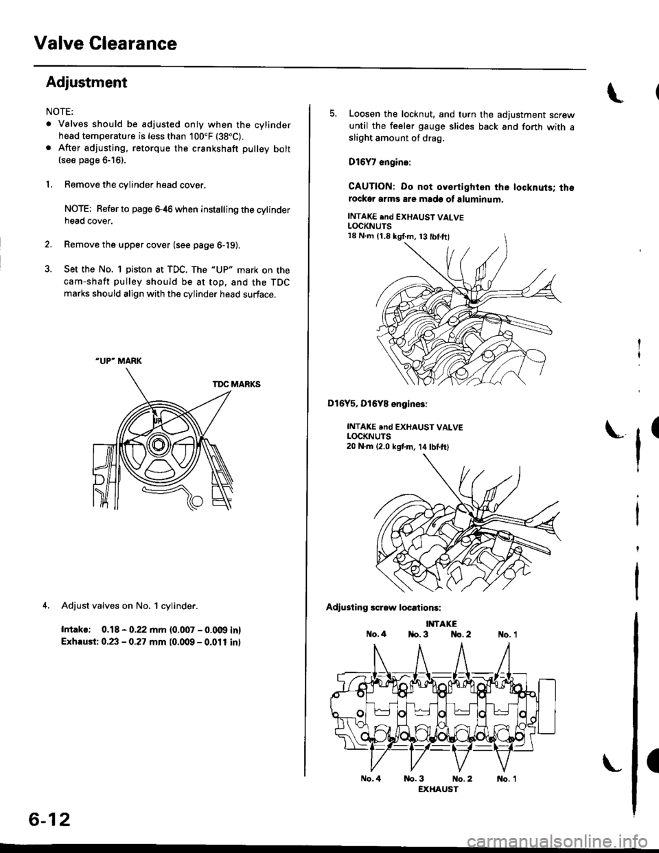
. Valves should be adjusted only when the cylindsrhead temperature is less than 100"F (38"C).
. After adjusting, retorque the crankshaft pulley bolt(see page 6-16).
1, Remove the cylinder head cover.
NOTE; Refer to page e46 when installing the cytinderhead cover.
2. Remove the upper cover (see page 6-19).
3. Set the No. 1 piston at TDC. The "UP" mark on the
cam-shaft pulley should be at top, and the TDC
marks should align with the cylinder head surface.
TDC MARKS
4. Adjust valves on No, 1 cylinder.
Intako: 0.18 - 0.22 mm {0.007 - 0.009 in}
Exhaust: 0.23 - 0.27 mm (0.009 - 0.011 inl
"UP" MARK
6-12
No.4
5. Loosen the locknut, and turn the adjustment screwuntil the feeler gauge slides back and forth with asliOht amount of drag,
D16Y7 engin.:
CAUTION: Do not oyertighlen the locknuts; thorockor arms are made of aluminum.
INTAKE end EXHAUST VALVELOCKNUTS
Dl6Y5, Dl6Y8 engin€3:
INTAKE .nd EXHAUST VALVELOCKNUTS20 N.m 12.0 kstm, 14lbtft)
Adiusting screw locations:
IMTAKEo.4 1{o. 3 No. 2
tr'
(
nb.3 No.2 No. 1EXHAUST
18 N.m (1.8 kgI.m, 13 tbl.ftl