1997 HONDA CIVIC Starting
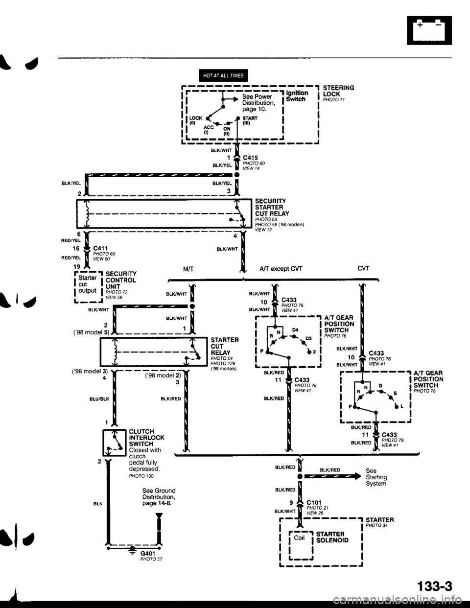
[x] Cancel search: StartingPage 2045 of 2189
\.
!l f-+ iffi,iiilili. lsivvncrr I
ii^ / _;l"d:lt':"i i:ll*cK ( - t*.r.$r Ii!tff^.I^-.-f fl''i" I r
i! ti't|l ! rL---------J-{,5=;==---)"'*TA
"o'uetxret I Pflllodo
l:'iISECURITYSTARTERCUT RELAYPHOTO 53PTOIO 56 ( 98 modsls)vlEW 12
STEERINGLOCK
a
lll except CW
!'G";1cutouiput
SECURIryCONTROLUNIT
vtEw 58
MrrCVT
;BLKTTVHT
('98 model 5)
"a*-", Io
.I A/T GEARI POSTflONa swtTcHPHOfO 78STARTERCUTRELAYfrc433Bt( vHT
10aL|( vHr('98 model 3)4
BLU/BLK
--T6-';'d"r tlf3l
".,u".o I
T
I
cLUrcH llTNTERLoCK I
Slig:i* J,clutchpedalfullyoepresseo.
8LK/FED11t A/T GEARI POSTTTONa swrTcH
I
I
IJ
c433ot-r\
L!
BLKRED
".o"ro! BLvFEo.@
"'o"'r"f,
"'ot
ro'ffzr----,
SeeStartingSystemSe€ G.oundDistribution,page l4$.
BLKAVHTTY
II
L____l+.: G401PHOTO 57
STARTER
r::1 STARIER
I uo'r I soLE orD
tl
;-
".orr.i tr-
- -
to :l cat t
*"1.;
[;z*e'
an
L---J---ALI(RED
",#"It#f;,.+,"
rl r
L--------J
133-3
Page 2049 of 2189
STEEBINGLOCK
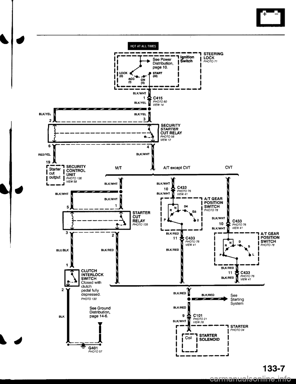
SECURITYSIARTEFCUT RELAYPHO|O 56vtEw 12
MrtA/f sxcept CWcw
BLKAIIIfITIo
"'li'l
t**,"BLK,^,HI ll V/Ew 4 r
c433PHOIO 76
BLKr{VHT't0
BLK/IIT/HT
TXa.ta
t
II
,I
I
I
I
I
I
POSTTtONswrTcH
STARTERcurRELAYPHO|O 135
\*
l:l
I
------;r
I
",-o"ao IT
I
cLUrcH i
$fri*'fl:J Iclutch -
pedalfullyoepresseo.PHO|O 130
c433I
t-
BLK/FED
A/T GEARPOStTtONswtTcH*\"
LL
"."JJ"!F;?',?,-
".o"ro! BLKFEDo@SeeStarting
STARTER
Seo GfoundDistribution,page 14-6.)21I
c101
vtEw 2l2A
il
System
START
r::-1 STAHTER
I uo" lsoLENotD
tl
ii-=1;-i*r*iTfifil I
il.^-.. ./ _ r.n:'o ! r
!!r3"'.rhil.1ilr- i !--ii-;;;I'-----==----
**,^r..! i'i"i'
"-dI
iryissu'Y
\.
L--------J
34
133-7
Page 2054 of 2189
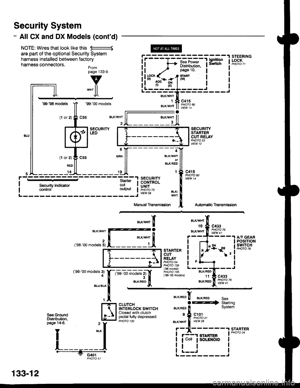
Security System
- All CX and DX Models (cont'd)
NOTE: Wires that look like this S--------S
are part ol the optional Security System
harness installed between lactory
harness connectors.Frompage j33_9.
@
aLI(AVHI
IAIKWHT
STEERINGLOCK
v
""'ll
'99198 models
(l or
1T
Jl.
'99100 models
sEcuRrwLEO
c415
vlEw 14
l-
SECURITYSTARTERCUT RELAYPHO|O 53vtEw 12
BLI(FEO't1
au(/FEo
c433
Aubrnatb Transmission
c4r 5PHOTO N
AU(WHT't0
BLXAVI{TBLKT'!VHT
2('98-'00 mod€ls 5)
('98100 models 3)4
A"IT GEARPOStTTONswtTcH
".**"rI
[ :,iSTARTERCUTRELAYPHO|O 54PHO|O 129( 9€ model)
( 9+ 00 models)
?
I
I
I
I
I
1-sel-oo rnJ"ls z1'[
".*"9tr
c433
CLUTCHINTERLOCK SWITCHClosed with clutchpedaltully depressed.
".o""0! ".o".0 seeaE4 Starting
ar-rvneo ll System
'f, "";%,,BLK TTBT I
vrEw28
r-11------.|STABTER
! r3r smnren I PHoro 34
| 1 coit ; SoLENOID I
i !.__J iL--------J
"===-F=F*F,Ff
Tfo?"
It -,/ Pase 10 l
!ltb3'-fi:-#-1iln i
ll .",;T; "":JI------;;lt
ll *"ll ll ELKBEDII
,JL----- 'dl*------ 'll t{
paso 14€. " y
I
*-l
L_______l.------+;_ -
PHO|OST
133-12
Page 2069 of 2189
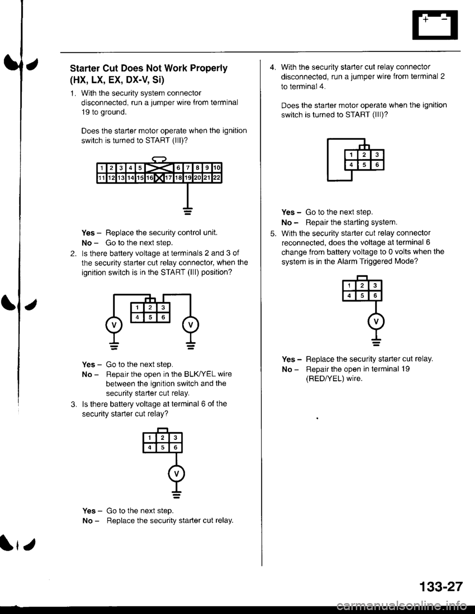
Starter Cut Does Not Work Properly
(HX, LX, EX, DX-V, Si)
1 . With the security system connector
disconnected, run a jumper wire f rom terminal
19 to ground.
Does the starter motor operate when the ignition
switch is turned to START (lll)?
2.
Yes - Replace the security control unit.
No - Go to the next steD.
ls there baltery voltage at terminals 2 and 3 of
the security starter cut relay connector, when the
ignition switch is in the START (lll) position?
Yes - Go to the next step,
No - Reoair the ooen in the BLK/YEL wire
between the ignition switch and the
security starter cut relay.
ls there battery voltage at terminal 6 of the
securitv starter cut relav?
Yes - Go to the next steo.
No - Replace the security starter cut relay.
3.
@
I=
r
133-27
4. With the security starter cut relay connector
disconnected, run a jumper wire from terminal 2
to terminal 4.
Does the slarter motor operate when the ignition
switch is turned to START (lll)?
5.
Yes - Go to the next step,
No - Repair the starting system.
With the security starter cut relay connector
reconnected, does the voltage at terminal 6
change from battery voltage to 0 volts when the
system is in the Alarm Triggered Mode?
Yes - Replace the security starter cut relay.
No - Repair the open in terminal 19
(BED/YEL) wire.
4
I=
Page 2070 of 2189
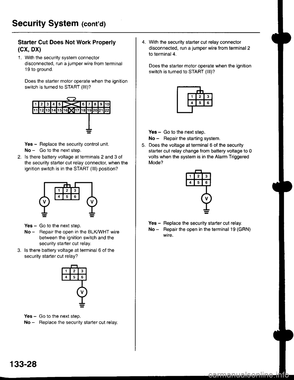
Security System (cont'd)
Starter Cut Does Not Work Properly
(cx, Dx)
1 . With the security system connector
disconnected, run a jumper wire f rom terminal
19 to ground,
Does the starter motor operate when the ignition
switch is turned to START (lll)?
Yes - Replace the security control unit.
No - Go to the next steo.
ls there battery voltage at terminals 2 and 3 of
the security starter cut relay connector, when the
ignition switch is in the START (lll) position?
Yes - Go to the next step.
No - Repair the open in the BLKMHT wire
between the ignition switch and the
security starter cut relay.
ls there battery voltage at terminal 6 of the
securitv starter cut relav?
Yes - Go to the next step.
No - Beplace the security starter cut relay.
4
o
t_=
133-28
4. With the security starter cut relay connector
disconnected, run a jumper wire from terminal 2
to terminal 4.
Does the starter motor operate when the ignition
switch is turned to START (lll)?
Yes - Go to the next steo.
No - Repair lhe starting system.
Does the voltage at terminal 6 of the security
starter cut relay change trom battery voltage to 0
volts when the system is in the Alarm Triggered
Mode?
Yes - Replace the security starter cut relay.
No - Repair the open in the terminal 19 (GRN)
wtre.
q
I=
Page 2118 of 2189
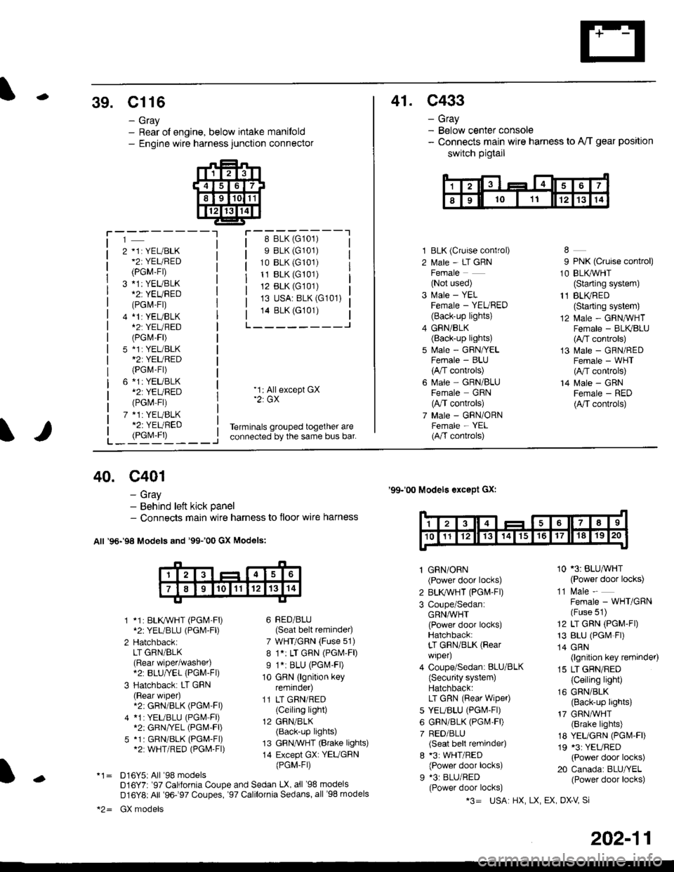
-39. Cl16
- Gray- Rear ol engine, below intake manifold- Engine wire harness junction connector
41. C433
- Gray- Below center console- Connects main wire harness to A'/T gear position
switch pigtail
i-'-j-----lr-:-_-::::^-_---'18 BLK (G101)
s BLK (G101)
10 BLK (G101)
11 BLK (G101)
12 BLK (G101)
13 USA: BLK (G101)
14 BLK (G101)
L___-----J
2 *1: YEL/BLK*2iYEURED
(PGM-Fr)
3 *1: YEUBLK
(PGl\4-Fr)
4 *l:YEUBLK*2T YEURED(PGr\4-F|)
5 *1i YEL/BLK*2: YEURED(PGM-Fr)
6 *1: YEUBLK*2: YEURED(PGM Fr)
7 *1: YEUBLK*2: YEURED
1 BLK (Cruise conlrol)
2 l\,1ale - LT GRNFemale(Not used)
3 Male - YELFemale - YEURED(Back-up lights)
4 GRN/BLK(Back-up lights)
5 f,rale - GRN/YELFemale - BLU(A,/T controls)
6 l\.4ale - GRN/BLUFemale GRN(A,/T controls)
7 Male - GRN/ORNFemale - YEL(A/T conkols)
9 PNK (Cruise control)
1O BLI(WHT(Starting system)
11 BLI(RED(Starting system)
12 Male - GRNIVHTFemale - BLK/BLU(A,/T controls)
13 Male - GRN/REDFemale - WHT(A,/T controls)
14 Male - GRNFemale - RED(A,/T controls)
L_i9yj'L____i
'1: Allexcept GX'2: GX
Terminals grouped together areconnected by the same bus bar.
40. c401
- Gray- Behind left kick panel- Connects main wire harness to floor wire harness
All '96-'98 Models and '99100 GX Models:
1 *1: BLKWHT (PGM-F|)*2:YEL/BLU (PGl\4'Fl)
2 HatchbackiLT GRN/BLK(Rear wiper/washer).2: BLU/YEL {PGM-Fl)
3 Hatchback: LT GRN(Rear wiper).2: GRN/BLK (PGM'Fl)
4 *1:YEUBLU (PGM Fl)*2: GRN/VEL (PGl,I-Fl)
5 *1: GRN/BLK (PGM-FI)*2: WHT/RED (PGl\4-Fl)
*1= D16Y5iAll '98 modelsD16Y7r '97 California Coupe and Sedan LX, all '98 models
D16Y8: All '96-97 Coupes, '97 Calilornia Sedans, all '98 models
*2= GX models
'99-'00 Models except Gx:
6 BED/BLU(Seat belt reminder)
7 WHT/GRN (Fuse 51)
8 1.: LT GRN (PGM'F|)
I 1.i BLU (PGl\.4-Fl)
10 GRN (lgnition keyremrnoer)
11 LT GRN/RED(Ceiling light)
12 GRN/BLK(Back-up lights)
13 GFN,TVHT (Brake lights)
14 Except GX: YEUGBN
{PGM-Fr)
1 GRN/ORN(Power door locks)
2 BLK,ryVHT (PGM-Fl)
3 Coupe/SedaniGRNA/VHT(Power door locks)Hatchback:LT GRN/BLK (Rear
wiper)
4 Coupe/Sedan: BLU/BLK(Security system)Hatchback:LT GRN (Rear wipeo
5 YEUBLU (PGl\4-Fl)
6 GRN/BLK (PGM,FD
7 RED/BLU(Seat belt reminder)
8 *3: WHT/RED(Power door locks)
9 *3: BLU/RED(Power door locks)
10 '3: BLU^VHT(Power door locks)
11 l\.4ale -
Female - WHT/GRN(Fuse 51)
12 LT GRN (PGM-FD
13 BLU (PGr\4 Fr)
14 GRN(lgnition key reminder)
15 LT GRN/RED(Ceiling light)
16 GRN/BLK(Back-up lights)
17 GRN,ryVHT(Brake lights)
18 YEUGRN (PGI\4.FD
19 *3: YEURED(Power door locks)
20 Canada: BLU/YEL(Power door locks)-
*3= USA HX, LX, EX OX-V Si
202-11
Page 2121 of 2189
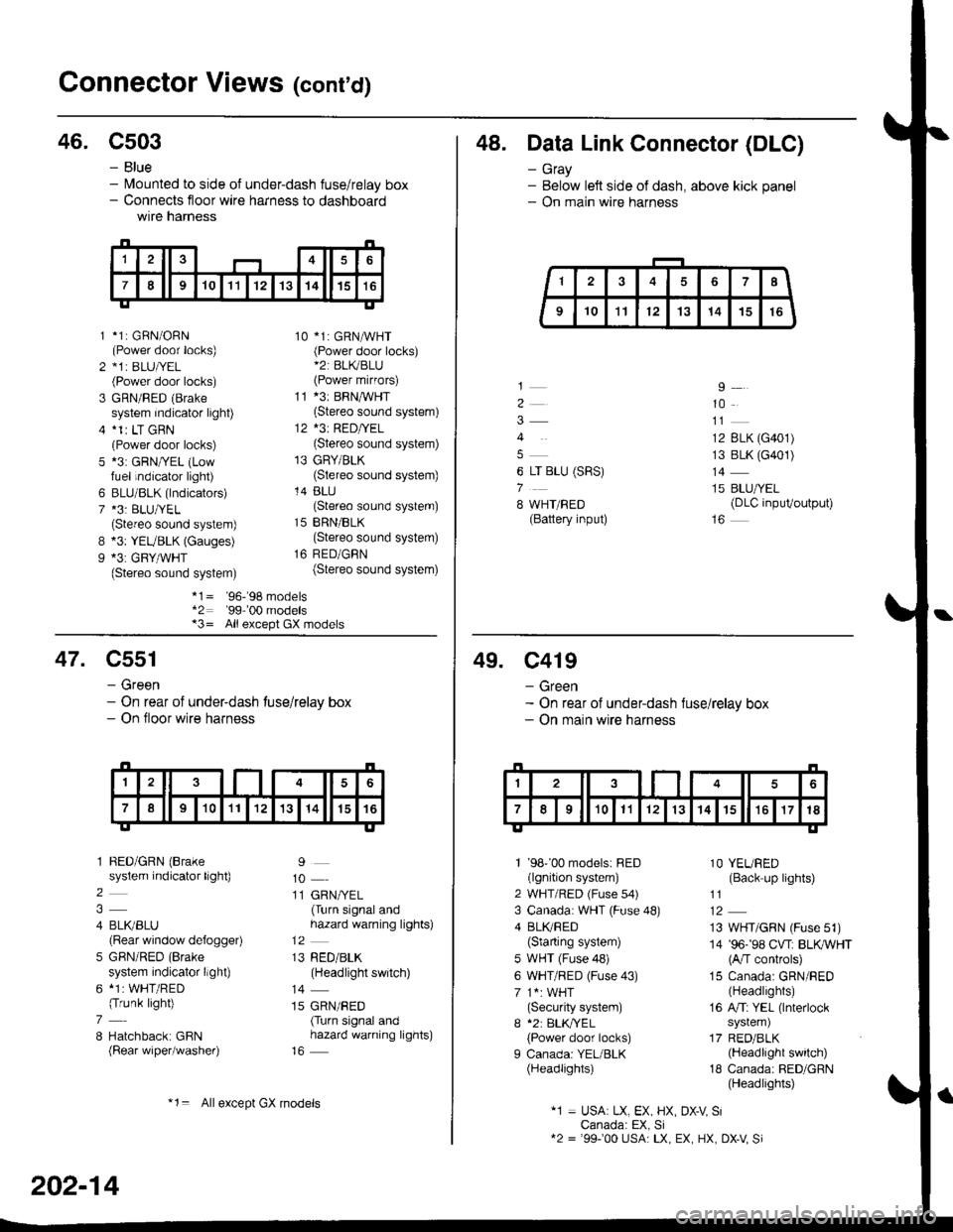
Gonnector Views (conrd)
46. C503
B
9
*1: GBN/ORN(Power door locks)*1r BLU|/EL(Power door locks)
GRN/RED (Brake
system indicator light)*1r LT GRN(Power door locks)*3: GRN/YEL (Lowfuel indicator light)
BLU/BLK (lndicators)*3: BLU/YEL(Stereo sound system)*3: YEUBLK (Gauges)*3: GRY/WHT(Stereo sound system)
10 *1: GRNAVHT(Power door locks)*2: BL(BLU(Power mirfors)
11 *3: BRNMHT(Stereo sound system)
12 *3: RED/YEL(Stereo sound system)
13 GRY/BLK(Stereo sound system)
14 BLU(Stereo sound system)
15 BRN/BLK(Stereo sound system)
16 RED/GBN(Stereo sound system)
- Blue- lvlounted to side of under-dash fuse/relay box- Connects floor wire harness to dashboardwtre narness
1
2
3
5
6
7
*1= '96-'98 models*2: '99-'00 models*3= All except GX models
48. Data Link Connector (DLC)
- Gray- Below left side of dash, above kick panel- On main wire harness
4
6 LT BLU (SRS)
7
8 WHT/BED(Battery input)
9
10
12 BLK (G401)
13 BLK (G401)
14
15 BLU/YEL(DLC inpuVoutput)
47. C551
- Green- On rear of under-dash tuse/relay box- On floor wire harness
1 BED/GRN (Brake
system indicator light)
2
4 BLI(BLU(Rear window defogger)
5 GBN/RED (Brake
system indicator llght)
6 *1: WHT/RED(Trunk light)
7
8 Hatchback: GBN(Rear wiper/washer)
9
10
11 GRN/YEL(Turn signal andhazard warning lights)
13 RED/BLK(Headlight switch)
14
15 GRN/RED(Turn signal andhazard warning lights)
202-14
*1= Allexcept GX models
49. C419
- Green- On rear of under-dash fuse/relay box- On main wire harness
1 '98''00 models: RED(lgnition system)
2 WHT/RED (Fuse s4)
3 Canada: WHT (Fuse 48)
4 BLI(RED(Starting system)
5 WHT (Fuse 48)
6 WHT/RED (Fuse 43)
7 1*: WHT(Security system)
I *2: BLK,TYEL
{Power door locks)
I Canada: YEL/BLK(Headlights)
1O YEURED(Back up lights)
11
13 WHT/GRN (Fuse 51)
14 '96-'98 CVT: BLKWHT(A/T controls)
15 Canada: GRN/RED(Headlights)
16 A/Ti YEL (lnterlock
system)
17 RED/BLK(Headlight switch)
18 Canada: RED/GRN(Headlights)
"1 = USA: LX, EX, HX, DX-V SiCanada: EX, Si12 = '99100 USA: LX, EX, HX, DX-V Si
Page 2126 of 2189
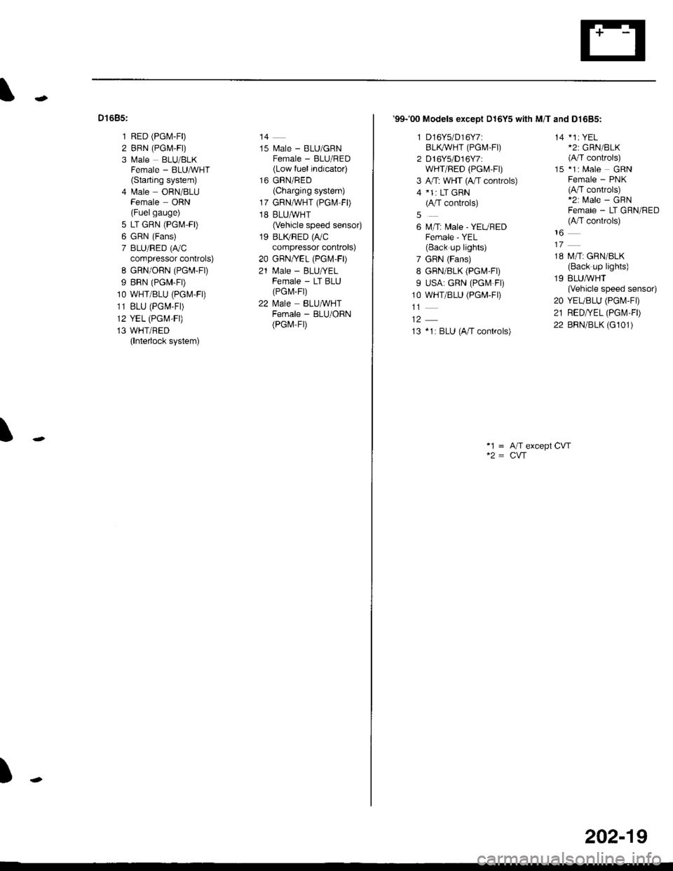
Dt685:
1 RED (PG[,1-F0
2 BRN (PGM,F|)
3 Male BLU/BLKFemale - BLUMHT(Starting system)
4 lrale ORN/8LUFemale ORN(Fuelgauge)
5 LT GRN (PGM-FD
6 GRN (Fans)
7 BLU/RED (r,/C
compressor controls)
8 GRN/ORN (PGM-Fr)
9 BRN (PGM-FD
1O WHT/BLU (PGM.FO
11 BLU (PGM-F|)
12 YEL (PGM-FI)
13 WHT/BED(lnterlock system)
14
15 l\.4ale - BLU/GRNFemale - BLU/RED(Low fuel indicator)
16 GRN/RED(Charging system)
17 GRNA/VHT (PGl\.4 FD
18 BLUAVHT(Vehicle speed sensor)
19 BLTVRED (r,/C
compressor controls)
20 GBN/YEL (PGr\.4-FD
21 N4ale - BLU/YELFemale - LT BLU(PG r\,,r- Fr)
22 l\4ale BLU&VHTFemale - BLU/ORN(PGr,4-Fr)
\
)
'99-'00 Models exceot D16Y5 with M/T and D1685:
1 D16Y5/D16Y7:BLI(WHT (PGM.FI)
2 D16Ys/D16Y7:wHr/RED (PGt\4-Ft)
3 A,rT: WHT (4,/T controls)
4 *1: LT GRN(A/T controls)
6 M/T: Male - YEUREDFemale - YEL(Back up lights)
7 GRN (Fans)
8 GRN/8LK (PG[,4-Fr)
9 USA: GRN (PGf.4 Fl)
1O WHT/BLU (PGM-FD
13 *1: BLU (A/T conkols)
14 *1: YEL*2: GRN/BLK(A/T controls)
15 *1: Male GRNFemale - PNK(A/T controls)*2: Male - GRNFemale - LT GRN/RED(A,fT conkols)
18 M/T: GRN/BLK(Back up lights)
19 BLUMHT(Vehicle speed sensor)
20 YEUBLU (PGI\4-FD
21 RED/YEL (PGt\,'l,FD
22 BRN/BLK (G101)
*1 = A/T except CVT
202-19