Page 829 of 2189
Countershaft
Disassembly/lnspection/Reassembly
NOTE:
. Lubricate all parts with ATF before reassembly'
. tnrp"",,n",t -"t needle bearings and the needle bearings for galling and rough movement'
. Before installing the O-rings. wrap the shaft splines with tape to prevent damaging the O-rings
. Locknut has left-hand threads
LOCKNUT (FLANGE NUT}
23 x 1.25 mm103 N.m
{10.5 kgf'm, 75.9 lbf'tt)
Replace.Left'handlhreads
CONTCAL SPRING
WASHERReplace.
GEAR
CLUTCH
1ST GEAR
BEARING
lST GEAR COLLAR
TRANSMISSIONHOUSING BEARING
REVERSE GEAR
NEEDLEBEARING
SELECTOR
SELECTOR
4TH GEAR
NEEDLE BEARING
DISTANCE COLLAS,
28 mmSelective pa .
COUNYERSHAFTCheck splines lor excesslve
wear and damage
2'{D GEAR
THRUST NEEDLEBEARING
3RD GEAB
NEEDLE BEARING
3RD GEAR COLLAR
THRUST NEEDLE EEARING
SPLINEO WASHER
3RD CLUTCH ASSEMBLY
Check bearing surface for scoring'
scratches and excessive wear'
Replace.
1+151
Page 830 of 2189
Countershaft
Disassembly/Reassembly
1. Using a hydraulic press, press out the countershaftwhile supporting 4th gear.
NOTE: Place an attachment between the press andthe countershaft to prevent damage to the shaft.
CAUTION: Do not allow the countershaft to fall andhit the g.ound when pressed clear.
14-152
2. Assemble the parts on the countershaft as shownoetow.
NOTE;
. Lubricate all parts with ATF during assembly.. Before installing the O-rings, wrap the shaft splineswith tape to prevent damaging the O_rings.
4TH GEAR
NEEDLE EEARING
DISTANCE COLLAR, 28 mmSelective part.
2ND GEAR
THRUST NEEOLE BEARING
3RD GEAR
NEEDI.E EEARING
3RO GEAR COLLAR
THRUST NE€OLE BEARING
SPLINED WASHER
3RD CLUTCH ASSEMBLY
O.RINGSReplace.
COUNTERSHAFT
Page 833 of 2189
One-way Clutch
Disassembly/lnspection/Reassembly
1. Separate countershaft 1st gear from the park gear
by turning the park gear in the direction shown
2. Remove the one-way clutch by prying it up with the
end of a screwdriver.
COUNTERSHAFT 1ST GEARONE-WAY CLUTCHNOTE: lnstall in this direction.
ONE'WAY CLUTCH
COUNTERSHAFT lST GEAR
COUNTERSHAFT lST GEAR
SCREWORIVER
14-155
3. Inspect the parts as followsl
PARK GEARInspecl the park gear
for wear and scorrng.
ONE-WAY CLUTCHInspect the one-way
clutch for damage and
laulty movement.
lST GEABInspect countershalt lst gear
for wear ancl scorlng.
After the parts are assembled, hold countershaft 1st
gear and turn the park gear in the direction shown
to be sure it turns freely. Also make sure the park
gear does not turn in the opposite direction.
Page 840 of 2189
Clutch
Reassembly
NOTE:
. Clean all parts thoroughly in solvent or carburetor
a
cleaner, and dry them with compressed air.
Blow out all passages.
Lubricate all parts with ATF before reassembly.
Inspect the check valve; if it's loose, replace the pis-
to n.
1.
CHECK VALVE
2. Install new O-rings on the clutch piston.
O RINGS
PISTON
-
14-162
3. Install the piston in the clutch drum, Apply pressure
and rotate to ensure proper seating,
NOTE: Lubricate the piston O-ring with ATF beforeinstalling.
CAUTION: Do not pinch the O-ring by insta ing thepiston with too much force.
CLUTCII DRUM
Install the return spring and spring retainer, andposition the snap ring on the retainer.
CLUTCI{ DRUM
Page 842 of 2189
Glutch
Reassembly (cont'd)
7. Installthe snap ring.
Removs the special tools.
Install the disc spring.
NOTE: Install the disc spring in the direction
shown, except 2nd clutch.
SNAP RING
8.
o
14-164
h
10.
ll.
Soak the clutch discs thoroughly in ATF for a mini-
mum of 30 minutes.
Starting with a clutch plate, alternately install the
clutch plates and discs. Install the clutch end plate
with flat side toward the disc.
NOTE: Before installing the plates and discs, make
sure the inside of the clutch drum is free of din orother foreign mafter.
CLUTCH END PLATEInstall in this direcrion.
12. Installthe snap ring.
SCREWDRIVER
SNAP RING
Page 844 of 2189
Differential
lllustrated lndex
BOLT10 r 1.0 mm'10'l N'm (10.3 k91.m,74.5 lbf.ftlLeft-hand threads
SET RING, 80 mrrt
FINAL DRIVEN GEARInspect tor excessive wear.Install in this direction.
efef
BALL BEARINGInspect for faulty movement.
DIFFERENTIAL CARRIERInsoect for cracks,
ROLLER,5x10mmSPEEDOMETER ORIVE
GEARlnstall in this direction.
SNAP RINGInstall in this direction.
EALL BEARINGInspect for faulty movement-
-
14-166
Page 845 of 2189
Backlash lnspection
1. Place differential assembly on V-blocks and install
both axles.
Check backlash of both pinion gears
Standard {Now): 0.05 - 0.15 mm {0.002 - 0.006 in)
lf backlash is out of tolerance, replace the differen-
tial carrier.
Bearing Replacement
NOTE: Check bearings for wear and rough rotation. lf
bearings are OK, removal is not necessary.
1, Remove bearings using a bearing puller.
BEARING PULLER(Commerci6lly available)
2. Install new bearings using the specialtool as shown.
14-167
Page 848 of 2189

Differential
Oil Seal Installation/Side Clearance (cont'd)
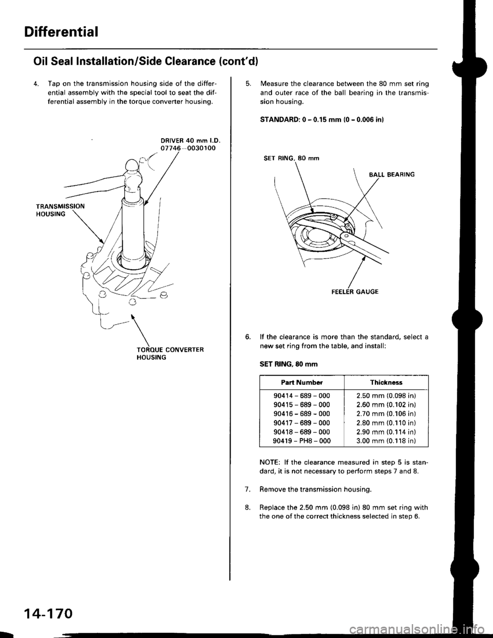
4. Tap on the transmission housing side of the differ-
ential assembly with the special tool to seat the dif-
ferential assembly in the torque converter housing.
DRIVER 40 mm l.D.
L
14-170
5. N4easure the clearance between the 80 mm set ring
and outer race of the ball bearino in the transmis-
sion housing.
STANDARD: 0 - 0.15 mm (0 - 0.006 inl
SET RING, 80 mm
BALL BEARING
lf the clearance is more than the standard, select a
new set ring from the table, and install:
SET RING, 80 mm
NOTE: lf the clearance measured in step 5 is stan-
dard, it is not necessary to perform steps 7 and 8.
Remove the transmission housing.
Replace the 2.50 mm (0.098 in) 80 mm set ring with
the one of the correct thickness selected in step 6.
7.
Part NumberThickness
90414-689-000
904r5-689-000
90416-689-000
90417-689-000
90418-689-000
904r9-PH8-000
2.50 mm (0.098 in)
2.60 mm {0.102 in)
2.70 mm {0.106 in)
2.80 mm (0.110 in)
2.90 mm (0.114 in)
3.00 mm (0.118 in)