Page 1943 of 2189
UNDER-HOODABS FUSE/RELAY BOX
r------1
c356
FUSE 63MTNCHECK7.54
c357 2
FUSE 61PUIiPolon
c356
ABSPUMPMOTOR
i-.t_____l
*fitr
3
YEURED
A19
(PMR) (MCK) IPump Motor Icomm6n motdr check IRight rear ABS LeftftontABS ;i; !
solenoid control solenoid controt loni of !
\^li Service.check DLC I
/ connector input inpuvoltput i&------ ---_____J
11.I A14 r aBs coNrRor_lrNrBRN I rr eru I LT BLU vttt 63trrt sRS. ATcontrols t-! vccvnv 1"Tl 'Tl ':c360
SERVICE DATA LINKCHECK CONNECTORCONNECTOR (DLC)PHoIo 83 See GrOUnd pHOrO so
Pll'lo.,jpn. p y:l:!:1
*L_T'=Llj:t
See Ground
'--=-Ea; *---==4oi
RightRearABSSolenold(Out)
nightReerABSSoloroid(ln)
LettFrontABSSolenoid(od)
PHA|A 125 PHOfO,/
44-1
Page 1945 of 2189

- How the Circuit Works
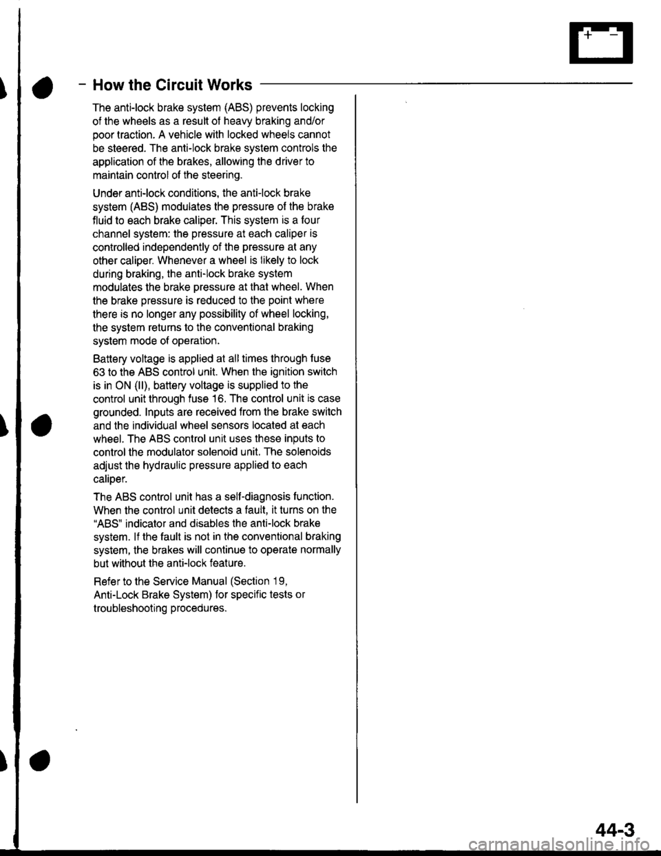
The anti-lock brake system (ABS) prevents locking
of the wheels as a result of heavy braking and/or
poor lraction. A vehicle with locked wheels cannot
be steered. The anti-lock brake system controls the
application of the brakes, allowing the driver to
maintain control of the steering.
Under anti-lock conditions, the antilock brake
system (ABS) modulates the pressure of the brake
tluid to each brake caliper. This system is a four
channel system: the pressure at each caliper is
controlled independently of the pressure al any
other caliper. Whenever a wheel is likely to lock
dunng braking, the anti-lock brake system
modulates the brake oressure at that wheel. When
the brake pressure is reduced to the point where
there is no longer any possibility of wheel locking,
the system returns to the conventional braking
system mode of operation.
Battery voltage is applied at all times through fuse
63 to the ABS control unit. When the ignition switch
is in ON (ll), battery voltage is supplied to the
control unit through fuse 16. The control unit is case
grounded. Inputs are received from the brake switch
and the individual wheel sensors located at each
wheel. The ABS control unit uses these inputs to
control the modulator solenoid unit. The solenoids
adjust the hydraulic pressure applied to each
calioer.
The ABS control unit has a self-diagnosis function.
When the control unit detects a fault, it turns on the"ABS" indicator and disables the anti-lock brake
system. lf the fault is not in the conventional braking
system, the brakes will continue to operate normally
but without the anti-lock feature.
Refer to the Service Manual (Section '19,
Anti-Lock Brake System) for specific tests or
troubleshooting procedures.
44-3
Page 1946 of 2189

Supplemental Restraint System (SRS)
(
FUSE 13FUELPUUPFBA UMT)15A
See PowerDistibution,page 10-2.
FUSE 23(sRs)
c801PHOTO 58
SRS MEMORY ERASESTGNAL (MES) CONNECTORPHO|O 111
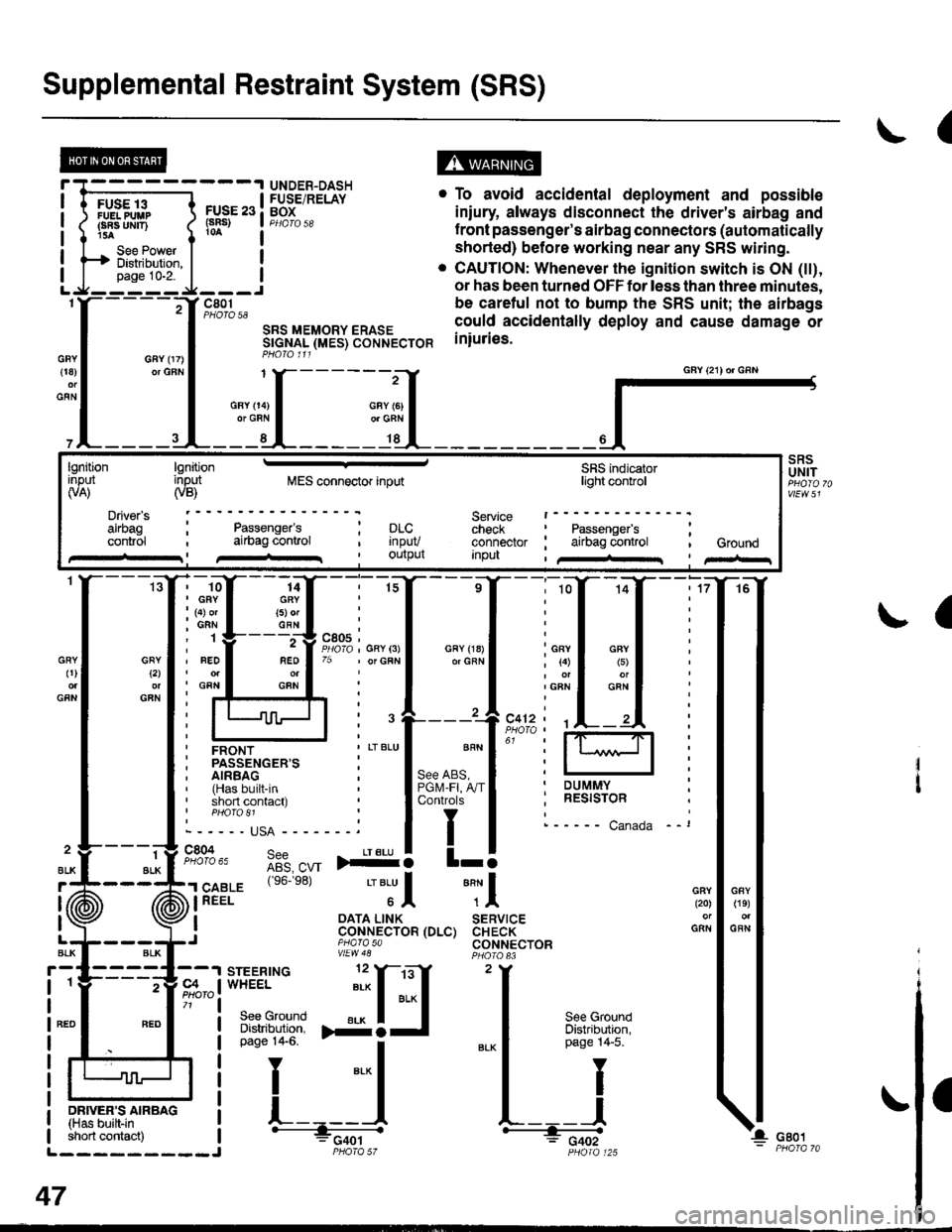
. To avoid accidental deployment and possible
iniury always disconnect the driver's airbag and
f ront passenger's airbag connectors (automatically
shorted) before working near any SRS wiring.
. CAUTION: Whenever the ignition switch is ON (tt),
or has been turned OFF for less than three minutes,
be caretul not to bump the SRS unit; the airbags
could accidentally deploy and cause damage or
iniuries.
UNDER-DASHFUSE/RELAYBOX
GFY 07)or GFN{18)
GFN
GFYt2l
GFN
GRY0)
GFN
2
ALK
J (ii
t\
GFY O4)or GRN
SRSUNIT
a
-ffiffi,*l-{
H!=";=_J
iffii'r:fi:*" i tH-
PHOIO 125short contact) | - FCqOtL_________J PHO|A 57
47
GAY (21) or GRN
lgnitionInput(VA)
Driver's
cont.ol
lgnitioninput(VB)MES connector inputSRS indicatorlighl control
Service t------check : Passengefs ;connector ; airbag control , GroundInpu , /+rr I pir-r
Passenger'sai|bag conlrol; prc..t rnpuv, Ourpul
14GRY(5) orGFN
rffi{{_ilil
i ffi i""'"1*"o,"'.1'' i lffil
ffirtu!-T:l
ir:r*::"."
ilstEl'{s6.e8'�
'"'Jl "Tl
, I oATA L|NK SERVTCE: CoNNECTOR (DLC) CHECK,J piarasa CONNECTORvtEw48
Page 1948 of 2189
Blower Controls
'96-'98 Models
@
UNDER.HOODFUSE/RELAYBOX
UNDER.DASHFUSE/RELAYBOXPHOTO 5A
BLOWEFnoToRBELAYPEOfO I
HEATER FANSWITCH
6 calrSeeL/cCompressorControls
(
See GroundDbtribution,oaqg 14-5.
See GrorDbtributipage 14.
I
I
_l
ar<
L
- c402
BLU/YEL1l
BLU/
1BLK
BLK
BLK
60
Page 1949 of 2189
- '99-'00 Models
i-F;;t
L-t'::-i
"d[ft?"l'
UNDER.HOODFUSE/RELAYBOX
UNDER-DASHFUSE/RELAYBOXPHOTO 58
iGi'i'-----'lBEATEA,'/C RE|AY7.5A
".*1.[F*ft"
See PowerDist.ibution,
FUSE 55HEAIERt/toToR
page 10"9.L-*----::--J
BLU
n
$
Se€ PowsrDl8tdbution,pago 1O11.
g€e PowsrDlslribution,pag€ lGg,
ALOWEFmoToRREIAYPHOTO Il1
BIUBLIVYEI
813
OFN/WHT
BLK
2BIK
G402G402
"lSi:lf:::' >-1
-".. i c.u, I--';-lP;!o;i: I---------J
l ,f 3ffJ?il3'o'"o'o*'on
L __ f_---_-_ :::::: - --- r-- -- J
-f-***;
;Iru
I 'rr l-'n BLowER---:-----.l I A lm-o-roC'------------a---E eaoz - I( M rlProraE3PHoro 12s I Y I=----GG-a -
vtEvl 57c440
Se€ Ground
".","i-l'
Ea
JI
6BLOWERMOTORTIIGHRELAYPHO|O 83
UNDER.HOOOFUSE/RELAYBOX
t
!.-
1 HEATER I"-'FI POWERt Battory lgnition Blower I CONTROL I | | rAlHStStOni (brckup) input molor i pAHel I I I pHoro 13e
I ,,o*", _ ffJtt' t PHoro tr7 | tt I
i motor Power ' 'Jback I wr'vzo
I ;_ |! high relay transislor
Ls::s1gl-tt:---J lJ J I
A6
alK
See GroundOistribution,page '14-5.
za
60-1
Page 1951 of 2189
I
MODECONTROLMOTOR
;T
___"rt
1[
___l:il
,rlK
YEUBEO
_:o_
YEUBED
8t
HEATERCONTROLPANEL
I
I
I
t
\.l
t
lleatSwltch
c723
138
it
VenlSwltch
\
I
I
I
I
c723
S9e GroundDistribution,page 14-5.h
-_l
G402
:",;[----
1
61-1
Page 1952 of 2189
![HONDA CIVIC 1997 6.G Workshop Manual Air Delivery
- 99-00 Models
a
r--T----.I UNDER-HOOD UNDEB-DASH
| ,ry:i.l? IFUSE/RELAY I t::u:E^tt l:usE/RELAyi
- -{-;;; -
I PJ,.,8.J390 i
-
T;; ;
- - - - -
I H$3,,8
i 1;:t"* ];FPJ", i i m. HONDA CIVIC 1997 6.G Workshop Manual Air Delivery
- 99-00 Models
a
r--T----.I UNDER-HOOD UNDEB-DASH
| ,ry:i.l? IFUSE/RELAY I t::u:E^tt l:usE/RELAyi
- -{-;;; -
I PJ,.,8.J390 i
-
T;; ;
- - - - -
I H$3,,8
i 1;:t"* ];FPJ", i i m.](/manual-img/13/6068/w960_6068-1951.png)
Air Delivery
- '99-'00 Models
a
r--T----.I UNDER-HOOD UNDEB-DASH
| ,ry:i.l? IFUSE/RELAY I t::u:E^tt l:usE/RELAyi
- -{-;;; -
I PJ,'.',8.J390 i
-
T;; ;
- - - - -
I H$3,',8
i 1;:t"* ];FPJ", i i m'.u" se€power i "t8L,,
i t i a l'"0 r3l",lli"i:" aL--{..-----J L-J..----5::---:-J
"",":"rfi?ll, '[r;T:1"
-",*"1-J
*-*..l
,n", ".u I lt I
lr !I See Power I See Power Distnbution.I Distribution, U page 1o-9.
,, L::':l------- *Y=l
"*o "."",,t
[
*,:.'.Y%
Irel-
lt
:'l-4riffi
MODECONTROLMOTOR
;L:L{;I{,tt't{ {f
SensorGround grgund
venl
Air mix5Y poientia,reTgrano9 rnrrul
gIouno
RecircSwilcfi switchcommon mput
Recirc S$,itchtED LEDcontrol common
RECIRCULATIONCONTROLMOTORPHOTO 139
CONTROLPANEL
vtEw 76
So€ Roar II Windolv :
a
Htr Ttr =tr ;l *tr :tr *,tr THtr Ttr =tr ;l *tr :tr *tr Ttr
'il
Ti
Battery lgnition Mod€ Mode Mode L4ode Mode l od€(back up) input detrost h€av heat heav vent motorR€circulato Fresh
IJ
Delogger
L------- ---J
HEATERPUSHswtTcHEs
delrost
Air Airmix mixcool hot;;-; J'J - - - J-JL i- 5:- - -
SLK
812
AFN
13
BFN
See GroundDistribution,page 14-5.
c4 t, cl
WHT I ONN
ft++il
c723
F ash/RoclreSwftch
Reclrc.oat LEo
IY
tt
L__l--tGo3,
See RearWindowOetogger
AIR MIXTURECONTROLMOTOR
(
c9 Y cl1
61-2
Page 1953 of 2189

- How the Circuit Works
'96198 Models
The air delivery system directs the flow of air used
by the heater and air conditioner systems.
Mode Selection
Mode selection is controlled by the mode switches
in the heater control panel and the mode control
motor. When you select a specific mode, voltage is
applied through the dimming circuit to the LED,
which comes on, indicating the mode selected.
Ground is orovided to the mode control motor
though that mode switch. The motor then runs until
the air control door reaches the proper position.
Fresh/Recirculation 56lection
When you press the fresh or recirculation button, a
ground signal is sent from the heater control panel
to the recirculation control motor. The motor then
runs until the recirculation door reaches the proper
position. Battery voltage is also applied through the
dimming circuit to the corresponding LED, and the
LED comes on.
Refer to the Service Manual (Section 21, Heater) for
specitic tests or troubleshooting proc€dures.
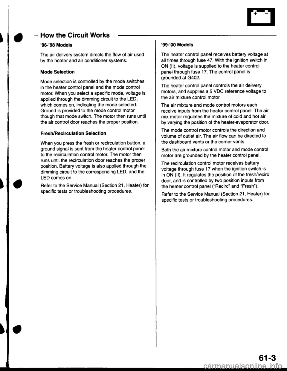
'99J00 Models
The heater control panel receives battery voltage at
all times through fuse 47. With the ignition switch in
ON (ll), voltage is supplied to the heater control
panel through fuse 17. The control panel is
grounded at G402.
The heater control panel controls the air delivery
motors, and supplies a 5 VDC reterence voltage to
the air mixture control motor.
The air mixture and mode control motors each
receive inputs trom the heater control panel. The air
mix motor regulates the mixture of cold and hot air
by varying the position of the heater-evaporator doot
The mode control motor controls the direction and
volume of outlet air. The air flow can be directed to
the dashboard vents or the corner vents.
Both the air mixture control molor and mode control
motor are grounded by the h€aler control panel.
The recirculation control motor receives battery
voltage through fuso 17 when the ignition swilch is
in ON (ll). lt regulates the position of the fresh/recirc
door, and is controlled by two position inputs from
the heater control panel ("Recirc" and "Fresh").
Refer to the Service Manual (Section 21, Heater) tor
specific tests or troubleshooting procedures.
61-3