Page 1304 of 2189
Front Seat
Removal
CAUTION: When prying with a flat-tip screwdriver, wrapit with protective tape lo prevent damage.
NOTE: Take care not to scratch the seat covers and body.
1. Remove the seat track end cover, then remove thebolts.
SEAT TRACKCOVER
FRONT SEAT
)
SEAT TRACKEND COVER
BOLT8 x'1.25 mft22 N..n 12.2 kgl.m,16 rbf.ft)
8 x 1.25 mm22 N.rn 12,2 kgl.m,16 tbtft)
20-74
2. Lift the driver's front seat, then disconnect the seatbelt switch connector.
SEAT BELTswtTcHCONNECTOR
4.
Remove the headrest.
Carefully remove the front seat through the dooropening.
Installation is the reverse ol the removal procedure.
NOTE: Make sure the connector is connected prop-
erry.
5.
Page 1306 of 2189
Front Seat
Replacement (cont'd)
Passenger's (with reclino cablel:
NOTE; Refer to page 20-77 for the recline cable location.
HEADREST
PIVOTWASHER
LOWERCAP
PIVOT NUT8 x 1.25 mm22 N.m 12,2 kgl.m,tbt.ftt
SEAT CUSHION
CENTER COVER
10 x 1,25 mm47 N.m (4.8 kgf.m,
10 x 1.25 mm47 N.m {4.8 kgf.m,3s tbt.ft)
INNER SEATTRACK
35 tbf.ftl
RECLINE ADJUSTEB
RECLINECOVER
i LowER CAP
bRECLINECABLE
x 1.25 mm47 N'm (4.7 kgf.m,35 tbtftl
SEAT
8 x 1.25 mm20 N.m {2.0 kgf.m,14 rbf.ft)
ruf, To connect, twist 180'.
lnstallation is the reverse of the removal procedure.
NOTE:
. Make sure the bushing and pivot washer are
installed properly.
. To prevent wrinkles when installing the seat-back
cover, make sure the material is stretched evenly
over the pad.
. Adjust the recline cable.
. G.ease the sliding ponion.
SEAT-BACK
20-76
Page 1307 of 2189
Harness Wiring and Recline
Cable Locations
NOTE: When installing the seat cushion, make sure the
seat belt switch harness, connector and recline cable are
fastened correctly on the seat cushion frame'
Driver's:>: Clip locations
Passenger's (with lecline cablel:
TRACK
Seat Cover RePlacement
CAUTION: Put on gloves to protest yout hands'
NOTE: Take care not to tear the seams or damage the
seat covers.
Seat-back cover removal:
1. Release the hook, and fold back the seat-back cover'
Release all inside springs, then fold back the seat-
back cover.
Remove the headrest.
Remove the headrest guide, then remove the seat-
back cover.
lnst;llation is the reverse of the removal procedure'
NOTE: To prevent wrinkles when installing a seat-
back cover, make sure the material is stretched evenly
over the pad before securing the inside springs and
hook.
3.
(cont'd)
20-77
HEADREST
Page 1367 of 2189
Seats
Front Seat Disassembly and Reassembly
CAUTION: When prying with a flat-tip screwdriver, wrap it with protective tape to prevent damage.
NOTE: SEAT-BACK. Take care not to scratch the seat covers and body.. Remove the front seat through the door openlng.
Driver's:
SEAT CUSHION
HEADREST
PIVOT NUTI x 1.25 mm22 N.m 12.2 kgf,m,16 tbf.ft)
CENTER COVER
8 x 1.25 mm
LOWER CAP
RECLINE ADJUSTER
WASHER
20 N.m 12.0 kgf.m,lil lbtftl
WASHERS
EUSHING
10 x 1.25 mm47 N.m (4.8 kgf.m,3s rbl.ft)
INNER SEATTRACKRECLINECOVER
WASHER
8 x 1.25 mm20 N.m (2.0 kg,f.m,14 tbf.fit
LOWER CAPI
8 x 1.25 mm20 N.m {2.0 kgI.rn,l4 tbf.ft)
i\",-,"
20-13A
HEIGHT HANDLE
Page 1560 of 2189

lgnition Switch
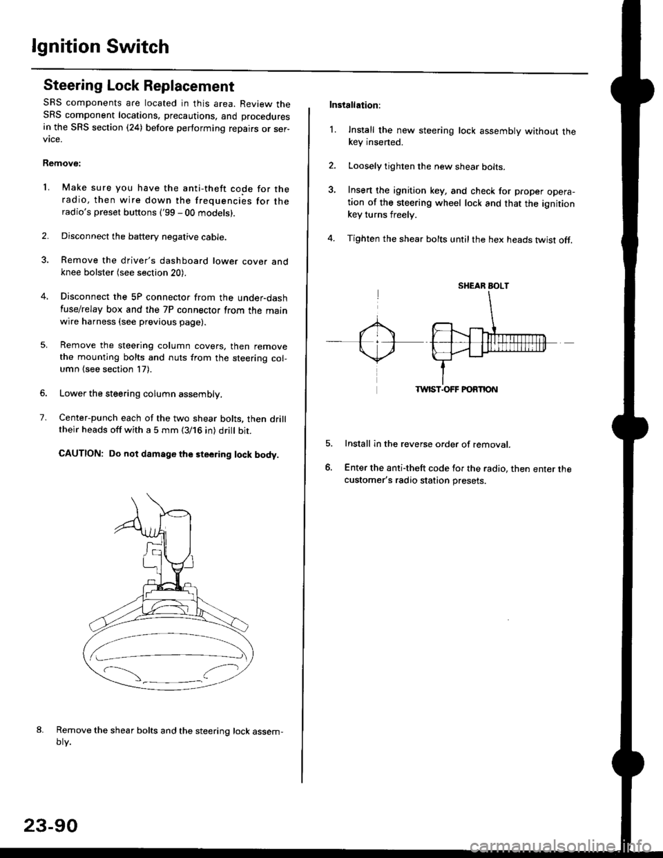
Steering Lock Replacement
SRS components are located in this area. Review theSRS component locations. precautions, and procedures
in the SRS section (24) before performing repairs or ser-vtce.
Remove:
LMake sure you have the anti-theft code for theradio, then wire down the frequencies for theradio's preset buttons ('99 - 00 models).
Disconnect the battery negative cable.
Remove the driver's dashboard lower cover andknee bolster (see section 20).
Disconnect the 5P connector from the under-dash
fuse/relay box and the 7P connector from the mainwire harness (see previous page).
Remove the steering column covers, then removethe mounting bolts and nuts from the steering col-umn (see section l7).
Lower the steering column assembly,
Center-punch each of the two shear bolts, then drilltheir heads off with a 5 mm (3/16 in) dritt bit.
CAUTION: Do not damago the steering lock body.
Remove the shear bolts and the steering lock assem,oty.
2.
1.
23-90
Installation:
l. Install the new steering lock assembly without thekey insened.
Loosely tighten the new shear bolts-
Insert the ignition key, and check for proper opera-tion of the steering wheel lock and that the ignitionkey turns freely.
Tighten the shear bolts untilthe hex heads twist off.
TWIST.OFF FORTION
Install in the reverse order of removar.
Enter the anti-theft code for the radio, then enter thecustomer's radio station presets.
sr{€aR SroLT
Page 1575 of 2189

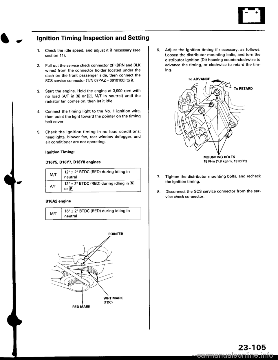
-lgnition Timing Inspection and Setting
1.Check the idle speed, and adjust it it necessary (see
section 'l '1 ).
Pull out the service check connector 2P (BRN and BLK
wires) from the connector holder located under the
dash on the front passenger side, then connect the
SCS service connector (T/N 07PAZ - 0010'100) to it.
Start the engine. Hold the engine at 3.000 rpm with
no load {A,/T in E or E. M/T in neutral) until the
radiator fan comes on, then let it idle.
Connect the timing light to the No. 1 ignition wire,
then point the light toward the pointer on the timing
belt cover.
Check the ignition timing in no load conditions:
headlights. blower fan, rear window defogger, and
air conditioner are not operating.
lgnhion Timing:
D15Y5. D16Y7, Dl6Yg engines
816A2 engine
MIT16" 12' BTDC (RED) during idling in
neutral
M/T12't 2" BTDC (RED) during idling in
neutral
l2'r 2" BTDC {RED) during idling in S
orE
POINTEB
RED MARK
23-105
ro ADVANCE -<;,
6. Adjust the ignition timing if necessary, as follows.
Loosen the distributor mounting bolts. and turn the
distributor ignition (Dl) housing counterclockwise to
advance the timing, or clockwise to retard the tim-
ing.
MOUNTING BOLTS18 N'm (1.8 kgfm, 13lblftl
Tighten the distributor mounting bolts, and recheck
the ignition timing.
Disconnect the SCS service connector from the ser-
vice check connector.
7.
Page 1635 of 2189

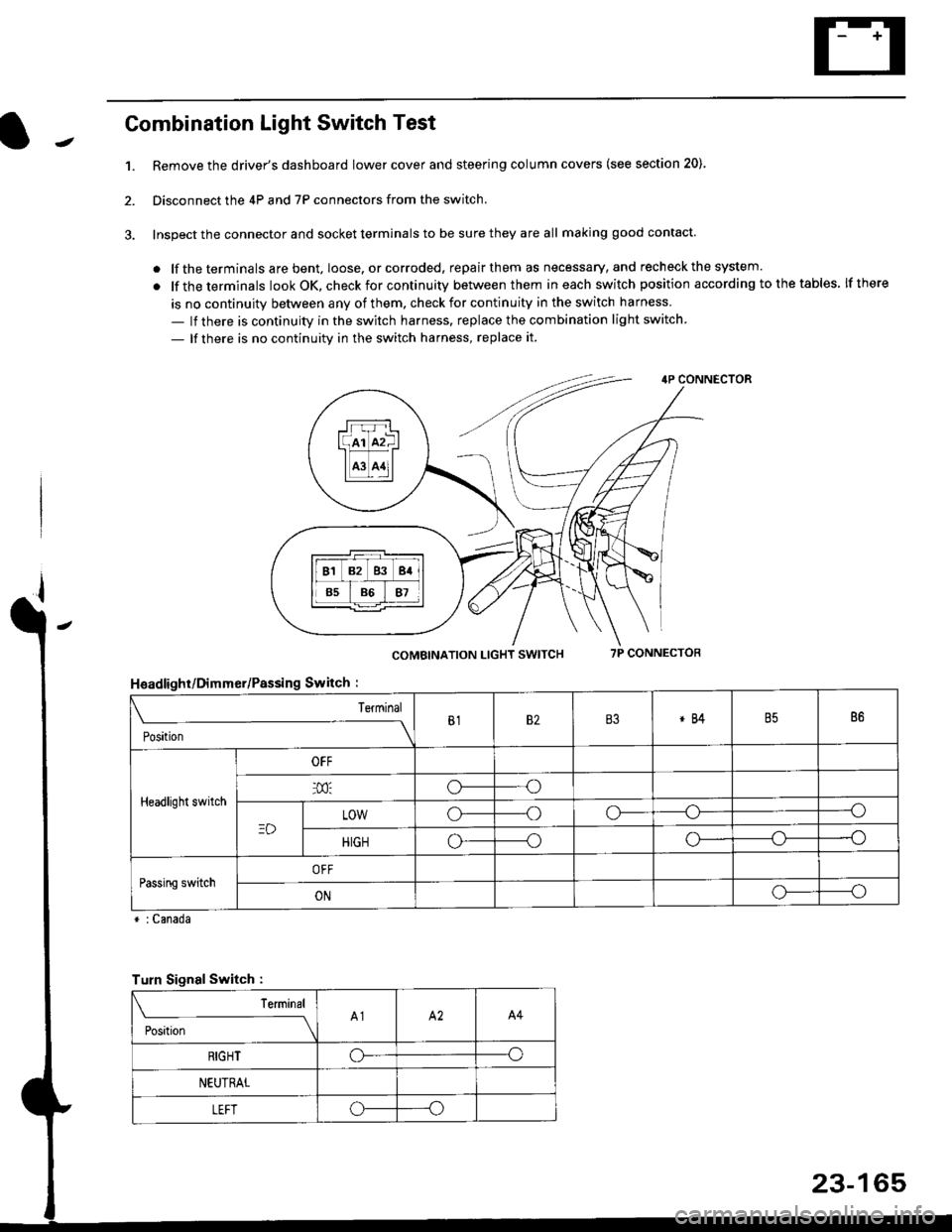
Combination Light Switch Test
1.Remove the driver's dashboard lower cover and steering column covers (see section 20)
Disconnect the 4P and 7P connectors from the switch.
Inspect the connector and socket terminals to be sure they are all making good contact
. lf the terminals are bent, loose. or corroded, repair them as necessary, and recheck the system.
. lf theterminals look OK, check for continuity between them ineach switch position according tothetables lfthere
is no continuity between any of them. check for continuity in the switch harness
- lf there is continuity in the switch harness. replace the combination light switch
- lf there is no continuity in the switch harness, replace it.
2.
4P CONNECTOR
COMBINATION LIGHT SWITCH7P CONNECTOR
HsadlighUDimmer/Passing Switch :
* : Canada
rrr r-l
l(rr mf ItffiTI A3 A11l
Terminal
Position
B182B3*84B586
Headlight switch
OFF
o---o
LOWo---oo-----o
HIGHo-----oo---o
Passing switchOFF
ONo-----o
Turn Signal Switch :
Teminal
;',*;----__\A1A2A4
RIGHToo
NEUTRAL
LEFToo
23-165
Page 1636 of 2189

Lighting System
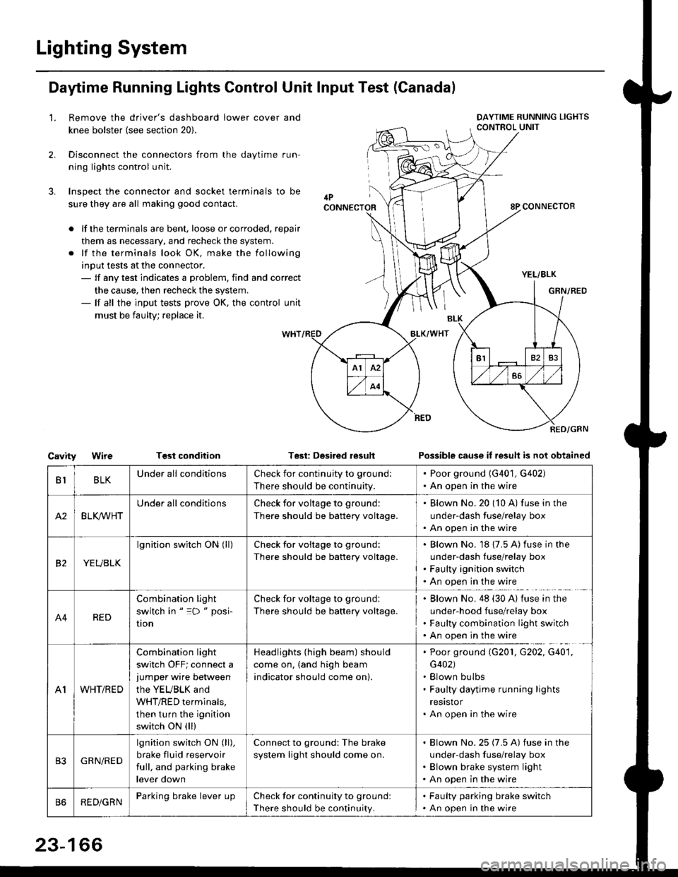
Daytime Running Lights Control Unit Input Test (Canadal
2.
3.
LRemove the driver's dashboard lower cover and
knee bolster (see section 20).
Disconnect the connectors from the daytime run-
ning lights control unit.
Inspect the connector and socket terminals to be
sure they are all making good contact.
lf the terminals are bent, loose or corroded. repair
them as necessary, and recheck the system.
lf the terminals look OK, make the following
input tests at the connector,- lf any test indicates a problem, find and correct
the cause, then recheck the system.- lf all the input tests prove OK, the control unit
must be faulty; replace it.
CavityWireTGst conditionTest: Desired resultPossible cause it result is not obtained
BLKU nderall conditionsCheck for continuity to g.ound:
There should be continuity.
. Poor ground (G401, G402). An open in the wire
A2BLK /VHT
Underall conditionsCheck for voltage to ground:
There should be battery voltage.
Blown No.20 (10 A) fuse in the
under-dash fuse/relay box
An open in the wire
etYEUBLK
lgnition switch ON (ll)Check for voitage to ground:
There should be battery voltage.
Blown No. 18 {7.5 A) fuse in the
under-dash luse/relay box
Faulty ignition switch
An open in the wire
A4RED
Combination light
switch in " =D " posi-
UOn
Check for voltage to ground:
There should be battery voltage.
Blown No. 48 (30 A) tuse in the
under-hood fuse/relay box
Faulty combination light switch
An open in the wire
A1WHT/RED
Combination light
switch OFF; connect ajumper wire between
the YEUBLK and
WHT/RED terminals,
then turn the ignition
switch ON (ll)
Headlights (high beam) should
come on, (and high beam
indicator should come on).
. Poor ground (G201, G202, G40'1,
G402). Blown bulbs. Faulty daytime running lights
resrstor. An open in the wire
GRN/RED
lgnition switch ON (ll),
brake fluid reservoir
full, and parking brake
lever down
Connect to ground: The brake
system light should come on.
Blown No.25 (7.5 A) fuse in the
under-dash f use/relay box
Blown brake system light
An open in the wire
REDiGRNParking brake lever LrpCheck for continuity to groundl
There should be continuity.
. Faulty parking brake switch. An open in the wire
23-166