Page 387 of 2189
PGM-FI System
(From page 11-117)
ls approx. 2 kPa ('15 mmHg, 0.6in.Hg) or less indicated?
Check for a short in ihe wire{MAP line)l1. Turn the ignition switch OFF.2. Disco n nect the ECM/pCMconnector D (16P).
3. Check for continuity betweenthe MAP sensor connector No.3terminal and body ground.
R6pair lhort in tha wire b€twaenECM/PCM {D3l .nd MAP !6ru0r.
Substitute a known-good ECM/PCM..nd recheck. normal MAPis indiceted, .eplsce lhe originalECM/PCM,
Manifold Absolute Pressure (MAp) Sensor('96 - 98 Models,'99 - 00 D16Y5 engine with M/Tl (cont,d)
MAP SENSOR 3P CONNECTOR IC1l1I
MAP(RED/GRNI
Wire side of femate;rminats
11-118
Page 389 of 2189
PGM-FI System
Manifold Absolute Pressure (MApl Sensor('99 - 00 Models except Dl6yS engine with M/T) (cont,dl
MAP SENSOn 3P CONNECTOB tcllilt
MAP(RED/GRNI
Wire side of female terminals
(From page 11 119)
Check for an open or shon in theMAP s€nsor:Check the MAP with the scantool.
ls approx. 2 kPa (15 mmHg,0.6 in.Hg) or less indicated?
Check tor a sho.t in lhe wire{MAP line):1. Turn the ignition switch OFF.2. Discon n ect the ECN4/pCN4connector C (31P).3. Check for continuity betweenthe MAP sensor connector No. 3terminal and body ground.
Repair short in the wire betweenECM/PCM {Cl7} and MAp s€n-sor.
Substitute a known-good ECM/PCM and rech6ck. lf no.mal MApis indicated, replace the o.iginalECM/rcM.
11-120
Page 394 of 2189

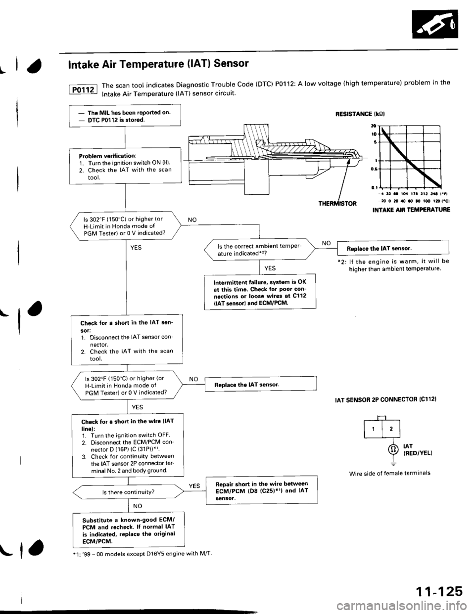
IIntake Air Temperature (lATl Sensor
The scan tool indicates Diagnostic Trouble Code {DTC) P0112: A low voltage (high temperature) problem in the
lntake Air Temperature (lAT) sensor circuit.
RESISTANCE IKOI
.-l
*2: lf the engine is warm, it will be
higher than ambient temPerature.
IAT SENSOR 2P CONNECTOR {C112)
. a2 .. toa rra rrl l:rt t.al20 0 20 ro ao ao too t2ot.cl
INTAXIE AIR TEMPEFATURE
IAT{RED/YEL)
termrnars
-+-r
I'l'l-_T-
I=
Wire side of female
The MIL has been Teported on.
DTC P0112 is stored.
Problem verification:1. Turnthe ignition switch ON 1ll)2. Check the IAT with the scan
tool-
ls 302'F (150"C) or hagher (or
H Limit in Honda mode ot
PGM Tester) or 0 V indicated?
ls the correct ambrent temper
ature indicatedi'�?Roolac€ tho IAT 3ensor.
lntermittent failure, svstom is OK
6t this tim€. Check for Poor Gon-
nections or loos€ wires st C112
{lAT.en3orl and ECM/PCM.
Check tor a shon in the IAT sen-
sor:1. Disconnect the IAT sensor con
nector.2. Check the IAT with the scan
tool.
ls 302"F (150'C)or higher (or
H'Limit in Honda mode of
PGM Tester) or 0 V indicated?
Ch6ck for s short in the wira (lAT
lin€):1. Turn the ignition switch OFF
2. Disconnect the ECM/PCM con-
nector D (16P) (C (31P))*'.
3. Check for continuity between
the IAT sensor 2P connector ler-
minal No. 2 and body ground.
Reoair short in the wire bstweenECM/PCM tD8 (c25)'1) and IAT
Substitute a known-good ECM/
PCM and recheck. It normel IAT
is indicated, replace the original
ECM/PCM.
* l: '99 - 0O models except Dl6Y5 engine with M/T-rf,
11-125
Page 398 of 2189

|.
'f
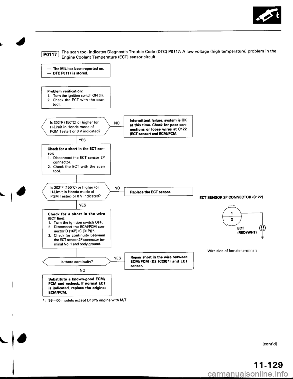
fD;r.tt The scan tool indicates Diagnostic Trouble Code (DTC) P0117: A low voltage (high temperature) problem in the|jg Engine Coolant Temperature (ECTI sensor circuit.
ECT SENSOR 2P CONNECTOR (C122I
Wire side of female terminals
Substitute . lnown-good ECM/PCM .nd rocheck. It normrl ECT
is indic.ted, replaco the original
ECM/PCM,
*:'99 -Oo models except D16Y5 enginewith M/T
(cont'd)
11-129
The MIL has been ,eported on.DTC ml 1 7 is storod.
Problom vorification:1. Turn the ignition switch ON (ll).
2. Check the ECT with the scantool.
Intermittont failulo, sy3tom it OK
at thk tim., Chock for Poor oon-n.ctions or loo!. wiraa at C122IECT 3en orl and ECM/FCM.
ls 302"F (150"C) or higher {orH-Limit in Honda mode ofPGM Tester) or 0 V indicated?
Check toJ a short in the ECT s.n-5('t:1. Disconnect the ECT sensor 2P
connector.2. Check the ECT with the scanrool.
ls 302"F (150"C) or higher {orH-Limit in Hond6 mode ofPGM Testerl or 0 V indicated?
Check for a 3hort in tho wiro
IECT linel:1. Turn the ignition switch OFF.2. Disconnect the ECM/PCM con-nector D (16P) (C {31P))*.3. Check for continuity betweenthe ECT sensor 2P conneclor ter-minalNo, 1 and bodyground.
B.gair short in the wiro bltweenECM/PCM (D2 (C261'l .nd ECT
.1,
Page 409 of 2189
PGM-FI System
(From page 11-139)
Check for a shon in the HO2S:1. Turn the ignition switch OFF.2. Disconnect the Primary HO2S(Sensor 1) 4P connector.3. Start the engine and let it idle.4. Check the Primary HO2S(Sensor 1)output voltage withthe scan tool,
Does it stay at 0.1 V or less?
Check for a short in lhe wire(PHO2S linel:1. Turn the ignition switch OFF.2. Disconnect the ECM/PCM con-nector D ('l6P).
3. Check for continuity betweenthe Primary HO2S lsensor 1)4P connector terminal No. 1and body ground.
Repair short in lhe wire b6tw6enECM/rcM (D7) and Primary llO2S{Sensor 1}.
Substitute a known-good ECM/PCM and recheck. ll symptom/indication goes awry, replaco theoriginal ECM/PCM.
Primary Heated Oxygen Sensor (Primary HO2S) (sensor 1l
('96 - 98 Models except Dl6Y5 engine with M/T) (cont'dl
PRIMARY HO2S lsonsor 1l ,tP CONNECTOR lC123l
Wire side of female terminals
11-140
Page 411 of 2189
PGM-FI System
Primary Heated Oxygen Sensor (Primary HO2SI (Sensor 1)
('99 - 00 Models except Dl6Y5 engine with M/T) (cont'd)
PRIMARY HO2S {S€oror 1} 4P CONNECTOR lc123l
PHO2S f----l,wHl_l:-f;-l
0ffi
_L
Wire side of female terminals
(From page 11 141)
Chock fo. a shori in the HO2S:1. Turn the ignition switch OFF.2. Disconnect the Primary HO2S(Sensor 1i 4P connector.3. Stan the engine and let it idle.4. Check the Primary HO2S(Sensor 1) output voltage withthe scan tool.
Does it stay at 0.5 V or less?Roplaco the HO2S (Sensor 1).
Check tor a short in the wire{PHO2S linel:1. Turn the ignition switch OFF.2. Disconnect the EcltI/PcM con-nector C {31P).3. Check for continuity betweenthe Primary HO2S lsensor 1)4P connector terminal No. 1and body ground.
ReDair shorl in the wi.e betweenECM/PCM (Cl61 and PrimaryHO2S (Sercor 11.
Substitute a known-good ECM/PCM and recheck. lf symptom/indication goes away, replace theoriginal ECM/PCM.
11-142
Page 416 of 2189

Check the ECM input vottage {lP-/
VS- lino):1. Turn the ignition switch OFF.
2 Turn the ignition switch ON (ll)
3. Measure voltage between
ECM connector terminals C24
Ch.ck the ECM:
1. Turn the ignition switch OFF
2. Disconndct ECM connector C
{31P){rom the ECM.
3. Check lor continuity between
body ground and ECM con
nector terminal C24
ls there more than 0.5 V?
- Repair open in the wire
betw€en ECM {C2{l and Pri-
ma.y HO2S {S€nsor 1 l.- Substitute a known-good ECM
and recheck. It symptom/indi
cation goes away. replace the
odginal ECM.
Check to. r short in the wi.e {lP-/
VS- lin6l:1. Disconnect the 8P connector
from the Primary HO2S lsen-
sor 1).2. Check tor continuity between
body ground and ECM connec-
tor terminal C24
Ropair short in the wire bstween
the Primary HO2S lsensor 1) and
ECM (C24).
Check the ECM output voltage
{VS+ linel:N4easure voltage between ECM
connectorterminals C25 and D11.
Check for a short in the wire (VS+
line):1. Turn the ignition switch OFF.
2. Disconnect ECM connector C
{31P) Irom the ECM.
3. Check {or continuity between
body ground and ECM con
nector terminal C25.
ls there mote than 0.5 V?
ECM CONNECTORS
lFrom page'11-146)c (31PlD {15P)
tP-/vs- tREolfemale termrnals
sG2(GRN/BLKI
(cont'd)
11-147
I23a68910
111213la15t6'171622
232a25272a2930
O rP-/vs-:Z taeot
,l23a55I910
1112131a151617t822
232125212AE30
0) {REDr
23a518910
l11213ta'15't6171822
2321E272A2930
[]) vs*I rwsrt
(To page 11- 148)(To page 11 148)
Page 417 of 2189

PGM-FI System
Primary Heated Oxygen Sensor (Primary HO2SI (sensor l)
(Dl6Y5 engine with M/T) (cont'd)
(From page 1l-147)(From page 11 147)
(To page 11 149)
{GRN/BLK}
(GRN/8I-K}
(To page 11-149)
11-148
Substitute a known-good ECMand rechock. tf symptom/indicr-tion goes away, replace the origi-nalECM.
Check for a short in the wire llP+lin6):1. Disconnect the 8P connectorIrom the Primary HO2S (Sen-
sor 1).2. Check tor continuity betweenbody ground and ECM connec-tor terminal C25.
Repair short in the wiro botweenthe Primarv HO2S {Sensor 1} andECM {C25}.
Replace th€ Primary HOzS {Sen-sor 11.
| 2 3ra1a9to
tl 12t516111a
p ffi;r, w''.""i0"or.I lemate lerml
ls there more than 5.0 V?check the EcM:1. Turn the ignition switch OFF.2. Disconnect the 8P connectorfrom the Primary HO2S (Sen-
sor 1).3. Turn the ignition switch ON (ll).4. Measure voltage between ECN4connector C25 and D11.
ls there more than 5.0 V?
Check the ECM input voltage llP-/vS-linel:1. Start the engine. Hold theengine at 3,000 rpm with noload (transmission in neutral)untilthe radiator fan comes on,then let it idle.2. Measure voltage between ECMconnector terminals C24 andDt1.
Subslitute a known-good ECMand rgcheck. It symptom/indica-tion goes away, repl.ce the origi-nal ECM.
ls there 2.6 2.8 V?Check th6 ECM output voltage(VS+ linel:Measure voltage between ECMconnector terminals C25 and D11.
7a9t0It 12t3t6'11ta
VS+{WHT}sG2
235
,9 ,101l12
l3'tat515
1 2i35a9t0't2'ttt5ttrl22
VS+{WHT)sG2
23
6lt9ll1315