1997 HONDA CIVIC Engine coolant temperature
[x] Cancel search: Engine coolant temperaturePage 520 of 2189

\J
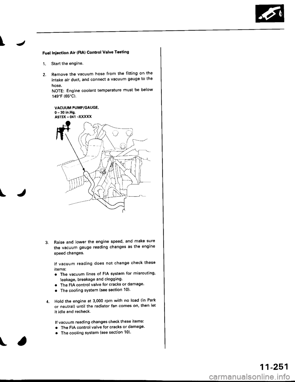
Fuol Iniection Air {FlA) Contlol Valve T$ting
1. Start the engine.
2. Remove the vacuum hose from the fitting on the
intake air duct, and connect a vacuum gauge to the
nose.
NOTE: Engine coolant temperature must be below
149"F (65"C).
VACUUM PUMP/GAUGE,
0-30 in.Hg.A973X - 041 -XXXXX
Raise and lower the engine speed, and make sure
the vacuum gauge reading changes as the engine
speed changes.
lf vacuum reading does not change check these
rtems:
. The vacuum lines of FIA system for misrouting,
leakage, breakage and clogging.
. The FIA controt valve for cracks or damage
. The cooling system (see section 10).
Hold the engine at 3,OOO rpm with no load (in Park
or neutral) until the radiator fan comes on, th€n let
it idle and recheck.
lf vacuum reading changes check these items:
a The FIA control valve for cracks or damage.
. The cooling system (see section 10).
11-251
Page 536 of 2189

1\
Evaporative Emission (EVAPI Controls
Description
The evaporative emission controls are designed to minimize the amount of fuel vapor escaping to the atmosphere. The
system consists of the foliowing components:
A. Evaporative Emission (EVAP) Control Canisto]
An EVAP control canister is used for the temporary storage of fuel vapor until the fuel vapor can be purged from the
EVAP control canister into the engine and burned.
B. Vapor Purge Control System
EVAP control canister purging is accomplished by drawing fresh air through the EVAP control canister and into a port
on the intake manifold. The purging vacuum is controlled by the EVAP purge control solenoid valve.
I'96 D16Y5 engine,'96 Dl6Y7 engine,'96 D16Y8
engine (sedan),'97 D16Y5 engine,'97 D16Y7
engine (couper KA, KC models, sedan: KA, Kc'
KL iDX) models, hatchback: all models), '97
D 16Y8 engine (sedan: KA, KC models)l
I'96 D16Y8 engine (coupe),'97 D16Y7 engine
(coupe: KL model, sedan: KL (LX) model)"97
D16Y8 engine (coupe: all models, sedan: KL model)'98-all models,'99-all models,'00-all modelsl
I
c.
D.
or
l'lc COMPRESSOR CLUTCH ON
and
INTAKE AIR TEMPERATURE ABOVE 160"F (41'C)
Fuel Tank Vapor Control System
When fuel vapor pressure in the fuel tank is higher than the set value of the EVAP two way valve, the valve opens and
regulates the flow of fuel vapor to the EVAP control canister.
Onboard Refueling Vapor Recovery (ORVRI System {'99 - 00 models}
During refueling. the oRVR {onboard Refueling Vapor Recovery) vent shut valve opens with the pressure in the fuel
tank. and feeds the fuel vapor to the EVAP control canister.
t(cont'd)
11-267
EVAP PURGE CONTROL SOLENOID VALVE DUTY CON-
TROLLED AFTER STARTING ENGINE
ENGINE COOLANT TEMPERATURE ABOVE 154'F {68"C)
INTAKE AIR TEMPERATURE ABOVE 32'F (O'C)
and
VEHICLE SPEED ABOVE O MILE (O KM/h}
ENGINE COOLANT TEMPERATURE ABOVE 154'F (68'C)
Page 558 of 2189

\
EVAP CONTROLCANISTER VENT SHUTVALVE 2P CONNECTOR IC141I
Wire side of temale terminals
ECM,/PCM CONNECTORS
tG1IBLK/WHT}
A973X -
0/r1 - XXXXX
Wire side of femaletermrnats
\
?,T-t
fl
VACUUMPUMP/GAUGE, 0 -30 in.Hg
\(cont'd)
11-289
{From page l1 288}
{To page 11-290)
Ch€ck the vac[um when cold:1, Disconnect the vacuum hoseshown from the EVAP controlcanister and connect a vacuumgauge to the hose.2. Start the engine and allow it
to idle.NOTEi Engine coolant temperature must be below 154"F(68'C) or Ay'C switch OFF.3. Ouickly raise the engine speedto 3,000 rpm.
(From page 11-288)
Check for an open in tha wire(lGt linol:1. Turn the ignition switch OFF.2. Disconnect the 2P connectorfrom the EVAP control canis-ter vent shut valve.3. Turn the ignition switch ON lll).4. Measure voltage between theEVAP control canister vent shut
valve 2P connector terminalNo.2 and bodyground.
Repair open in the wire betweenthe EVAP control canister ventshut valve .nd the No. 15 ALTER-NATOR SP SENSOR {7.5 A)fu3e.
ls there battery voltage?
Ch€d( for an op€n in the wiie IVSVlinel:1. Turn the ignition switch OFF.
2. R€connect the 2P connectorto the EVAP control canistervent shut valve,3. Turn the ignition switch ON (ll).
4. Measure vo ltage betweenECM/PCM connector termi-nals A4 and 82.
Repair open in the wire bctweenthe EVAP control canistor ventshut valve and lhe ECM/PCM{44t.
ls there battery voltage?
Rcolaco tho EVAP control canis.t6r vent shut valvo.
a t32P)
-
Page 693 of 2189

GRADE LOGIC CONTROL SYSTEM
How it works:
The pCM compares actual driving conditions with driving conditions memorized in the PCM, based on the input from the
vehicle speed sensor, the throttle position sensor, the barometoric pressure sensor, the engine coolant temperature sensor,
the brake switch signal, and the shift lever position signal, to control shifting while a vehicle is ascending or descending a
slope, or reducing speed.
SIGNALS OETECTED
O.iving Resi3lence
Judgemenl ot Conirolling Arca
. Ascending mod€
lFuzzy loqicl. Gradual Ascending mode' Ste€p Ascending mode. Oescending mode. Gr.du.l Descending mode. Steep D6cending mode
14-15
Page 752 of 2189

Electrical Troubleshooting ('96 - 98 Models)
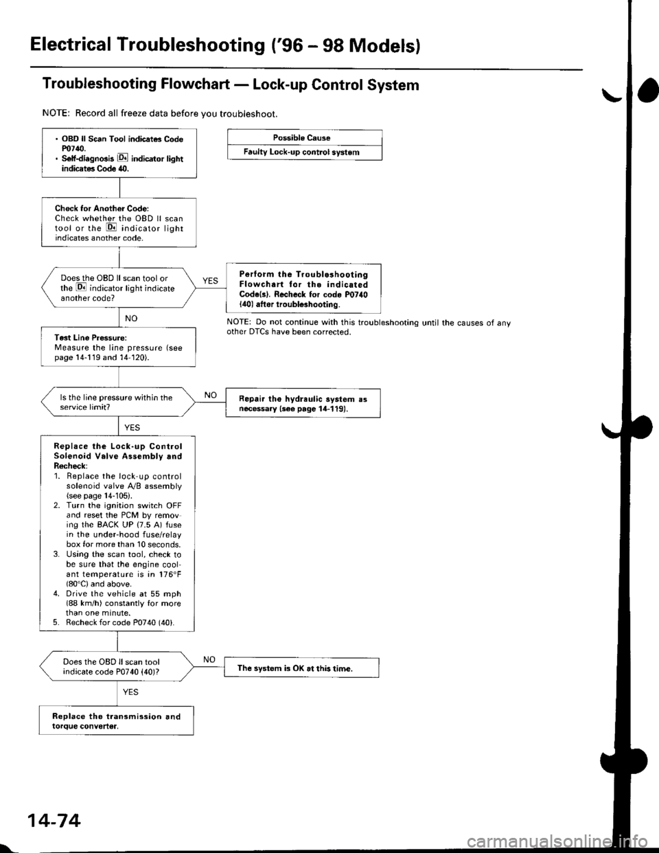
Troubleshooting Flowchart - Lock-up Control System
NOTE: Record all freeze data before vou troubleshoot.
Possible Cause
Faulty Lock-up cont.ol system
NOTE: Do not continue with this troublesnoonnoother DTCS have been corrected.until the causes of any
. OBD ll Sc6n Tool indicatG Codem7{0.. Self-diagnosis E indicator lightindicates Code 40.
Check tor Another Code:Check whether the OBD ll scantool or the E indicato, lightindicates another code.
Perform lhe Troublo3hooiingFlowchart tor the indicatedCode(s). Recheck for cod. P07il0lilol aftor iroubl€3hooting.
Does the OBD ll scan tool orthe E indicator light indicateanother code?
Tast Line Pressure:Measure the line pressure (seepage 14-119 and 14-120).
Repair tho hydreulic aystem a3necessary {3ee page 14-119).
Replace the Lock-up ControlSolenoid Valve Assembly andR6check;1. Beplace the lock up controlsolenoid valve Ay'B assembly(see page 14-105).2. Turn the ignitaon switch OFFand reset the PCM by removing the BACK UP (7.5 A) fusein the underhood fuse/relaybox for more than 10 seconds,3. Using the scan tool, check tobe sure that the engine coolant temperature is in 176'F(80'C) and above.4. Drive the vehicle at 55 mph(88 km/h) constantly for morethan one minute.5. Recheck for code P0740 (40).
Does the OBD ll scan toolindicate code P0740 {40)?The systom k OK at this time.
l'.
14-74
Page 884 of 2189

Description
Electronic Control System ('99 - 00 Modelsl (cont'dl
Grade Logic Control System
How it works:
The PcM compares actual driving conditions with memorized driving conditions. based on the input from the vehiclespeed sensor, the throttle position sensor, the manifold absolute pressure sensor, the engine coolant temperature sensor,the brake switch signal, and the shift lever position signal, to control shifting while the vehicle is ascending or descendinga slope.
Ascending Control
When the PCM determines that the vehicle is climbing a hill in E position, the system selects the most suitable shiftschedule (pulley ratio) according to the magnitude of a gradient. so the vehicle can run smooth and have more powerwhen needed. There are three ascending modes with different shift schedules according to the magnitude ot a gradient inthe PCM.
Descending Control
when the PCM determines that the vehicle is going down a hill in E position. the system selects the most suitable shiftschedule (pulley ratio) according to the magnitude of a gradient. This, in combinstion with engine braking, achievessmooth driving when the vehicle is descending, There are three descending modes with different shift schedules accord-ing to the magnitude of a gradient in the PCM.
L
14-206
Page 970 of 2189

Start Clutch Control@
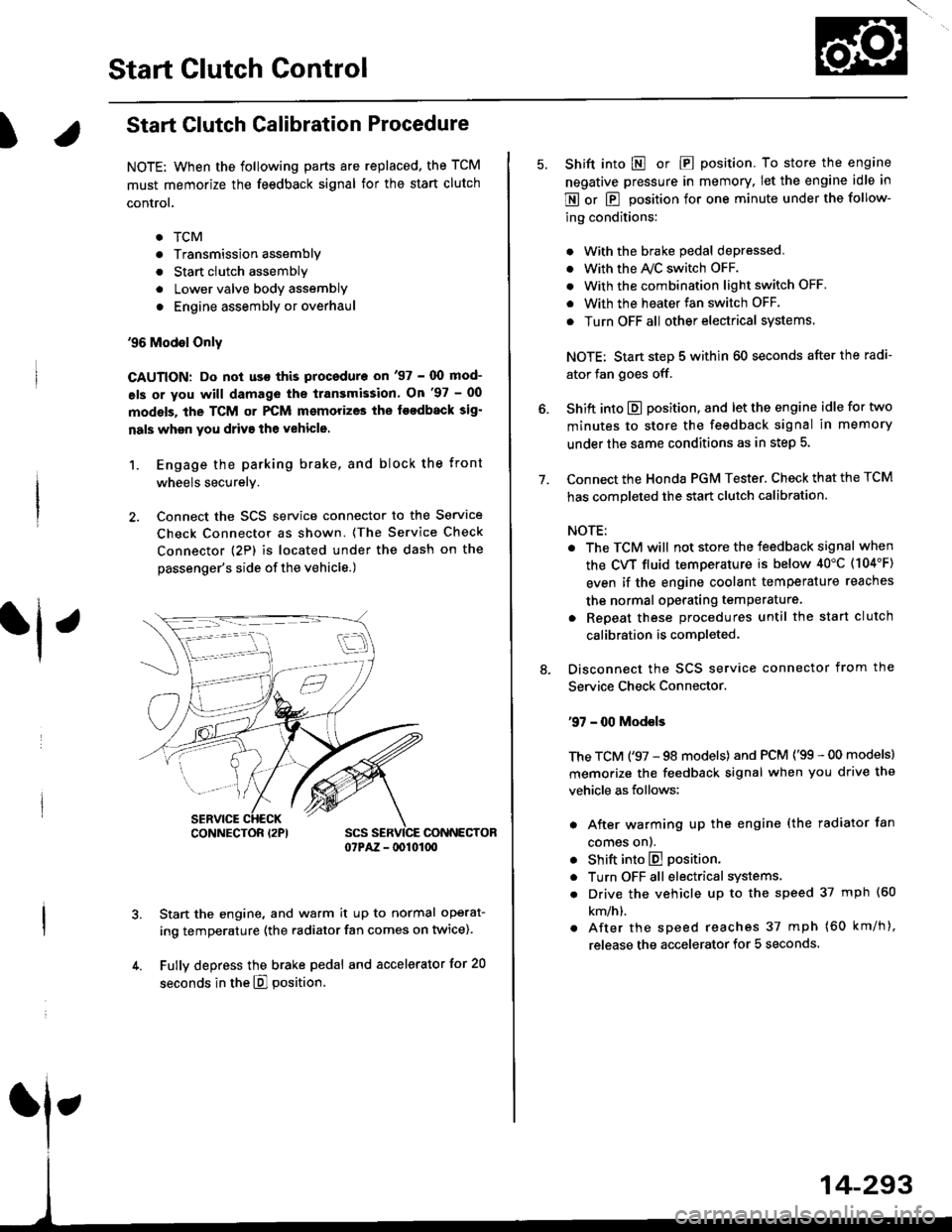
T
Start Clutch Calibration Procedure
NOTE: When the following parts are replaced, the TCM
must memorize the feedback signal for the start clutch
control.
. TCM
. Transmissionassembly
. Stan clutch assembly
. Lower valve bodv assembly
. Engine assembly or overhaul
'96 Model Only
CAUTION: Do not uso this procsdure on'97 - (X) mod-
els or you will damage the transmission. On '97 - 00
models, the TCM or PCM memorizes ths loodback sig'
nals when you drive the vehicle.
1. Engage the parking brake, and block the front
wheels securely.
2. Connect the SCS service connector to the Service
Check Connector as shown. (The Service Check
connector (2P) is located under the dash on the
passenger's side of the vehicle.)
CONNECTOR07PAZ - lDl01(xt
Start the engine, and warm it up to normal operat-
ing temperature (the radiator fan comes on twice).
Fully depress the brake pedal and accelerator for 20
seconds in the E] position.
rl ,
CONNECTOR I2PI
14-293
7.
Shift into E o|. E position. To store the engine
negative pressure in memory. Iet the engine idle in
E or E position for one minute under the follow-
ing conditions:
. With the brake pedal depressed,
. with the y'\/c switch oFF.
. With the combination light switch OFF.
. With the heater fan switch OFF.
. Turn OFF all other electrical systems
NOTE: Start step 5 within 60 seconds after the radi-
ator fan goes off.
Shift into E position, and let the engine idle for two
minutes to store the feedback signal in memory
under the same conditions as in step 5.
Connect the Honda PGM Tester. Check that the TCM
has completed the start clutch calibration.
NOTE:
. The TCM will not store the feedback signal when
the CVT fluid temperature is below 40"C (104'F)
even if the engine coolant temperature reaches
the normal operating temperature.
. Repeat these procedures until the start clutch
calibration is completed-
Disconnect the SCS service connector from the
Service Check Connector.
'97 - 00 Models
The TCM ('97 - 98 models) and PCM ('99 - 00 models)
memorize the feedback signal when you drive the
vehicle as follows:
. After warming up the engine (the radiator fan
comes onl.
. Shift into E position.
. Turn OFF all electrical systems,
. Drive the vehicle up to the speed 37 mph (60
km/h).
. After the speed reaches 37 mph (60 km/h),
release the accelerator for 5 seconds.
Page 1486 of 2189

Connector ldentification and Wire Harness Routing
Engine Wire Harness lD16Y5, D16Y8 enginss): '96 - 98 models
Connector or
Torminal
Numbsr of
CavitissLocationConnects toNot€s
c 101c102c103c104c104c105c106c107c108c 109c110c111c112c113c114c115c116cl17c118c119c120cl21
c122c123cl23c124
c125
c127c12Ac129c130c131c132c 133c134c135
c136
c138c139c140c 141c142c 143c144cl44c145c'146cl47
10
1
22
14l4322l0I
2
2
2
2120
3l
14
14
1222
2
2
22
Left side of engine compartmentMiddle of engineMiddle of engineLeft side of engine companmentLeft side of engine compartmentMiddle of engineMiddle of engineMiddle of engineMiddle of engineMiddle of enginefvliddle of engineMiddle of engineMiddle of engineMiddle of engineMiddle of engineMiddle of engineMiddle of engineLeft side of engine compartmentMiddle of engineMiddle of engineMiddle of engineMiddle of engine
Middle of engineMiddle of engineMiddle of engineMiddle of engineMiddle of engineMiddle of engineMiddle of engineMiddle of engineMiddle of engineRight side of engine companmentBehind right kick panelUnder right side of dashUnder riOht side of dashUnder right side of dashUnder right side of dashUnder right side of dashUnder right side of dash
Under right side of dash
Under right side of dash
Middle of engineMiddle ot enginel iddle of engineMiddle of engineMiddle of ongineMiddle of engineLeft side of engine compartmentMiddle of engineMiddle of engineRight side of engine compartmentRight side of engine compartmentRight side of engine compartment
USACanada
Afi
USA
-' (A/r)
Main wire harness (C303)Crankshaft speed fluctuation (CKF) sensorEngine oil pressure switchAlternatorAlternatorNo. 'l fuel injectorNo. 2 fuel injectorNo.3 fuel injectorNo. 4 fuel injectorIAC valveThrottle position (TP) sensorl\4anifold absolute pressure (MAP) sensorIntake air temperature (lAT) sensorPower steering pressure {PSPI switchEVAP purge control solenoid valveJunction connectorJunction conn€ctorVehicle speed sensor {VSS}Countershaft speed sensorEngine coolant temp€rature (ECT) switch ADistributorEngine coolant temperature (ECT) sendingunrtEngine coolant temperature (ECT) sensorPrimary HO2S (sensor'l)Primary HO2S (sensor 1)Back-up light switchLock-up control solenoid valveSecondary HO2S (sensor 2)Mainshaft speed sensorLinear solgnoid valveShift control solsnoid valveStarter solenoidJunction connectorMain wire harnesE (C446)ECM/PCMPCMECMiPCMECM/PCMMain wire harness (C305)
Main wire harness (C305)
Main wire harness (C305)
Knock sensor (KS)IAC valveVTEC solenoid valveVTEC pressure switchEVAP control canister vent shut valveEGR control solenoid valveSecondary gear shaft speed sensorEGR valveEGR valveDrive pulley speed sensorSolenoid connector {CVT)Driven pulley speed sensor
*, (M/T)M/T*" INT\
*, tAtf)
NT:'96 model*,(A,/T):'97 - 98mooets
moqets
M/T
-1 (l,/T)*, (A,/T)-,(4,/T)*1 {M/T)*, (A,/T)*1 (CW)*, (A,T)
T101r102Left side of engine companmentRight side of engine companmentAlternatorUnder-hood fuse/relay boxG 101Middle of engineEngine ground, via engine wire harness
2
*1: Dl6Y5 engine*2: D16Y8 engine*3: D16Y5 (Ay'T), D16Y8 engines
3-16