Page 1680 of 2189
Power Mirrors
Funstion Test (cont'dl
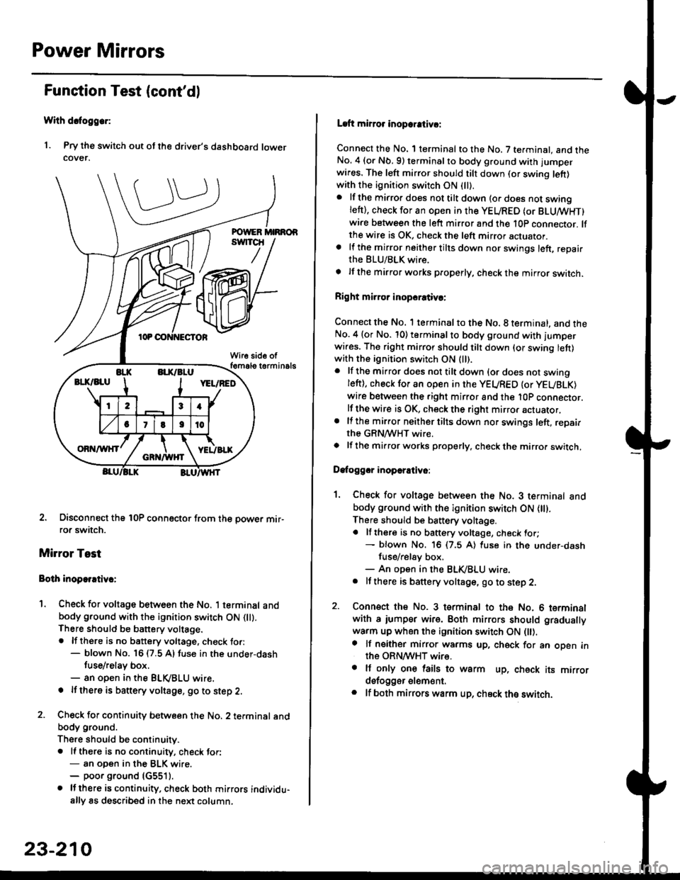
With dcfoggcr:
1. Pry the switch out ot the driver's dashboard lowercover.
2. Disconnect the 10P coonector from the oower mir-ror switch.
Mirror Test
Bolh inoparrtiv.:
1. Check for voltage between the No. 1 terminal andbody ground with the ignition switch ON flt).There should be battery voltage.. lf there is no battery voltage, check to.:- blown No. 16 (7.5 A) fuse in the under-dash
tuse/relay box.- an open in the BLVBLU wrre.
! lf thero is banery voltage, go to step 2.
2. Check for continuity b€tween the No. 2 terminal andbody ground.
There should be continuitv.. ll there is no continuity, check tor:- an open in the BLK wire.- poor ground (G5511.
. lJthere is continuity. check both mirrors individu-ally 8s described in the next column,
23-210
Laft mirror inopcrativ!:
Connect the No. 1 terminal to the No. 7 terminal. and theNo. 4 (or Nb.9) terminalto body ground with jumper
wires. The left mirror should tilt down (or swing left)with the ignition switch ON (ll).
. lf the mirror does not tilt down (o. does not swinglett), check for an open in the YEURED (or BLUMHT)wire between the left mirror and the 10p connector. lfthe wire is OK, check the left mirror actuator.a lf the mirror neither tilts down nor swings left, repairthe BLU/BLK wire.
t lf the mirror works properly, check the mirror switch.
Right mi.ror inopcrativc:
Connect the No. 1 terminal to the No. 8 terminal, and theNo.4 (or No. 10) terminalto body ground with l'umperwi.es. The right mirror should tilt down (or swing lett)with the ignition switch ON (ll).
. lf the mirror does not tilt down {or does not swingleft), check for an open in the YEURED {or YEUBLK)
wire between the right mirror and the l0P connector.lf the wire is OK, check the right mirror actuator,. lf the mirror neither tilts down nor swings left, repairthe GRN/WHT wire.o lf the mirror works properly. check the mirro. switch,
Dafoggcr inoperEtivo:
1. Check for voltage between the No. 3 terminal andbody ground with the ignition switch ON (||).
There should be battery voltage.a lf there is no battery voltage, check for;- blown No. 16 (7.5 A) luse in the under-dash
fuse/rel8y box,- An open in the BLK,iBLU wire.. It there is battery voltage, go to step 2.
2. Connsct the No. 3 tsrminal to the No. 6 terminalwith a iumpsr wire. Both mirrors should gradually
warm up when the ignition switch ON flt).a lf neither mirror warms up, check for an open inthe ORN/WHT wire.. It only on€ lails to warm up, check its mirrordsfogger elem6nt.. lf both mirrors warm up, check ths switch.
Page 1682 of 2189
Power Mirrors
Power Mirror Test
1. Pry out the cover panel (see section 20).
Terminalside ofmale terminals
*: Canada '99 - 00 models
Disconnect the 8P connector from the power mirror.
Check actuator operation by connecting power and
ground according to the tables.
Dofogger Test:
4. Check for continuity between the No. 3 and No. 4
terminals of the 8P connector.
There should be continuity.
COVER
L___r"'ry1Position67I
TILT UPo@
TILT DOWN@
SWING LEFTo@
SWING RIGHT@
23-212
Mirror Actuator Replacement
(Donnelly Typel
'1. Remove the power mirror from the door {see sec-
tion 20). and disconnect the 8P connector.
2. Remove the mirror base cover from the mirror
housing.
MIRROR HOLDER
Remove the mirror holder from the mirror housing.
Gently pull it out by hand.
Remove the three screws from the actuator and the
two screws from the bracket at the base of the
assemory.
BRACKET
5. Remove the bracket from the housinq.
4.
MIRROR HOUSING
Page 1687 of 2189
Wiper/Washer Switch Test
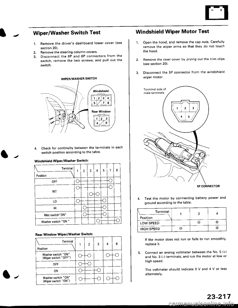
Remove the driver's dashboard lower cover {see
section 20).
Remove the steering column covers.
Disconnect the 8P and 6P connectors from the
switch, remove the two screws, and pull out the
switch.
4. Check tor continuity between the terminals in each
switch position according to the table
Windshield Wiper/Washer Switch:
Terminal
Position \
12357I
OFFoo
INTo-o
oo
LOoo
HIoo
l\4ist switch"0N"oo
Washer switch "0N "oo
Rear Window WiPer/Washer Switch:
I Terminal
'i"*
--J2346
Washer switch "0N"
(Wiper switch "OFF"lo--oo--o
OFFo--o
ONo--o
Washer switch "0N"
{Wiper switch "0N")o--oo--o
1.
WIPER/WASHER SWITCH
Windshield:
l1 2 314 |
li.l7a,lil
Rear Window:
11 z 3l
lT-,rtl
Windshield Wiper Motor Test
1.Open the hood, and remove the cap nuts. Carefully
remove the wiper arms so that they do not touch
the hood.
Remove the cowl cover by prying out the trim clips
(see section 20).
Disconnect the 5P connector lrom the windshield
wiper motor.
Test the motor by connecting battery power
ground according to the table.
lf the motor does not run or fails to run smoothiy,
replace it.
5. Connect an analog voltmeter between the No. 5 {+)
and No.3 {-) terminals. and run the motor at low or
high speed.
The voltmeter should indicate 0 V and 4 V or less
alternately.
Terminal
i**l*-
-_\14
LOW SPEEDo@
HIGH SPEEDo@
23-217
Page 1688 of 2189
Wipers/Washers
Rear Wiper Motor Test (Hatchback)
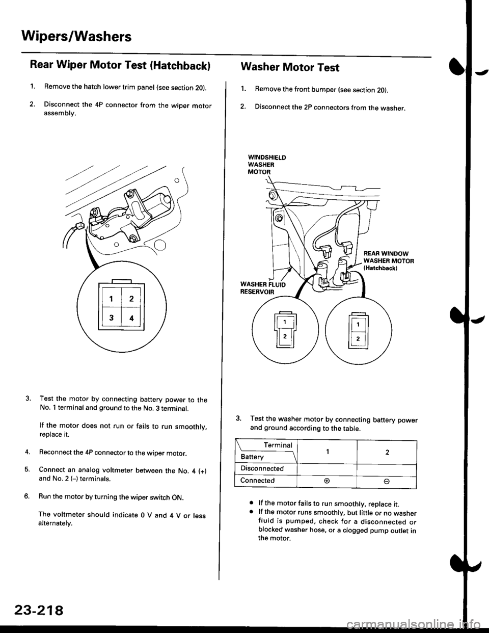
1.Remove the hatch lower trim panel (see section 20).
Disconnect the 4P connector from the wiper motorassemDry,
Test the motor by connecting battery power to theNo. 1 terminal and ground to the No. 3 terminal.
lf the motor does not run or fails to run smoothly,reptace rI.
Reconnect the 4P connector to the wiper motor.
Connect an analog voltmeter between the No. 4 (+)
and No.2 (-)terminals,
Run the motor by turning the wiper switch ON.
The voltmeter should indicate 0 V and 4 V or lessalternately.
23-218
1.
Washer Motor Test
Remove the front bumper (see section 20).
Disconnect the 2P connectors from the washer,
a
a
lf the motor fails to run smoothly, replace it.lf the motor runs smoothly. but little or no wasnerfluid is pumped. check for a disconnecr€o orblocked washer hose, or a clogged pump outlet inthe motor.
REAR WINDOWWASHER MOTOR(Hatchbackl
WASHER FLUIORESERVOIR
3. Test the washer motor by connecting battery power
and ground according to the table.
L f:,ry1Battery1
Disconnected
Connected@
Page 1699 of 2189
CavityWireTest conditionTest: Desired resultPossible caus€ if result is not obtainsd
BLK
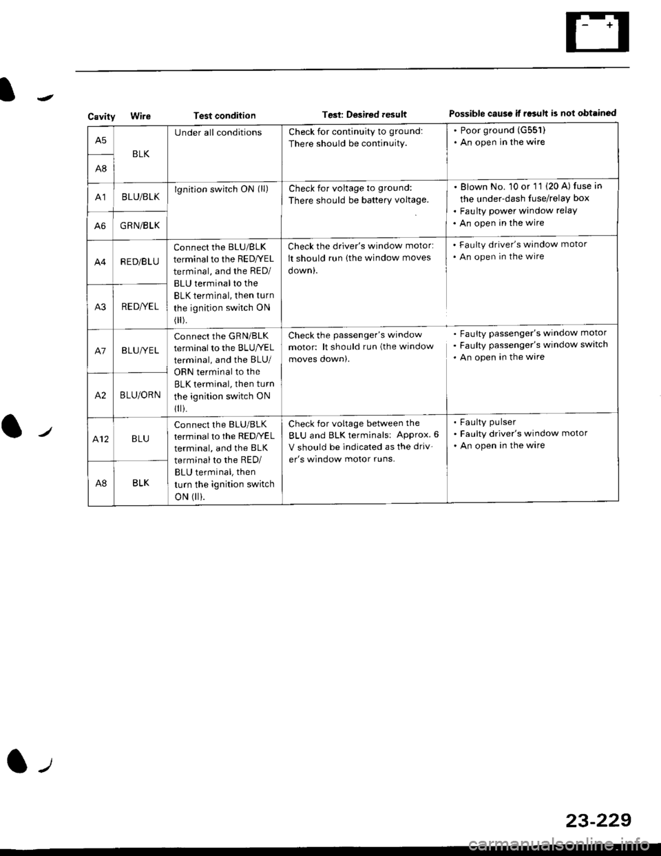
U nderall conditionsCheck for continuity to ground:
There should be continuity.
. Poor ground (G551)
. An open in the wire
A8
A']BLU/BLKlgnitlon switch ON (ll)Check for voltage to ground:
There should be batterY voltage.
Blown No. 10 or '11 (20 A) fuse in
the under-dash fuse/relay box
Faulty power window relay
An open in the wireA6GRN/BLK
R ED/B LU
Connect the BLU/BLK
terminal to the RED/YEL
terminal, and the RED/
BLU terminal to the
BLK terminal, then turn
the ignition swilch ON
(
).
Check the driver's window motor:
It should run (the window moves
oown,.
Check the passenger's window
motor: lt should run (the window
moves qown,.
Check for voltage between the
BLU and BLK terminals: APProx. 6
V should be indicated as the driv-
er's window motor runs.
Faulty driver's window motor
An open in the wire
Faulty passenger's window motor
Faulty passenger's window switch
An open in the ware
Faulty pulser
FaLilty driver's window motor
An open in the wire
A3RE D/YE L
A7BLUI/E L
connect the GRN/BLK
terminal to the BLUryEL
terminal, and the BLU/
ORN terminal to the
BLK terminal, then turn
the ignition switch ON
1
i.
A2BLU/ORN
412BLU
Connect the BLU/BLK
terminal to the REDI/EL
terminal, and the BLK
terminal to the RED/
BLU terminal, then
turn the ignition switch
oN (|| ).
A8BLK
23-229
Page 1701 of 2189
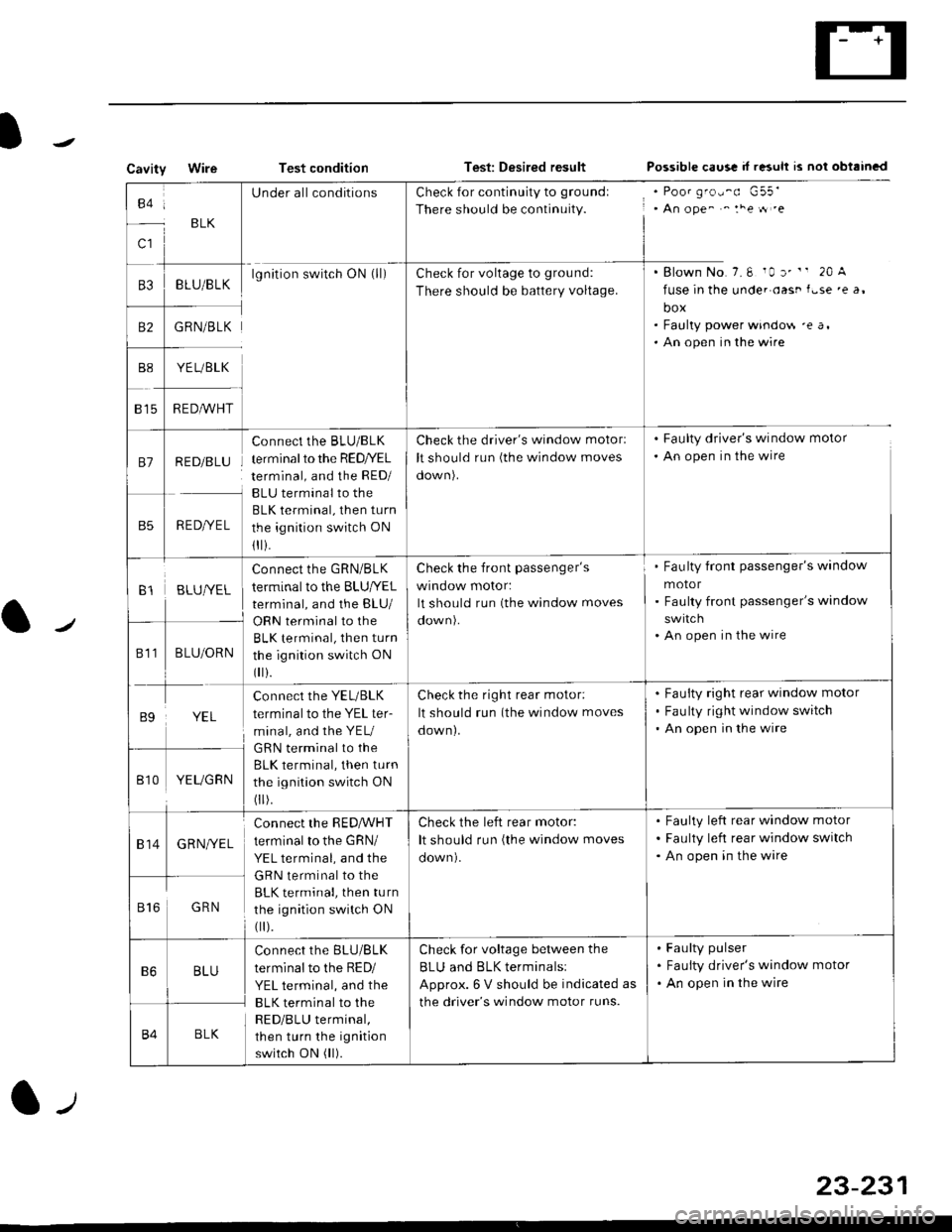
CavityWireTest conditionTest: Desired resultPossible caus! d r"suh rs nol obtrincd
to:
c1
BLK
UnderallconditionsCheck for continuity to groundl
There should be continuity., An ope^ ^ :he tt .e
. Blown No.7.6 10 r' " 20 A
fuse in the unde. oast f.se 'e a,
box. Faulty power windo$ 'e a,. An open in the wire
B3BLU/BLKlgnition switch ON (ll)Check for voltage to grou nd:
There should be battery voltage.
B2GRN/BLK
YE L/BLK
R EDA/VHT815
81RED/BLU
RED/YEL
Connect the BLU/BLK
terminal to the RED/YEL
terminal, and the RED/
BLU terminal to the
BLK terminal, then turn
the ignition switch ON
1I i.
Check the driver's window motorl
It should run (the window moves
oown).
. Faulty driver's window motor
. An open in the wire
B1BLUIVEL
Connect the GRN/BLK
terminal to the BLU|YEL
terminal, and the BLU/
Check the front passenger's
wrnoow motor:
It should run (the window moves
Fau lty front passenger's window
motor
Faulty front passenger's window
An open in the wire
811BLU/ORNBLK terminal, then turn
the ignition switch ON
0 r).
B9YEL
connect the YEL/BLK
terminal to the YEL ter-
minal, and the YEU
GRN terminal to the
BLK terminal, then turn
the ignition switch ON
0 r).
Check the right rear motor:
It should run (the window moves
down).
Fauity right rear window motor
Fau lty right window switch
An open in the wire
Bt0YEUGRN
814GRNI/EL
connect the RED,ryVHT
terminal to the GRN/
YEL terminal, and the
GRN terminal to the
BLK terminal, then turn
the ignition switch ON
0 r).
Check the left rear motor:
It should run (the window moves
Faulty left rear window motor
Faulty left rear window switch
An open in the wire
816GRN
B6BLU
Connect the BLU/BLK
terminal to the RED/
YEL terminal, and the
BLK terminal to the
RED/BLU terminal,
then turn the ignition
switch ON (ll).
Check for voltage between the
BLU and BLK terminalsl
Approx. 6 V should be indicated as
the driver's window motor runs.
Faulty pulser
Faulty driver's window motor
An open in the wire
B4BLK
23-231
Page 1703 of 2189
Driver's Window Motor Test
Motor Test:
l. Remove the driver's door panel (see section 20).
Terminal side of male terminals
Disconnect the 4P connector from the motor.
Test the motor in each direction by connecting bat-
tery power and ground according to the table.
CAUTION: When th€ molor stops running, discon-
n€ct one lead immediat€ly.
4. lf the motor does not run or fails to run smoothlv.
reDlace it.
3.
l.,,
Terminal
;."t1."
-_l\1
UPo@
DOWNoo
Puls€r Test:
5. Connect the test leads of an analog ohmmeter to the
No. 3 and No. 4 terminals.
6. Run the motor by connecting power and ground to
the No. 1 and No.2 terminals. The ohmmeter needle
should move back and forth alternately.
23-233
Page 1704 of 2189
Power Windows
Passenger's Window Motor Test
Front:
1. Remove the passenger's door panel (see section
20t.
2. Disconnect the 2P connsctor from the window
moIor.
2P CONNECTOR
\
Terminal side ot msleterminals
3. Check window motor operation by connecting power
and ground according to the table.
CAUTION: When the motor stops running. dbcon-
nest ono load immadiatoly.
4. lf the motor doas not run or fails to run smoothly.
replace it.
Terminal
;;,r";--lI
UP@o
DOWN@
23-234
Re!r:
1. Remove the passenger's door panel {see section
20).
2. Disconnect the 2P connectof from the window
motor.
NOTE: The illustration shows the right rear window
motor; the left rear window motor is symmetrical.
2P CONNECTOR
3. Check window motor operation by connecting power
and ground according to the table.
GAUTION: Whon the motor ctops running, discon-
nact one lead immodiatoly.
4. lJ the moto. does not run or fails to run smoothly.
rcDlace it,
Terminal
DI;t;;---l
UPo@
DOWN@