Page 1157 of 2189
Component Locations
I
lndex
ERAKE PEDALInspectron andAdjustment, page 19 5
BRAKE HOSES LINESInspection/Torque specif ications, page 1 9-39Hose Replacement, page 19-40
MASTER CYLINDER/BRAKE BOOSTERRemoval/lnstallation, page 19 21Pushrod Clearance Adjustment, page 19_22
Brake Booster Inspection, page 19-23
lJ
PARKING BRAKE CASLEinspection and Replacement,page 19 41
FRONT BRAKESNOTE: There are two types offront brake calipers:The caliper types can be identitied by the "5410"
or "2056" stamped on the caliper body. Check thetype ot the brake caliper betore servicing.Front Brake Pads5410 Type: page 19-82056 Typer page 19 10Front Brake Disc, page 19-12Front Brake Caliper5410 Type: page 19-132056 Type: page 19-14
BBAKEAdiustment, page 19-6REAR ORUM BRAKESInspection, page 19-36
Brake Shoe Beplacement, page 19'37
REAR DISC BRAKESRear Brake Pads, page 19 24Rear Brake Disc, page 19 26Rear Brake Caliper, page 19'27
lJ
19-3
Page 1160 of 2189
Inspection and Adjustment
Parking Brake
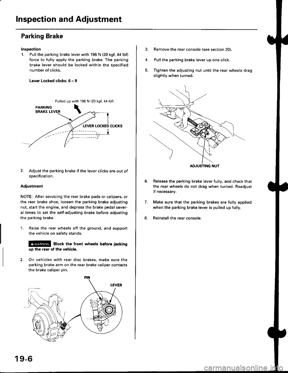
Inspection
1. Pull the parking brake lever with 196 N {20 kgf. 44 lbf)
force to fully apply the parking brake. The parking
brake lever should be locked within the sDecified
number of clicks.
Lever Locked clicks: 6 - I
Pulled up96 N 120 kgf,44lbf)
2. Adjust the parking brake if the lever clicks are out of
specification.
Adiusiment
NOTE: After servicing the rear brake pads or calipers, or
the rear brake shoe, loosen the parking brake adjusting
nut, start the engine, and depress the brake pedal sever-
al times to set the self-adjusting brake before adjusting
the parking brake.
1. Raise the rear wheels off the ground, and support
the vehicle on safety stands.
l@ Elock the front wheels bofore iackinguD the rear ot the v6hicle.
2. On vehicles with rear disc brakes, make sure theparking brake arm on the rear brake caliper contacts
the brake calioer Din.
with 1
\
19-6
Remove the rear console (see section 20).
Pullthe parking brake lever up one click,
Tighten the adjusting nut until the rear wheels drag
slightly when turned.
Belease the parking brake lever fully, and check that
the rear wheels do not drag when turned. Readjust
if necessarv.
Make sure that the parking brakes are fully applied
when the parking brake lever is pulled up fully.
Reinstall the rear console.
7.
8.
ADJUSTING NUT
Page 1161 of 2189
I
Bleeding
CAUTION:
. Always use Genuine Honda DOT 3 Brake Fluid. Using 8
non-Honda brak€ fluid can cause corrosion and
docrea3e the life of the system.
. Make surs ||o dirt or other foteign matter is allowed
to contaminate the brake fluid,
. Do not spill brake lluid on the vehicle, it may damago
the paint; if brake lluid doos contac{ the paint, wash
it ofl imm€diately with water.
NOTE: The reservoir on the master cylinder must be at
the MAX (upper) level mark at the start of the bleeding
procedure and checked after bleeding each brake
caliper. Add fluid as required.
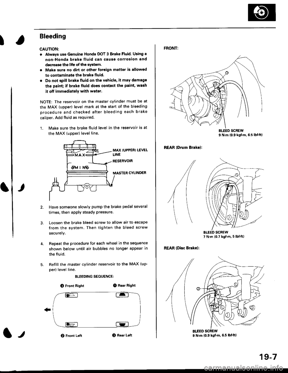
1. Make sure the brake fluid level in the reservoir is at
the MAX lupper) level line.
MAX {UPPER) LEVEL
CYLINDER
Have someone slowly pump the brake pedsl several
times, then apply steady Pressure.
Loosen the brake bleed screw to allow air to escape
from the system. Then tighten the bleed screw
securely.
Repeat the procedure for each wheel in the sequence
shown below until air bubbles no longer appear in
the fluid.
Refill the master cylinder reservoir to the MAX (up-
per) level line.
ELEEDING SEOUENCE:
O Front Right(D Bo.r Right
O Front LeftO Rear Left1,,
19-7
FRONTT
REAR lDrum Brakel:
REAR (Disc Brake):
AIEED SCREW9 N.m (0.9 ksf m, 6.5 lbf'ft)
Page 1175 of 2189
Master Cylinder/Brake Booster
IRemovaUlnstallation
CAUTION:
. Be care{ul nol to bend or damage the brake lines when
rsmoving the mastsr cYlinder.
. Do not soill brakefluid on the vehicle; it may damage
the paint; if brake fluid does contact the paint, wssh
it off immediatelY with water'
. To prevent spill3, cover the hose ioints with rags or
shop towels.
9. Remove the four booster mountlng nuts
10. Pull the brake booster forward until the clevis is
clear of the bulkhead.
11. Remove the brake booster from the engine com-
panmenr.'12. Install the brake booster and master cylinder in the
reverse order of removal.
CAUTION:
. When connecting the brake lines. make sure
that there is no inte erence between the brake
lines and oth6r Parts.
r Be careful not to bend or damage the brake lines
when installing the master cylinder.
NOTE: lf replacing the master cylinder or brake
booster, check and adiust the pushrod clearance
be{ore installing the master cylinder (see page 19-221'
Fill the master cylinder reservoir, and bleed the
brake svstem (see Page 19-7).
After installation. check the brake pedal height and
brake pedal tree play (see page l9-5) and adjust if
necessary.
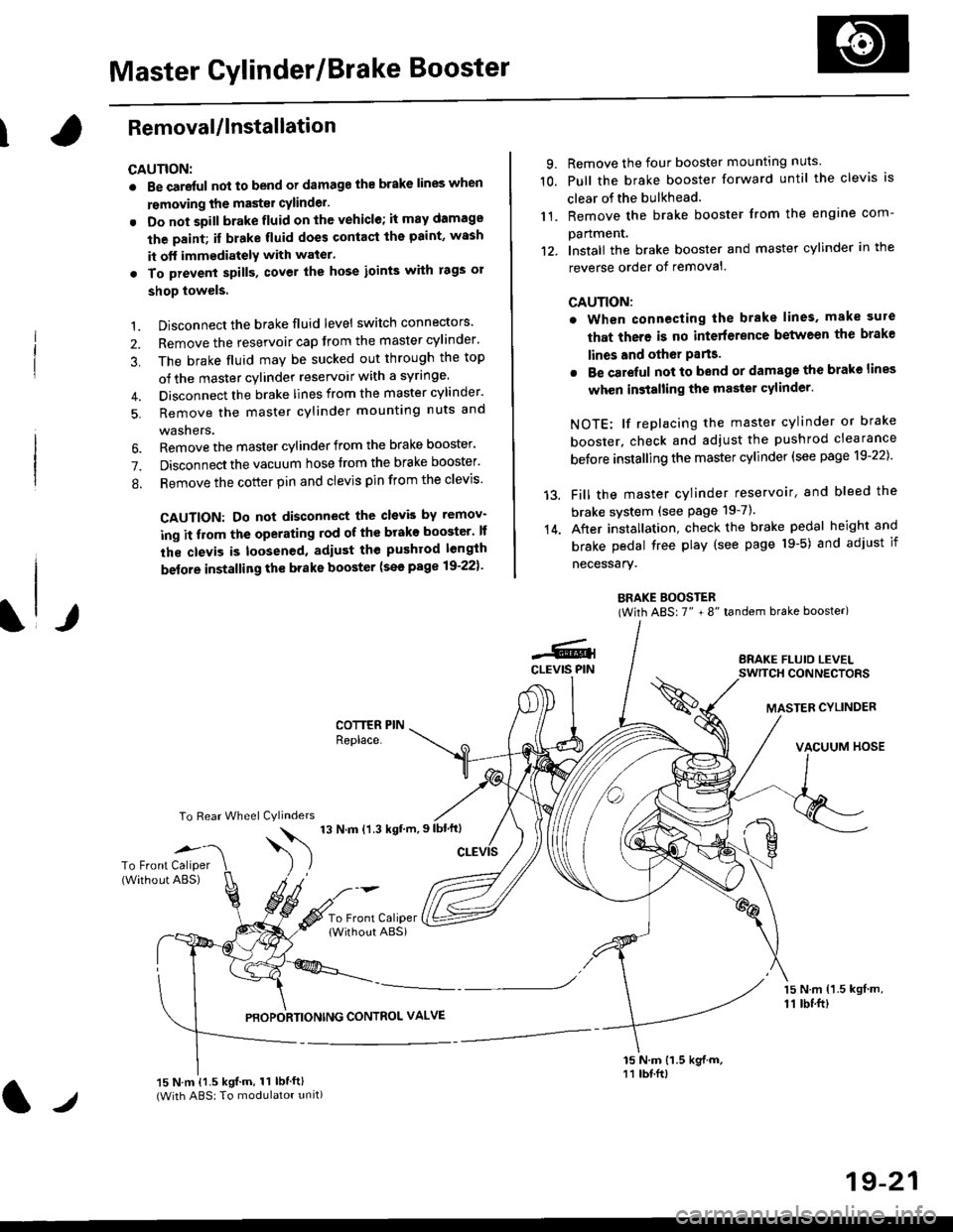
BRAKE BOOSTER(With ABS: 7" + 8" tandem brake booster)
BRAKE FLUIO LEVELSWITCH CONNECTORS
MASTER CYLINDER
VACUUM HOSE
1.
2.
3,
5.
Disconnect the brake fluid level switch connectors'
Remove the reservoir cap from the master cylinder'
The brake fluid may be sucked out through the top
of the master cylinder reservoir with a syrlnge.
Disconnect the brake lines from the master cylinder'
Remove the master cylinder mounting nuts and
washers.
\l/
6. Remove the master cylinder from the brake booster'
7. Disconnect the vacuum hose trom the brake booster'
8. Remove the cotter pin and clevis pin from the clevis'
CAUTION: Do not disconnect the clevb by remov-
ing it from the operating rod of the brako booster' lf
the clevis is loosened, adiust the pushrod length
before installing th€ brake booster (see page 19-221'
COTTER PINReplace.
To Rear Wheel Cylinders
14.
-6.4CLEVIS PIN
To Front Caliper(Without ABS)$
t'N't'ttrnt'-''
To Front CaliperlWithout ABSi
PBOPORTIONING CONTROL VALVE
15 N.m {1.5 kgl m,11 tbtft)
15 N.m {1.5 kgif.m, 11 lbtft}(With ABS: To modulator unit)lr
19-21
Page 1178 of 2189
Rear Brake Pads
Inspection and Replacement
Never use an air hose or dry brush to clean brakeassemblies.
Use an OsHA-apptoved vacuum cl€aner to avoidbreathing brake dust,
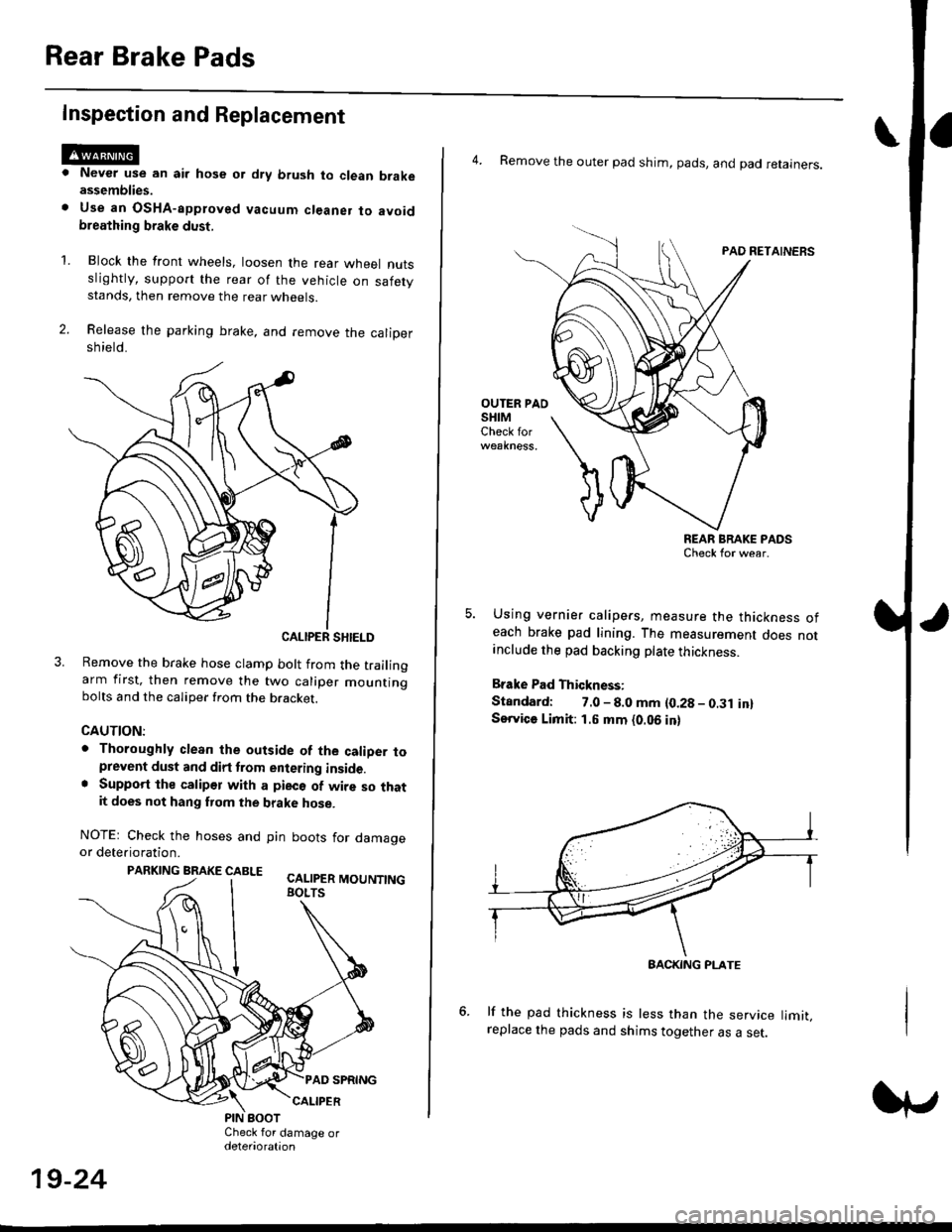
Block the front wheels, loosen the rear wneet nutsslightly, support the rear of the vehicle on safetystands, then remove the rear wheels.
Release the parking brake, and remove the calioersh ield.
CALIPER SHIELD
Remove the brake hose clamp bolt from the trailingarm first, then remove the two caliper mountingbolts and the caliper from the bracket.
CAUTION:
. Thoroughly clean the outside of the caliDer toprevent dust and dirt trom entering inside.. Support the calipor with a pieco of wire so thatit does not hang fuom the brake hose.
NOTEr Check the hoses and pin boots for damageor deterioration.
PARKING BRAKE CABLE ^.. ._-_ ---.
'L
19-24
4. Remove the outer pad shim, pads, and pad retainers.
PAO RETAINERS
OUTER PAOSHIMCheck for
REAR BRAKE PADSCheck for wear.
Using vernier calipers, measure the thickness ofeach brake pad lining. The measurement does notanclude the pad backing plate thickness.
Brake Pad Thickness:
Standard: 7.0 - 8.0 mm {0.28 - 0.31 in}Service Limit: 1.5 mm {0.06 in}
lf the pad thickness is less than the service limit,replace the pads and shims together as a set.
BACKING PI-ATE
Page 1180 of 2189
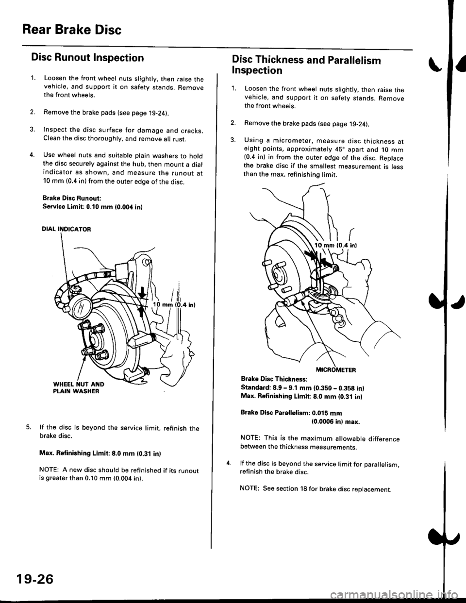
Rear Brake Disc
Disc Runout Inspection
1.Loosen the front wheel nuts slightly, then raise thevehicle, and suppon it on safety stands. Removethe front wheels.
Remove the brake pads (see page 19-24).
Inspect the disc surface for damage and cracks.Clean the disc thoaoughly, and remove a
rust.
Use wheel nuts and suitable plain washers to holdthe disc securely against the hub. then mount a dialindicator as shown. and measure the runout at10 mm (0.4 in) from the outer edge of the disc.
Brake Disc Runout:
Service Limit:0.10 mm {0.00,t in)
5. lf the disc is beyond the service limit, refinish thebrake disc,
Max. Retinishing Limit: 8.0 mm {0.31 in)
NOTE: A new disc should be refinished if its runoutis greater than 0.10 mm (0.004 in).
19-26
Disc Thickness and Parallelism
Inspection
1. Loosen the front wheel nuts slightly, then raise thevehicle, and support it on safety stands. Removethe front wh6els.
2. Remove the brake pads (see page j9-24).
3. Using a micrometer. measure disc thickness aterght points, approximately 45" apart and 1o mm{0.4 in) in from the outer edge of the disc. Replacethe brake disc if the smallest measurement is lessthan the max. refinishing limit.
Brake Disc Thickness:
Standard: 8.9 - 9.1 mm (0.350 - 0.358 in)Max. Rsfinishing Limit: 8.0 mm {0.31 in}
Brake Disc Parallelirm: 0.015 mm(0.0006 inl msx.
NOTE; This is the maximum allowable differencebetween the thickness measurements.
4. lf the disc is beyond the service limit for Darallelism.refinish the brake disc.
NOTE; See section 18 for brake disc replacement.
Page 1181 of 2189
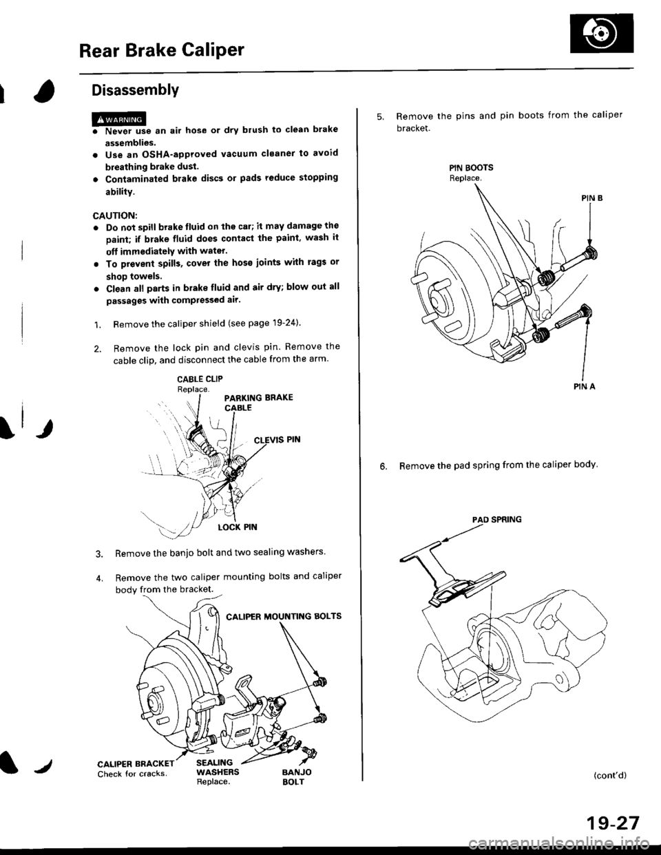
Rear Brake Caliper
Disassembly
@f l',lever use an air hose or dry brush to clean
assemblies.
. Use an OsHA-approved vacuum cleaner to
brake
avoid
breathing brake dust.
. Contaminated brake discs or pads reduce stopping
ability.
CAUTION:
. Do not spill brake tluid on the cal; h may damage the
paint; if brake fluid does contact the paint, wash ii
ofl immediatelY with water.
. To prevent spills, cover the hose ioints whh rags or
shop tow€ls.
. Clean all parts in brake fluid and air dry; blow out all
passagss with complessed air.
1. Remove the caliper shield (see page 19-24).
2. Remove the lock pin and clevis pin. Remove the
cable clip, and disconnect the cable from the arm
CABLE CLIP
Remove the banjo bolt and two sealing washers
Remove the two caliper mounting bolts and caliper
body from the bracket.
CALIPER MOUNTNG AOLTS
CALIPER BRACKETCheck for cracksSEALINGWASHERSReplace.BANJOBOLT
5, Remove the pins and pin boots from the caliper
bracket.
6. Remove the pad spring from the caliper body
PIN A
(cont'd)
19-27
Page 1182 of 2189
Rear Brake Galiper
Disassembly (cont'd)
7. Remove the piston by rotating the piston counter-clockwise with the tool, and remove the piston
boot.
CAUTION: Avoid damaging the piston.
PISTON BOOTReplace.
Remove the piston seal.
CAUTION: Take care not to damage the cylinderbore.
CALIPER BODYCheck for scoring on
9. Install the special tool between the caliper bodv andspnng cover.
CAUTION: Be caretul not to damags the inside ofthe caliper cylinder during caliper disassembty.
BRAKE SPRINGCOMPRESSOR07HAE - SG00100
11.
LOCKNUTS
Position the locknuts as shown. then turn the shaftuntil the plate just contacts the caliper body.
NOTE: Do not compress the spring under thespring cover.
Turn the shaft clockwise 1/4 -'ll2 tu.n to comoressadjusting spring B in the caliper body.
CAUTION: To preyant damage to the inner compo-nonts. do not turn the shaft mor€ than 1/2 turn.
SHAFT
LOCKNUTS
PISTON SEALReplace.
ADJUSTII{GSPRING 8
19-28