Page 809 of 2189

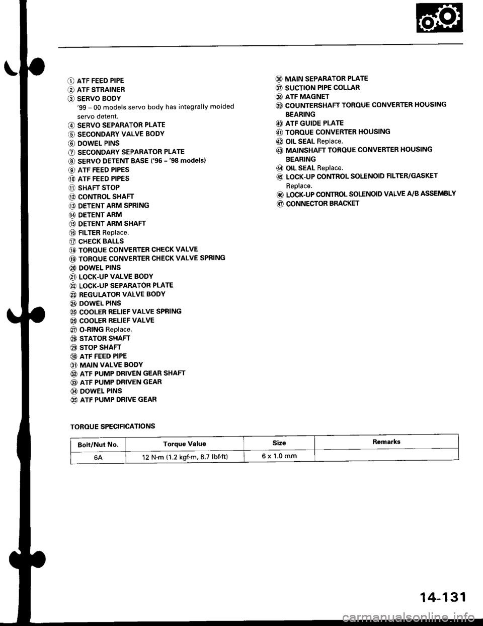
O ATF FEED PIPE
O ATF STRAINER
O SERVO BODY'99 - 00 models servo body has integrally molded
servo detent.
@ SERVO SEPARATOR PLATE
(' SECONDARY VALVE BODY
@ DOWEL P|NS
O SECONDARY SEPARATOR PLATE
@ SERVO DETENT BASE ('�96 -'98 models)
O ATF FEED PIPES
(D ATF FEED PIPES
O SHAFT STOP
@ CONTROL SHAFT
€D DETENT ARM SPRING
@ DETENT ARM
(9 DETENT ARM SHAFT
@ FILTER Replace.
(? CHECK BALLS
@ TOROUE CONVERTER CHECK VALVE
@ TOROUE CONVERTER CHECK VALVE SPRING
@ DOWEL PINS
@ LOCK.UP VALVE BODY
@ LOCK-UP SEPARATOR PLATE
@ REGULATOR VALVE BODY
@} DOWEL PINS
@ COOLER RELIEF VALVE SPRING
@ COOLER RELIEF VALVE
@ O-RING Replace.
@ STATOR SHAFT
@ STOP SHAFT
@ ATF FEED PIPE
@ MAIN VALVE BODY
@ ATF PUMP DRIVEN GEAR SHAFT
@ ATF PUMP DRIVEN GEAR
@ DOWEL PINS
65) ATF PUMP DRIVE GEAR
@ MAIN SEPARATOR PLATE
@ SUCTION PIPE COLLAR
@ ATF MAGNET
@ COUNTERSHAFT TOROUE CONVERTER HOUSING
BEARING
@ ATF GUIDE PLATE
@ ToRoUE CONVERTER HOUSING
@ OIL SEAL Replace.
@ MAINSHAFT TOROUE CONVERTER HOUSING
BEARING
@) olL SEAL Replace.
@ LOCK-UP CONTROL SOLENOID FILTER/GASKET
Reolace.
@ LOCK-UP CONIROL SOLENOID VALVE A/B ASSEMELY
@ CONNECTOR BRACKET
TOROUE SPECIFICANONS
Bolt/Nut No.Torque ValugSiz€Remarkg
12 N.m (1.2 kgf.m,8.7 lbnft)6x1,0mm
14-131
Page 810 of 2189
End Cover
Removal
NOTE:
. Cleanall parts thoroughly in solvent or carburetor cleaner, and drywith compressed air,. Blow out all passages,
. When removing the right side cover, replace the following:- O-rings- Mainshaft and countershaft locknuts- Conical spring washgrs- End cover gasket
- Lock washer- Sealing washers
END COVER6 x 1.0 mm BOLT13 Bolts
PARK PAWL
PARK ITVER
LOCK WASHER
COUI{TERSI{AFTLINE AOLT
tST GEAF COLLAR
I
14-132
SEALING WASHERS
Page 826 of 2189

Mainshaft
Disassembly/lnspestion/Reassembly
NOTE:
. Lubricate all parts with ATF during reassembly..Inspectthethrustneedlebearingsandtheneedlebearingsforgallingandroughmovement,
. Before installing the O-rings, wrap the shaft splines with tape to prevent damaging the O_rings.. Locknut has left-hand threads.
LOCKNUT {FLANGE NUTI21 x 1.25 mm78 N.m (8.0 kgl.m,58 lbt.fttReplace.Left-hand threadsSNAP RINGCONICAL SPRING WASHERReolace.
lST CLUTCHASSEMBLYTHRUST WASHER
THRUST NEEOI.EBEARING
4TH GEAN
O-RINGSReplace.
THRUST WASHER
THRUST NEEDLEBEARING
MAINSHAFTCheck splines for excessivewear and oamage.Check bearing surtace for scoring,scratches and excessive wear.
BEARINGBEARINGS
THRUST NEEDLEBEABING
4TH GEAR COLLAR
2ND/4TH CLUTCHASSEMBLY
THRUST NEEDLEEEARING
2NO GEAB
NEEDLE BEABING
THRUST NEEDLEBEARING
1ST GEAR
1ST GEARCOLLAR
TRANSMISSIONHOUSING BEARING
O-RINGSReplace.
THRUST WASHER, 36.5 x 55 mmSelective part.
SEALING RINGS,35 mm
Install the sealing ringmating faces as shown,
RING,29 mm
NEEDLE BEARING
SET RING
14-148
Page 850 of 2189
Torque Converter Housing Bearings
Mainshaft Bearing/Oil Seal Replacement
1.Remove the mainshaft bearing and oil seal using
the special tools as shown.
3/8"16 SLIOE HAMMER
ADJUSTAELE BEARINGPULLER, 25 - ilo mm07736 - A01000a
L
14-172
2. Drive in the new mainshaft bearing until it bottomsin the housing using the special tools as shown.
DRIVER077€ - 0010000
lnstall the new oil seal flush with the housing using
the special tools as shown.
DBIVER07749 - 0o l0(xt0
ATTACHMENT,72x75 mfi07746 - 001 0600
Page 854 of 2189
Transmission
Reasembly
NOTE;
. Coat all parts with ATF.. Beplace the following parts:- O-rings- Lock washers- Gaskets- Mainshaft and countershaft locknuts and conical spring washers- Sealing washers
TOROUE: l2 N.m (1.2 ksf'm,8.7 lbf.ft)
6 x 'l.0 mm7 BoltsFEED PIPE: A
LOCK.UP VALVEBODY
LOCK.UP SEPARATORPLATE
REGULATOR VALVEBODY
DOWEL PINS. 2
6xl.0mm1 BoltATF STRAINERATF FEEDPIPES:
a
COOIER RELIEF VALVE
TOROUE CONVENIERCHECK VALVESTATOR SHAFT
O.RING
STOP SHAFT
ATF FEEO PIPE: H
5x1.0mm5 Bolts
DOWEL PINS.
MAIN VALVE BODY
ATF PUMP
SERVO SEPARATORPLAYE
6x1.0mm7 Bolts
SERVO BODY
SECONOARYSEPARATOR PLATE
CONTROL
GEAR SHAFT
ATF PUMP DFIVENGEAR
MAIN SEPARATORPLATE
DOWEL PINS,
/ SHAFI
' -
7r(
t'se - oo ^od"t"t
lli
triTOROUE CONVERTERHOUSING
NOTE: The illustration shows the'96 - 98 modsls, the'99 - 00 models do not have the servo detent base; the servodetent is integralwith the servo bodv.
14-176
L-
Page 859 of 2189
36. Remove the special tool from mainshaft, then stake
each locknut using a 3.5 mm punch as shown'
COUNTERSHAFTLOCKNUT
Set the park lever in the El position, then verify that
the park Pawl engages the Park gear
lf the Dawl does not engage fully, check the park
pawl stop clearance (see page 14-175).
Tighten the lock boll and bend the lock tab'
10 tbl.ftl
a'f
38.
ao
LOCKWASHEF
0.7 - 1.2 mm(0.03 - 0.05 in)
Erl.Omm14 t{.m (1.4 kgf'm,
\.- (o)
40. Instsllthe end cover with two dowel pinsandanew
gasket (thirteen bolts)'
TOROUE: 12 N'm (1.2 tgf'm. 8.7 lbf'ft}
END COVER
lnstall the ATF cooler lines with new sealing wash-
9rs.
TOROUE: 28 N.m {2.9 kgf'm. 21 lbt'ft1
Install the ATF diPstick.
41.
14-181
Page 1066 of 2189

Steering Gearbox
Reassembly (cont'dl
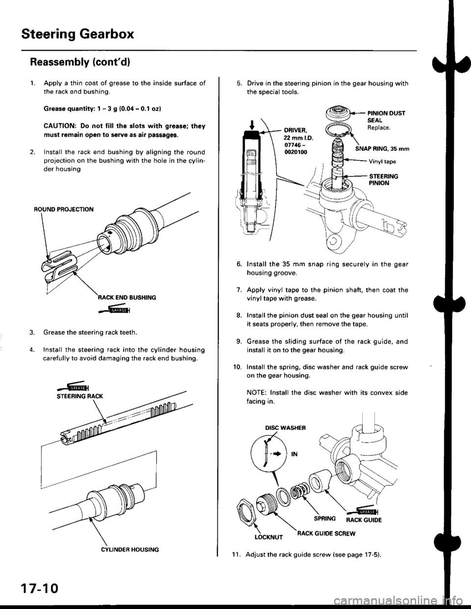
LApply a thin coat of grease to the inside surface of
the rack end bushing.
Grease quantity: 1 - 3 S 10.04-0.1 ozl
CAUTION: Do not till the slots with greas€; th€y
must remain open to serve as air passages,
Install the rack end bushing by aligning the round
projection on the bushing with the hole in the cylin-
der housing
4.
Grease the steering rack teeth.
Install the steering rack into the cylinder housing
carefully to avoid damaging the rack end bushing.
CYLINDER HOUSING
17-10
11. Adjust the rack guide screw (see page 17-5).
Drive in the steering pinion in the gear housing with
the soecial tools.
ORIVER.22 mm l.D.o7716-qr20100SNAP RING, 35 mm
PINION DUSTSEALReplace.
Vinyltape
STEERINGPINION
7.
Install the 35 mm snap ring securely in the gear
housing groove.
Apply vinyl tape to the pinion shaft, then coat the
vinyltape with grease.
Install the pinion dust seal on the gear housing until
it seats properly, then remove the tape.
Grease the sliding surface of the rack guide, and
install it on to the gear housing.
Install the spring, disc washer and rack guide screw
on the gear housing.
NOTE: Install the disc washer with its convex side
facing in.
LOCKNUT
SPRING RACK GUTDE
RACK GUIOE SCREW
10.
Dtsc w,
a(-\
l1 *l
\, ,/
\
Page 1107 of 2189

t
t5.
16.
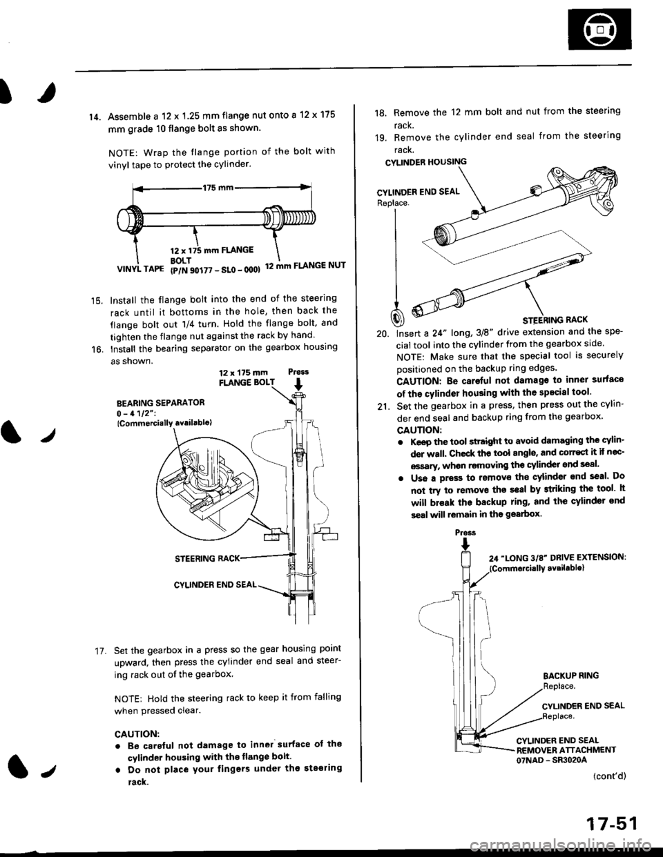
14. Assemble a 12 x 1.25 mm flange nut onto a 12 x 175
mm grade 10 flange bolt as shown.
NOTE: Wrap the tlange portion of the bolt with
vinyl tape to protect the cylinder.
12,mm FLANGE
BOLT12 mm FLANGE NUTVINYL TAPG {p/N 90i77 - SLo - 000}
Install the flange bolt into the end of the steering
rack until it bottoms in the hole, then back the
flange bolt out 'll4 turn. Hold the flange bolt, and
tighten the flange nut against the rack by hand.
Install the bearing separator on the gearbox housing
a5 snown.
FLANGE BOLT
BEARING SEPARATOR0 - 1112" I
lCommercially availablo)
STEERING RACK
CYLINDER END SEAL
Set the gearbox in a press so the gear housing point
upward, then press the cylinder end seal and steer-
ing rack out of the gearbox
NOTE: Hold the steering rack to keep it from falling
when pressed clear.
CAUTION:
. Be carsful not damage to inn6l surface ot the
cylinder housing with the flange bolt.
. Do not place your lingers under th€ ste€ring
rack.
t./
17.
12 x 175 mm Ptess
1.,
the spe-
srcle.
securely
Replace. J__--'- ,----)t'| ,-----'" ,-,-'-'| fiN ----'
| .Wl'----
I
t
-'4a
| ^--.'--4
A ooY----- \
Q) * srerhtnc nact
20. lnsert a 24" long,3E" drive extension and
cial tool into the cylinder from the gearbox
NOTE: Make sure that the special tool is
positioned on the backup ring edges'
18, Remove the 12 mm bolt and nut from the steering
rack,
19. Remove the cylinder end seal from the steering
racK.
CYLINDER HOUSING
CAUTION: Be caroful not damago to inner surfaco
of the cylinder housing with the specisl tool'
21. Set the gearbox in a press, then press out the cYlin-
der end seal and backup ring from the gearbox,
GAUTION:
. Keep the tool sttaight to avoid damaging the cylin'
der wall. Check th€ tool angls, and corr€st it if nec-
€ssary, whon rsmoving the cylinder snd seal.
. Uss a pross to removs tho cylinder end seal. Do
not try to removo ths seal by striking the tool h
will br€ak the backup ring. and the cylinder snd
s€al will lemain in tho gearbox.
BACKUP RING
CYLINDER END SEAL
CYLINDER END SEALREMOVER ATTACHMENT07NAD - SR3020A
(cont'd)
17-51
Pross