Page 1733 of 2189

)
l-l
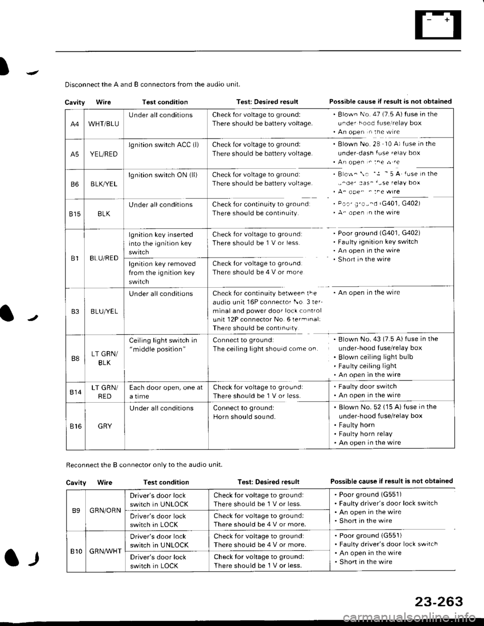
Disconnect the A and B connectors from the audio unit.
Cavity WireTest conditionTest: Desired resultPossible cause if result is not obtained
Reconnect the B connector only to the audio unit.
Cavity WireTest conditionTest: Desired resultPossible cause iI result is not obtained
B9GRN/ORN
Driver's door lock
switch in UNLOCK
Check for voltage to ground:
There should be 1 V or less.
. Poor ground 1G551). Faulty driver's door lock switch. An open in the wire. Short in the wireDriver's door lock
switch in LOCK
Check for voltage to grou nd:
There should be 4 V or more.
810G R NAr'r'HT
Driver's door lock
switch in UNLOCK
Check for voltage to ground:
There should be 4 V or more.
. Poor ground (G551)
. Faulty driver's door lock switch. An open in the wire. Shon in the wireDriver's door lock
switch in LOCK
Check lor voltage to ground:
There should be I V or less.
23-263
A4WHT/BLU
LJnder all conditionsCheck {or voltage to ground:
There should be battery voltage.
. Blown No. 47 (7.5 A) tuse in the
under hood fuse,i relay box. An open n the w re
A5YEL/RED
lg nition swirch ACC (l)Check for voltage to ground:
There should be battery voltage.
Blown No. 28 , I0 A) f use in the
under dash fuse.elay box
An open " :ne n re
Check for voltage to ground:
There should be battery voltage.
Check for continuity to groundr
There should be continuity.
B o$. \. '.1 - 5 A' iuse n the
,,^oe' aas_'-se relay box
A_ ooe^ ' :ne wrre
Pc.' E'o--d rG401, G402)
A- ooen n lhe wire
B6B LK,/YE L
lgnition switch ON0l)
8158LK
Under all conditions
B1BLU/RED
lgnition key inserted
into the ignition key
swrtch
Check for voltage to ground:
There should be 1 V or less
Check for voltage to ground:
There should be 4 V or more
Poor ground (G401, G402)
Faulty ignition key switch
An open in the wire
Short in the wire
An open in the wireCheck for continuity berwee. lFe
audio unit 16P connector l-o 3ler-
minal and power door lock control
unit 12P connector No. 6 lermrnal:
There should be continu ty
lgnition key removed
from the ig nition key
swtlcn
B3B LUlt/E L
U nderall conditions
B8LT GRN/
BLK
Ceiling light switch in"middle position"
Connect to ground:
The ceiling lighr shouldcome on.
Blown No.43 (7.5 A) fuse in the
under-hood Iuse/relay box
Blown ceiling light bulb
Fau lty ceiling light
An open in the wire
814LT GRN/
RED
Each door open, one at
a time
Check tor voltage to ground:
There should be'l V or less.
. Faulty door switch. An open in the wire
Br6GRY
U nderall conditionsConnect to groundl
Horn should sound.
. Blown No. 52 ('15 A) fuse in the
under-hood fuse/relay box
. Fau lty horn. Faulty horn relay. An open in the wire
Page 1741 of 2189
Component/Wiring Locations
)
Index: With Front Passenger's Airbag
SRS INDICATOR LIGHT (ln the gauge assemblvl
Troubleshooting, Page 24 13
Gauge assembly, section 23CABLE REEL
Replacemenlpage 2!-t 2
To HORN SWITCH
SRS UNIT(lncluding safing sensor
and imPact sensorl
Replacement Page 24 76
To DRIVER'S AIRBAG
DASHBOARD WIRE HARNESS
to SRS INDICATOB LIGHT in
GAUGE ASSEMBLY5P CONNECTOB
DBIVER'S AIRBAG
Beplacement,page 24-61Disposal, page 24 70FRONT PASSENGER'S AIBBAG
Replacement, Page 24_67
Disposal, Page 24 70
t
SRS MAIN HARNESSto CABI-E RE€L2P CONNECTOR
SRS MAIN
SERVICE CHECKCONNECTOR {2PI
IBRN, BLK]
to UNOER-OASHFUSE/RELAY BOX2P CONNECTOR
SRS MAIN HARNESSto FRONT PASSENGER'SAIRBAG2P CONNECTOB
SRS MAIN HARNESSto SRS UNITr8P CONNECTOR
SBS MAIN HARNESSto MAINWIRE HARNESS3P CONNECTOR
MEMORY ERASE SIGNAL(MES) CONNECTOR I2P)
[GRY, GRYI or IGRN. GRNI
MAIN WIRE HARNESSto DASHBOARD WIRE HARNESS
24P CONNECTOR
2+3
t,
Page 1742 of 2189
Gomponent/Wiring Locations
Index: Without Front Passenger's Airbag (some Canada Modelsl
SRS INDICATOR LIGHT (ln the gauge assembly)Troubleshooting, page 24-13Gauge assembly, section 23
DRIVER'S AIRSAGReplacement,page 24-67Disposal, page 24-70
SRS UNITGROUNO
To HORN SWITCH
SRS MAIN HARNESS
SRS UNIT{lncluding safing sensorand impact sensor)Replacement. page 24,76
To CRUISE CONTROLSET/RESUME SWITCH
oo/ \oo
To DRIVER,S AIRBAG
DASHBOARD WIRE HARNESSto SRS INDICATOR LIGHT inGAUGE ASSEMBLY5P CONNECTOR
SERVICE CHECKCONNECTOR {2P}IB8N, BLKI
SRS MAINto UNDER-DASHFUSE/RELAY BOX2P CONNECTOR
SRS MAIN HARNESSto SRS UNIT18P CONNECTOR
SRS MAIN HARNESSto MAINWIREHARNESS3P CONNECTOR
MEMORY ERASE SIGNAL(MES) CONNECTON (2P'
IGRY, GRYI o. IGRN, GRNI
MAIN WIRE HARNESSto DASHBOARD WIRE HARNESS24P CONNECTOR
24-4
DUMMY RESISTOB
Page 1785 of 2189

)
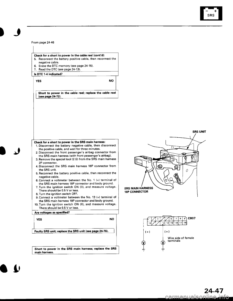
From page 24-46
Chock for a short to power in the cabls roel lcont'dl:5. Reconnect the battery positive cable, then reconnect thenegative cable.6. Erase the DTC memory lsee page 24-15).7. Read the DTC (see pa1e24-131.
b DTC 1-4 indicat€d?
YESNO
Short to power in tho cable reel; roplac. tho cable reel
lsee Dase 24-721.
Chock for e short to powot in the SRS main hornoas:
1. Disconnect the battery nogative cable, then disconnect
the positive cable, and wait for three minutes.2- Disconnect the front passenger's airbag connector lrom
the SRS main harness (with front passenger's airbag).
3. Remove the special tool (2 0) trom the SRS main harn€ss
2P connector./t. Disconnect the SRS main harness 18P connector from
the sRs unit.5. Reconn6ct the battery positive cable, then reconnect the
negative cable.6. Connect a voltmeter between the No. 1 {+i terminal of
the SRS main harness 18P connector and body ground.
7. Turn the ignilion switch ON lll), and measure voltageThere should be 0.5 V or less.8. Turn the ignition switch OFF.9. Connect a voltmeter between the No. 13 (+) torminal ol
the SRS main harness 18P connector 8nd body ground.
lO.Turn the ignition switch ON (ll), and measure voltage
There should be 0.5 V or less.
Aro voltrges a3 specified?
YESNO
Fauftv SRS unh; roplacc tho SRS unh {soe pago 2+761'
Short to power in the SRS main h.rness; .eplace rhe SRS
main harness.
SRS UNIT
IJ
a0
24-47
Page 1807 of 2189
)
5, Reconnect the airbag connector(s)'
Front Passengor's Side:
a Attach the airbag connector to the connector holder'
then reinstallthe glove box.
FRONT PASSENGER'S AIRBAG
oo
24-69
Driver's Side:
a Connect the driver's airbag 2P connector to the cable
reel 2P connector, then install the acc€ss panel on the
steering wheel
DRIVER'S AIRBAG2P CONNECTOR
6. Connect the battery positive cable, then connect the
negative cable.
7. After installing the
operatlon:
. Turn the ignition
tor light should
and then go off
a Make sure both horn buttons work
airbag, confirm Proper sYstem
switch ON (ll); the SRS indica-
come on for about six seconds
Page 1810 of 2189

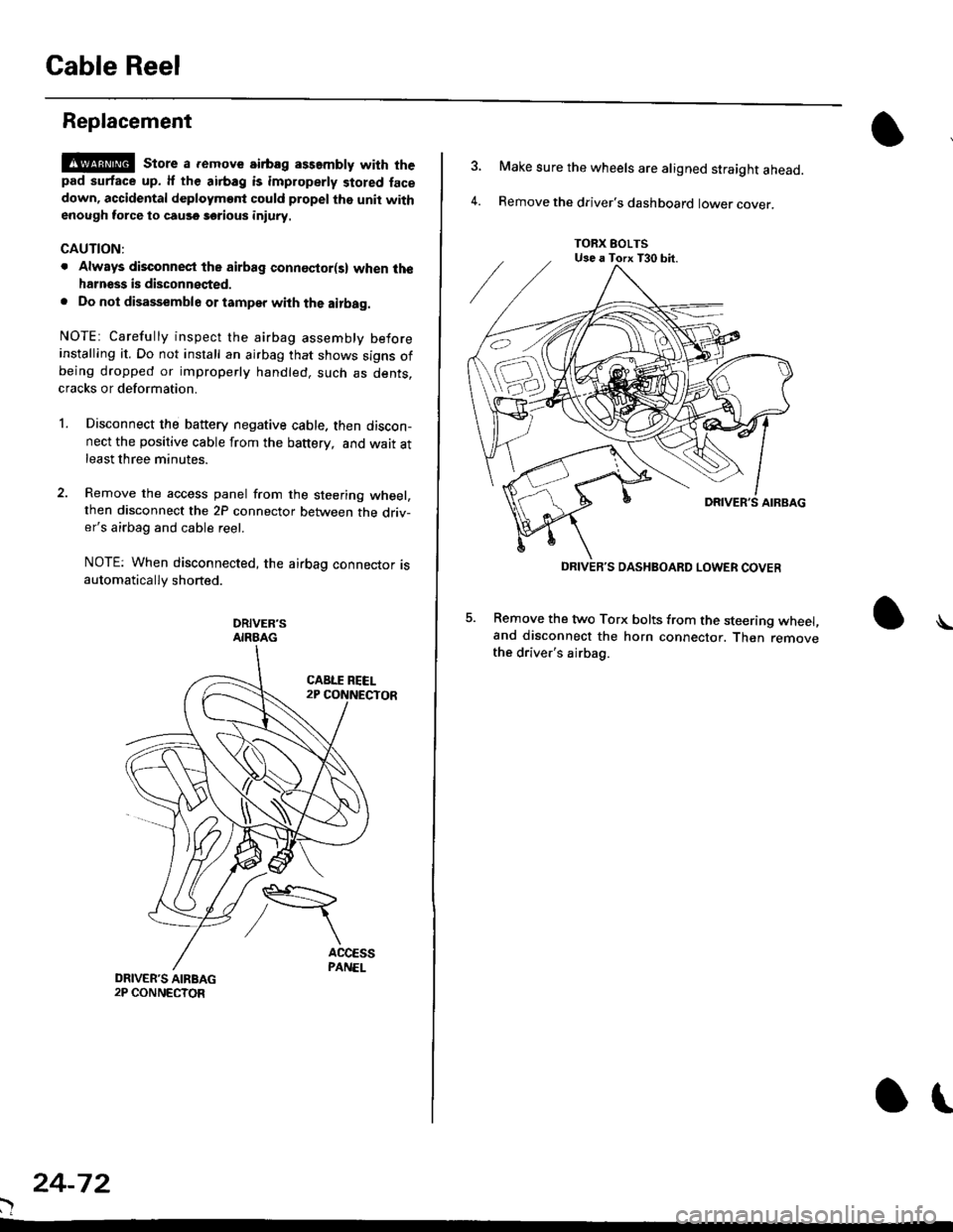
Gable Reel
Replacement
!@@ store a .emove airbag assambly with thepad surtace up. lf the airbag is improperly stored face
down, accidental deploymont could propel the unit withenough force to cause sorious iniury.
CAUTION:
. Alwsys disconnect the airbag connoctor(s) when ih€harness is disconngcted.
. Do not disassemble or tamper with the airbag.
NOTE: Carefully inspect the airbag assembly beforeinstalling it. Do not install an airbag that shows signs ofbeing dropped or improperly handled. such as dents,cracks or deformation.
l.Disconnect the battery negative cable. then discon-nect the positive cable from the battery, and wait atleast three minutes.
Remove the access panel from the steering wheel,then disconnect the 2P connector between the driv-er's airbag and cable reel.
NOTE: When disconnected, the airbag connector isautomatically shorted.
DRIVER'SAIRBAG
)
24-72
or
TORX EOLTSUse a Torx T30 bit.
DRIVEB'S DASHBOARD LOWER COVER
4.
Make sure the wheels are aligned straight ahead.
Remove the driver's dashboard lower cover.
5. Remove the two Torx bolts from the steering wheel,and disconnect the horn connector. Then removethe driver's airbag.
\
Page 1811 of 2189
\
6. Disconnect the connectors from the horn and cruise
control sevresume switches, then remove the steer-
ing wheel nut.
STEERINGNUT
CRUISE CONTROLSET/RESUMESWITCH CONNECTOR
)
HORN CONNECTOR
Remove the steerlng
pulrer.
CABLE REEL2P CONNECYOR
wheel using a steering wheel7.
STEERING WHEEL PULLEF
{Commerciallv_available)
)U
8. Remove the column covers.
Disconnect the 3P connector between the main wire
harness and cable reel sub-harness, 8nd the 2P con-
nector between the cable reel and SRS main harness'
CONNECTORHOLOER
SRS MAIN HARNESS2P CONNECTON
CABLE REEL SUBHARNESS3P CONNECTOR
10. Remove the cable reel from the column {cont'd}
24,73
--/
CABLE REEL
Page 1812 of 2189

Cable Reel
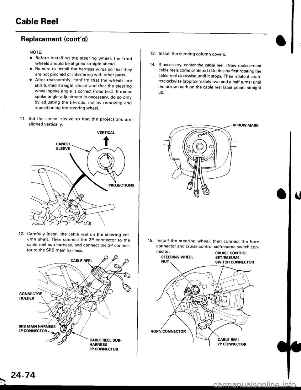
Replacement (cont'd)
11.
NOTE:
. Before installing the steering wheel, the front
wheels should be aligned straight ahead.. Be sure to install the harness wires so that theyare not pinched or interfering with other parts.. After reassembly. confirm that the wheels arestill turned straight ahead and that the steeringwheel spoke angle is correct (road test). lf minor
spoke angle adjustment is necessary, do so onlyby adjusting the tie-rods, not by removing andrepositioning the steering wheel.
Set the cancel sleeve so that the projections arealigned venically.
PROJECTIONS
12. Carefully install the cable reel on the steering column shaft. Then connect the 3p connector to thecable reel sub-harness, and connect the 2p connec-tor to the SRS main harness.
. 24-74
Install the steering column covers.
lf necessary, center the cable reel. {New replacementcable reels come centered.) Do this by first rotating thecable reel clockwise until it stops. Then rotate tt counterclockwise (approximately two and a half turns) untilthe arrow mark on the cable reel label points straightup.
ARROW MARK
15. lnstall the sleering wheel, then connect the hornconneclor and cruise control sevresume switch con
14.
neclor.
STEERING WHEELCRUISE CONTROLSET/RESUM€