Page 847 of 2189
OilSealRemoval
1. Remov€ the differential assembly.
2, Remove the oil seal from the transmission housing,
OIL SEALRoplace.
the oil seal from ths torque converterRemove
housing.
OIL SEALReplace.
TOROUE CONVERTEFHOUSING
Oil Seal Installation/Side Glearance
1. Install a 2.50 mm (0.098 in) set ring,80 mm in trans-
mission housing.
NOTE: Do not install the oil seal vet.
RING, 80 mm
TRAITISMISSlONHOUS|l{G
Install the differential assembly into the torque con-
verter housing using the specialtool as shown.
Install the transmission housing and tighten the
bolts {see page 14-178 and 14-179).
{cont'd)
14-169
Page 848 of 2189

Differential
Oil Seal Installation/Side Clearance (cont'd)
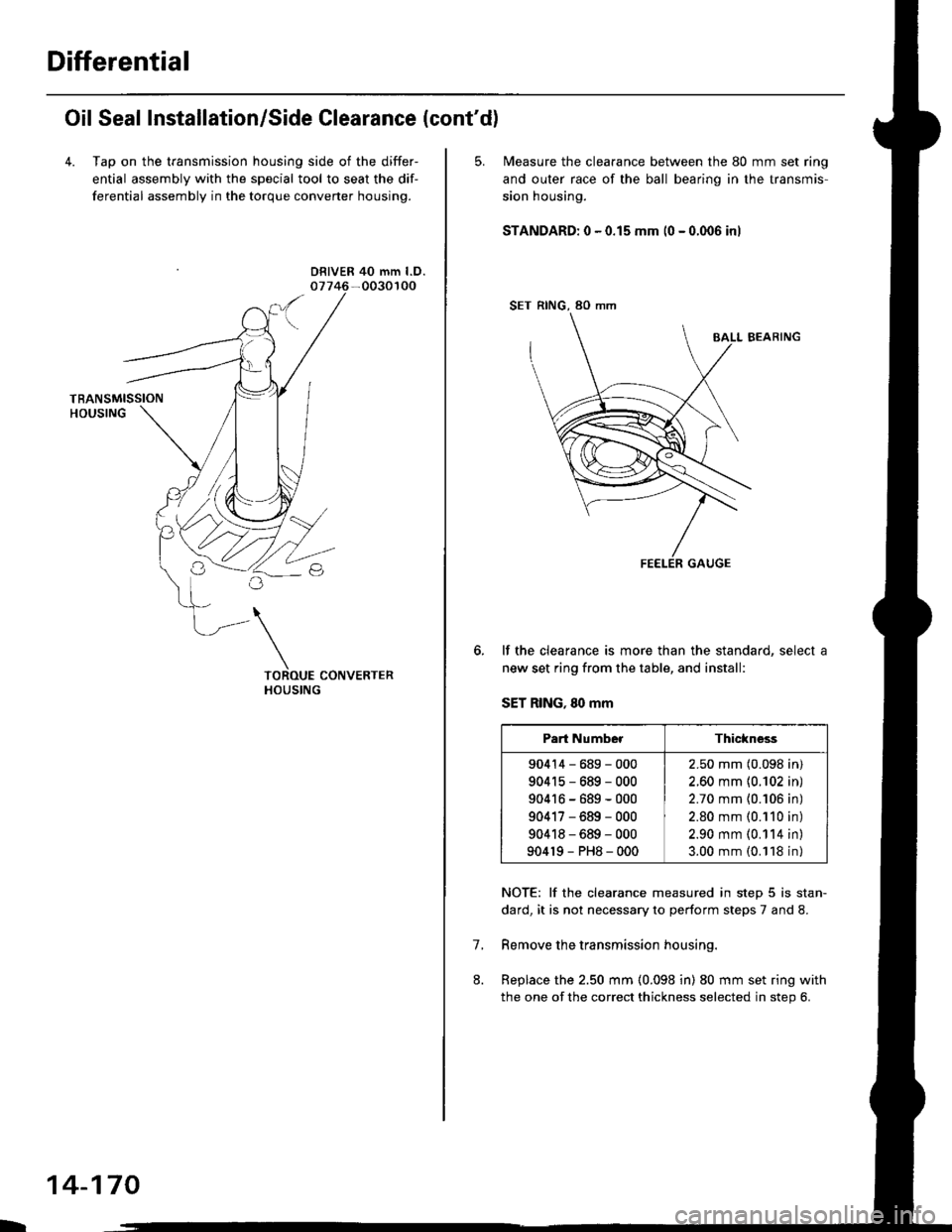
4. Tap on the transmission housing side of the differ-
ential assembly with the special tool to seat the dif-
ferential assembly in the torque converter housing.
DRIVER 40 mm l.D.
L
14-170
5. N4easure the clearance between the 80 mm set ring
and outer race of the ball bearino in the transmis-
sion housing.
STANDARD: 0 - 0.15 mm (0 - 0.006 inl
SET RING, 80 mm
BALL BEARING
lf the clearance is more than the standard, select a
new set ring from the table, and install:
SET RING, 80 mm
NOTE: lf the clearance measured in step 5 is stan-
dard, it is not necessary to perform steps 7 and 8.
Remove the transmission housing.
Replace the 2.50 mm (0.098 in) 80 mm set ring with
the one of the correct thickness selected in step 6.
7.
Part NumberThickness
90414-689-000
904r5-689-000
90416-689-000
90417-689-000
90418-689-000
904r9-PH8-000
2.50 mm (0.098 in)
2.60 mm {0.102 in)
2.70 mm {0.106 in)
2.80 mm (0.110 in)
2.90 mm (0.114 in)
3.00 mm (0.118 in)
Page 850 of 2189
Torque Converter Housing Bearings
Mainshaft Bearing/Oil Seal Replacement
1.Remove the mainshaft bearing and oil seal using
the special tools as shown.
3/8"16 SLIOE HAMMER
ADJUSTAELE BEARINGPULLER, 25 - ilo mm07736 - A01000a
L
14-172
2. Drive in the new mainshaft bearing until it bottomsin the housing using the special tools as shown.
DRIVER077€ - 0010000
lnstall the new oil seal flush with the housing using
the special tools as shown.
DBIVER07749 - 0o l0(xt0
ATTACHMENT,72x75 mfi07746 - 001 0600
Page 855 of 2189

1.Install the ATF magnet and suction pipe collar in the
torque converter housing. if necessary.
lnstall the main seDarator plate and the two dowel
pins on the torque converter housang.
Install the ATF pump drive gear, ATF pump driven
gear and ATF pump driven gear shaft on the torque
converter housing.
NOTE; Install the ATF pump driven gear with its
grooved and chamfered side tacing down.
ATF PUMP
ATF PUMP DRIVENGEAR SHAFT
ATF PUMPDRIVEN GEAR
Grooved and chamferedside taces separalorplate.MAIN SEPARATORPLATE
4.Loosely install the main valve body with five bolts.
Make sure the ATF pump drive gear rotates smoothly
in the normal operating direction and the ATF pump
driven gear shaft moves smoothly in the axial and
normal operating directions.
Install the secondary valve body, separator plate
and two dowel pins on the main valve body.
NOTE: Do not installthe bolts.
6. Install the control shaft in the housing with the con-
trol shaft and manual valve together.
7. lnstall the detent arm and arm shaft in the main
valve body, then hook the detent arm spring to the
detent arm,
SERVO SEPARATOR PLATE
DETENT
MANUAL VALVE
DETENT ARM SPRING
15.
14-177
a
10.
11.
Install the servo body and separator plate on the
secondary valve body ('95 - 98 models: seven bolts.'99 - 00 models: eight boltsl.
For '96 - 98 models: Install the servo detent base
and the ATF strainer (two boltsl.
For'99 - 00 models: Install the ATF strainer (one
bolt).
Tighten the five bolts on the main valve body to 12
N.m ('1.2 kgf.m,8.7 lbf.ft).
Make sure the ATF pump drive gear and ATF pump
driven gear shaft move smoothlY'
lf the ATF pump drive gsar and ATF pump driven
gear shaft do not move freely, loosen ths five bolts
on the main valve body, and disassemble the valve
bodies.
Realign the ATF pump driven gear shaft and reassem-
ble the valve bodies, then retighten the bolts to the
specified torque,
CAUTION: Fsilule to align tho ATF pump driven
goar shaft corr.ctly will rscuh in a s€ized ATF pump
drive goar or ATF pump d ven gear shaft.
Install the stator shaft and stop shaft.
Install the bolts and the shaft stop on the secondary
valve body, then tighten the bolts (three boltsl.
Install the torque converter check valve, cooler relief
valve and valve springs in the regulator valve body.
then install the regulator valve body on the main
valve bodv (one bolt).
Install the lock-up valve body on the regulator valve
bodv (seven bolts).
Install the ATF feed pipes in the main valve bodY,
the three ATF feed pipes in the secondary valve and
the four ATF feed pipes in the servo body. (cont'dl
12.
't 3.
14.
PUMP
Page 857 of 2189

17.
18.
19.
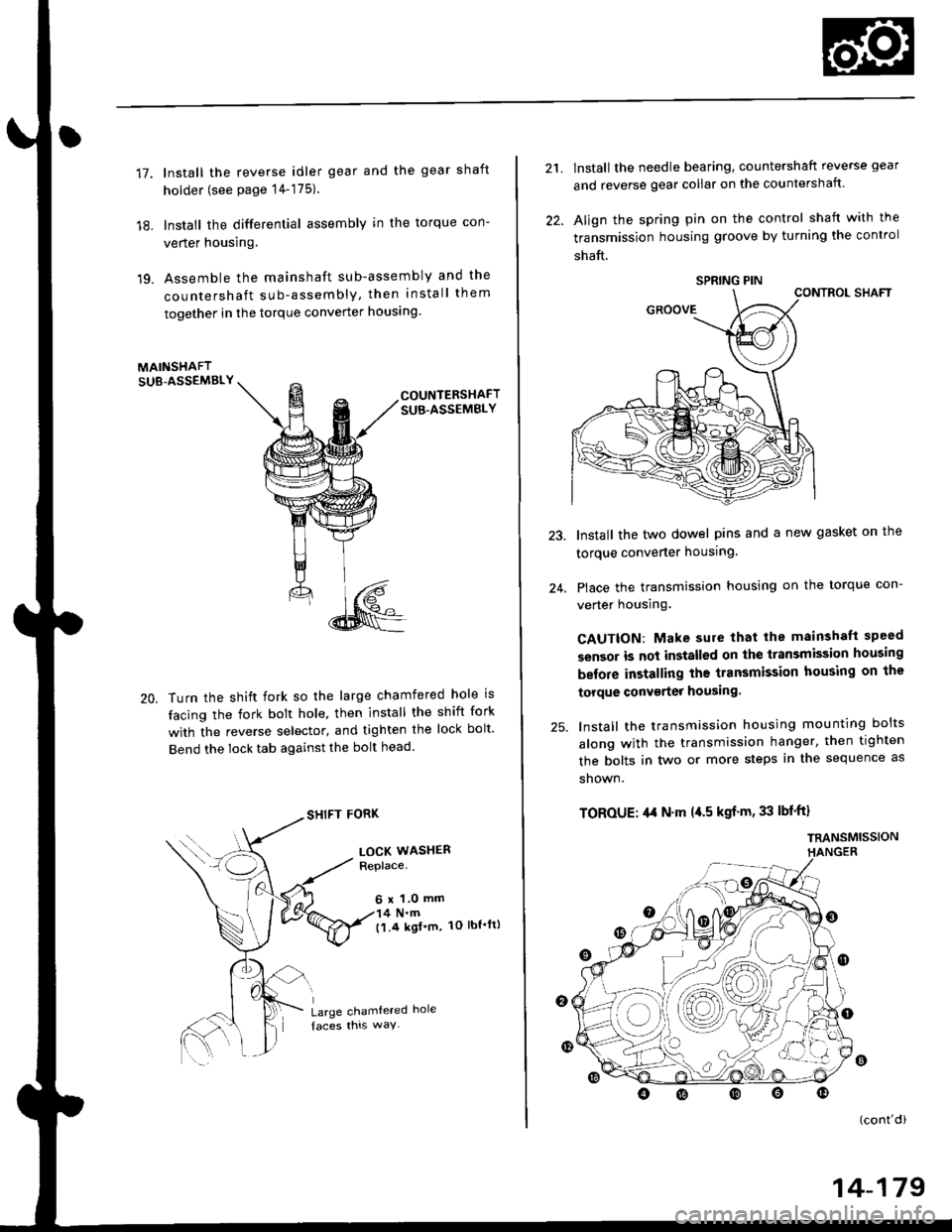
lnstall the reverse idler gear and the gear shaft
holder (see page 14-175).
lnstall the differential assembly in the torque con-
verter housing.
Assemble the mainshaft sub-assembly and the
countershaft sub-assembly, then install them
together in the torque converter houslng
MAINSHAFTSUB-ASSEMBLY
20,
COUNTERSHAFTSUB.ASSEMBLY
Turn the shift fork so the large chamfered hole is
tacing the fork bolt hole, then install the shift fork
with the reverse selector, and tighten the lock bolt'
Bend the lock tab against the bolt head
SHIFT FORK
LOCK WASHERReplace.
6 x 1.0 mm4 N.m('l.4 kgl'm, 1O lbt'ft)
Large chamtered hole
21.
22.
lnstall the needle bearing, countershaft reverse gear
and reverse gear collar on the countershaft.
Align the spring pin on the control shaft with the
transmission housing groove by turning the control
shaft.
CONTROL SHAFT
Install the two dowel pins and a new gasket on the
torque converter housing.
Place the transmission housing on the torque con-
verter housing.
CAUTION: Make sure that lhe mainshaft speed
sensor is not installed on the transmission housing
before installing the transmission housing on the
torque conv€rter housing.
lnstall the transmission housing mounting bolts
along with the transmission hanger, then tighten
the bolts in two or more steps in the sequence as
shown.
TOROUE: ,l,t N'm l{.5 kgf'm, 33 lbf'ft}
TRANSMISSIONHANGER
24.
o
(cont'di
SPRING PIN
14-179
Page 860 of 2189
Torque Converter/Drive plate
6x1.0mm12 N.m (1.2 kgt.m, 8.7 lbf.ft)
/
E PLATE
74 N.m 17.5 kgl.m, 54 lbf.ftlTorque in a ctisscaoss oattern.
@
@
L
14-182
Page 861 of 2189

Transmission
1.
lnstallation
Flush the ATF cooler as described on page l4-187
and 14-188.
Install the torque converter assembly securely with
a new O-ring on the mainshaft
STARTER MOTOR
14 mm DOWEL PIN
TOROUE O-RING
CONVERTER Replace
lnstall the starter motor on
housing, then install the two
the torque converter housing.
lil mm DOWEL PIN
the torque converter
14 mm dowsl pins in
MOUNTINGBRACKET
Place the transmission on a jack, and raise it to the
engine assembly level.
Attach the transmission to the engine, then install
two transmission housing mounting bolts and two
rear engine mounting bolts.REAR ENGINEMOUNNNG BOLTS1,1r15mm&| N.m 18.5 kgf m, 61 lbf'ft]
Replace.
64 N.m {6.547 tbf frlWASHER
ENGINE
TRANSMISSION HOUSINGMOUNTING BOLTS12 x 1.25 mm
45 N.m {4.5 kgf.m,
JACK
6. Install the transmission mount bracket.
12 x 1.25 mm6il N.m {6.5 kgf.m, a7 lbf'ft)
12 x 1.25 mm74 N.m (7.5 kgf.m,54 tbt.fr)
TRANSMISSION MOUNT
7.Install the remaining transmission housing mount-
ing bolts and remaining rear engine mounting bolt.
REAR ENGINEMOUNTING BOLT14 x 1.5 mmel N.m (8.5 kgt'm,61 tbl.ft)Replace.
HOUSING
MOUNTING BOLTS12 x 1.25 mmg N m (6.5 kgf m, 'l? lblftl
8. Remove the transmission jack.
(cont'd)
14-183
Page 862 of 2189

Transmission
Installation (cont'dl
9. Attach the torque converter to the drive plate witheight drive plate bolts and torque as follows:Rotate the crankshaft pulley as necessary to tightenthe bolts to 1/2 of the specified torque. then to thefinal torque, in a crisscross pattern.
After tightening the last bolt, check that the crank-shaft rotates freely.
TOROUE: 12 N.m {1.2 kgl.m, 8.7 tbt{r}
10 x 1.25 mm
6x1.0mm12 N.m (1.2 kgt m,8.7 rbt ft)
I 1.25 mm2/t N.m {2.4 kg{.m,17 tbt ftlCONVERTEB
10. Install the torque convener cover and the €nginestiffener.'11. Tighten the crsnkshaft pull€y bolt, if necessary (see
section 61.
12. Connect the ATF cooler hoses to the ATF cooler lines(see page 1,t192).
ATF COOIIRUNE
10 x 1.25 mma,l N.m {4.5 kgl.m,33 rbt.fttRIGHT FRONT 12 x 1.25 mmMOUNT/BRACKET 6.t N.m (6.5 kg{.m,47 tbt ftl
13. Install the right front mounvbracket.
4,r N.m 14.5 kgf.m,33 lbtft)
COVER
L,
14-1A4
SHIFT CABLE
SHIFT CAAE COVER
14. Install the control lever with a new lock washer tothe control shaft, then install the shift cable cover.
CAUION: Taks care not to bend the shift cable.
L(rcK WASHERReplace.
8 x 1,25 r'|m22N-m12.2 tgt m. 16lbnftl
x 1.0 mmtit N.m 11.4 kgt m,10 tbr,ft,
15. lnstall the exhaust pipe A.
NOTE: D16Y8 engine is shown; D16y/ engine is sim_ilar.
Replace.
GASKETReplace.
SELF.LOCKING NUTReplace.10 x 1.25 mm54 N.m (5.5 lgf.m,40 tbt ftl
NUTSELF.LOCKING NUTReplace.8 x 1.25 mm22 N.m {2.2 kgl.m, 16lbtfrl
Replace.8 x 1.25 mm16 N.m {1.6 kgI.m,12 tbf.ft)