1997 HONDA CIVIC Part number
[x] Cancel search: Part numberPage 1492 of 2189
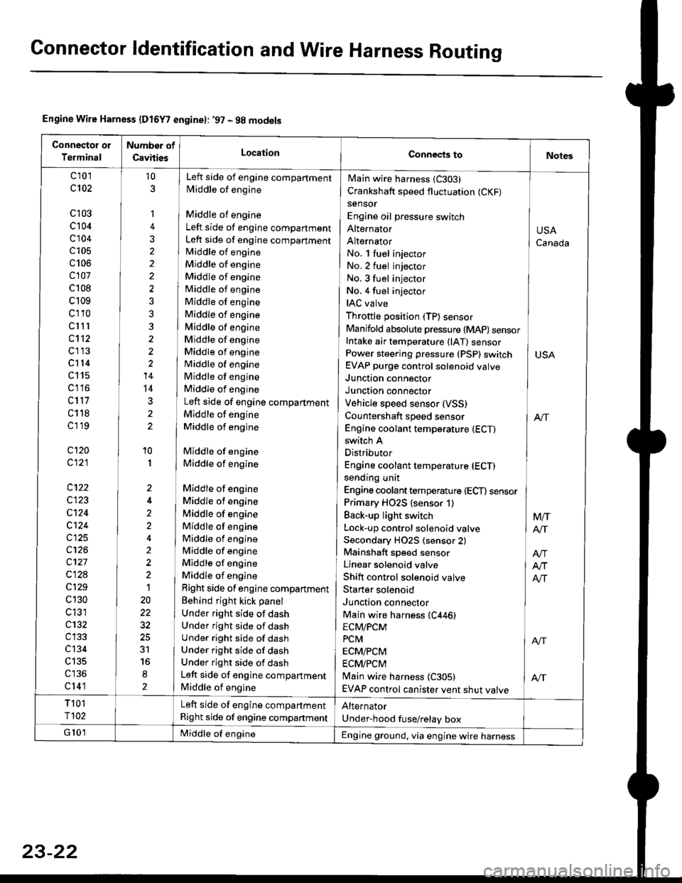
Connector ldentification and Wire Harness Routing
Engine Wire Harness {Dt6Y7 enginel: '97 - 9g models
Connectot or
Terminal
Number of
CsvitiesLocationConnects toNotes
c 101
c102
c103
c104
c104
c105
c106
c107
c 108
c109
cl10
clll
c112
cl13
cl14
c115
c1 l6
c117
c118
cl 19
cl20
c121
c122
c123
cl24
c124
c125
c126
c127
c128
c129
c 130
c 131
c132
c134
c135
cl41
10
1
2
10
I
2
2'>
4
t
20
3r
2
No. l fuel injector
No.2 fuel injector
No. 3 fuel injector INo. 4 fuel injector
IAC valve ]Throttle position (TP) sensor IManifold absolute pressure (MAP) sensorIntake air temperature (lAT) sensor ]Power steering pressure (PSp) switch I USAEVAP purge control solenoid valve
Junction connector IJunction connector IVehicle speed sensor (VSS)
Countershaft speed sensor I enEngine coolant temperature (ECTI
Main wire harness (C303)
Crankshaft speed fluctuation (CKF)
sensor
Engine oil pressure switch
Alte|'nator
Alternator
switch A
Distributor
Engine coolant temperature (ECT)
sending unit
Engine coolant temperature (ECT) sensor
Primary HO2S (sensor 1)
Back-up light switch
Lock-up control solenoid valve
Secondary H02S (sensor 2)
Mainshaft speed sensor
Linear solenoid valve
Shift control solenoid valve
Staner solenoid
Junction connector
Main wire harness (C446)
Left side of engine compartment
Middle of engine
Middle of engine
Left side of engine compartment
Left side of engine compartment
Middle of engine
Middle of engine
Middle of engine
Middle of engine
Middle of engine
Middle of engine
Middle of engine
Middle of engine
Middle of engine
Middle of engine
Middle of engine
Middle of engine
Left side of engine compartment
Middle of engine
Middle of engine
Middle of engine
Middle of engine
Middle of engine
Middle of engine
Middle of engine
Middle of engine
Middle of engine
Middle of engine
Middle of engine
Middle of engine
Right side of engine compartment
Behind right kick panel
Under right side of dash
Under right side of dash
Under right side of dash
Under right side of dash
Under right side of dash
Left side of engine compartment
Middle of engine
USA
Canada
Mtr
AIT
ECM/PCM
PcM I ArrECM/PCM
ECM/PCM
Main wire harness {C305) | AftEVAP control canister vent shut valve
T 101
r102
Left side of engine compartment
Right side of engine companment
Alternator
Under-hood fuse/relay box
G 101Middle of engineEngine ground, via engine wire harness
23-22
Page 1498 of 2189
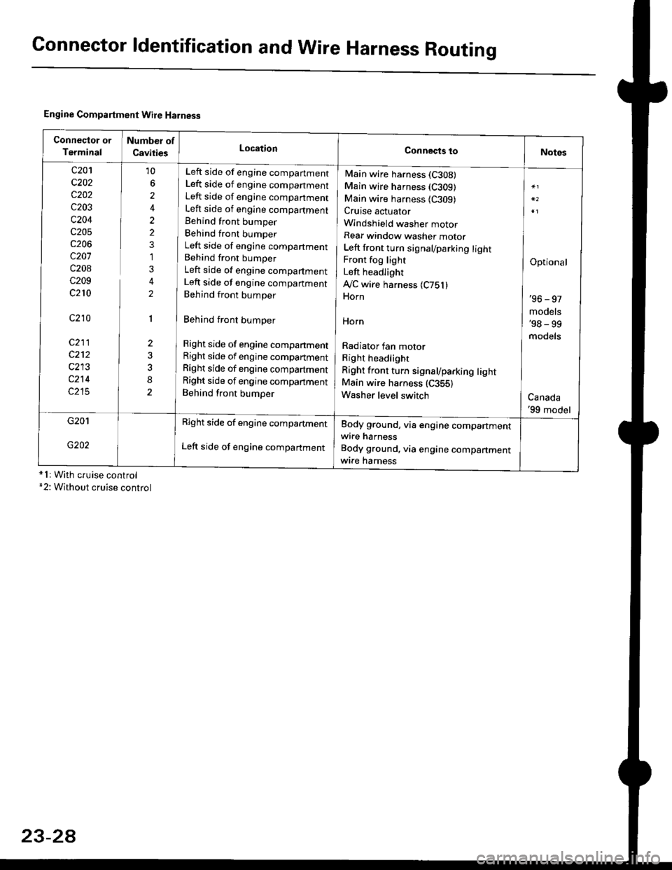
Connector ldentification and WireHarness Routing
Engine Compartment Wire Harness
conneqtor of
Terminal
Number of
CavitiesLocationConnects toNotes
c201
c202
c202
c203
c204
c205
c206
c207
c208
c209
c210
c210
c211
c212
c213
c214
c215
10
6
2
2
2
1
3
2
1
2
8
Left side of engine companment
Left side of engine companment
Left side of engine companment
Left side of engine compartment
Behind front bumper
Behind front bumper
Left side of engine compartment
Behind front bumper
Left side of engine compartment
Left side of engine companment
Behind front bumper
Behind front bumper
Right side of engine compartment
Right side of engine compartment
Right side of engine compartment
Right side of engine compartment
Behind front bumper
Main wire harness (C308)
Main wire harness (C309)
Main wire harness {C309)Cruise actuator
Windshield washer motor
Rear window washer motor
Left front turn signal/parking lightFront fog light
Left headlight
Ay'C wire harness 1C751)Horn
HOrn
Radiator fan motor
Right headlight
Right front turn signal/parking lightMain wire harness (C355)
Washer level switch
Optional
'96 - 97
models'98 - 99
models
Canada'99 model
G201
G202
Right side of engine compartment
Left side of engine compartment
Body ground, via engine compartmentwire harness
Body ground, via engine compartmentwrre harness*1r With cruise control*2: Without cruise control
23-2A
Page 1500 of 2189
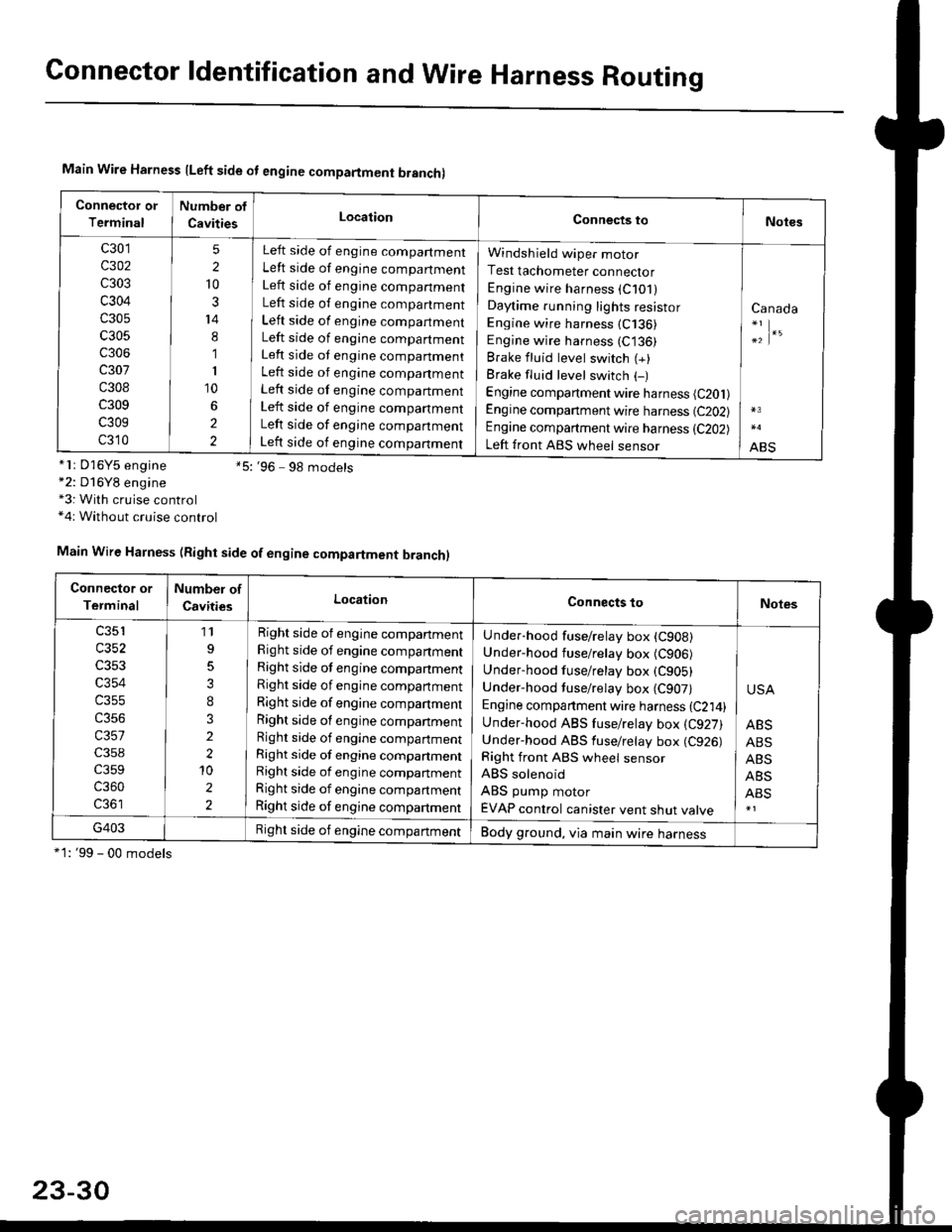
Connector ldentification and Wire Harness Routing
Main Wire Harness lLeft side ot engine compartment branchl
Connector or
Terminal
Number of
CavitiesLocationConnects toNotes
c301
c302
c303
c304
c305
c305
c306
c307
c308
c309
c309
c310
5
2
10
3
14
8
1
I
10
2
2
Left side of engine compartment
Left side of engine compartment
Left side of engine companment
Left side of engine compartment
Left side of engine compartment
Left side of engine compartment
Left side ot engine companment
Left side of engine companment
Left side of engine compartment
Left side of engine companment
Left side of engine companment
Left side of engine companment
Windsh ield wiper motor
Test tachometer connector
Engine wire harness (C101)
Daytime running lights resistor
Engine wire harness (C136)
Engine wire harness (C136)
Brake fluid level switch (+)
Brake fluid level switch (-)
Engine compartment wire harness (C201)
Engine companment wire harness (C202)
Engine compartment wire harness (C202)
Left front ABS wheel sensor
Canada
;|.'
ABS*lr D'16Y5 engine *5:'96 9g models*2: D16Y8 engine*3: With cruise control*4r Without cruise control
*1: '99 - 00 models
Main Wire Harness (Right side of engine compartment branch)
Connector or
Terminal
Number of
CavitiesLocationConnects toNotes
c353
c354
c355
c356
c357
c359
c360
11
3
I
3
2
2'10
2
2
Right side of engine compartment
Right side of engine companment
Right side of engine companment
Right side of engine compartment
Right side of engine compartment
Right side of engine companment
Right side of engine compartment
Right side of engine compartmentRight side of engine compartment
Right side of engine compartment
Right side of engine compartment
Under-hood fuse/relay box (CgoB)
Under-hood fuse/relay box (C906)
Underhood fuse/retay box (C905)
Under-hood tuse/relay box (C907)
Engine companment wire harness {C214)Under-hood ABS fuse/relay box {C927)Under-hood ABS fuse/retay box (C926)
Right front ABS wheel sensor
ABS solenoid
ABS pump motor
EVAP control canister vent shut valve
USA
ABS
ABS
ABS
ABS
ABS
G403Right side of engine compartmentBody ground, via main wire harness
23-30
Page 1754 of 2189
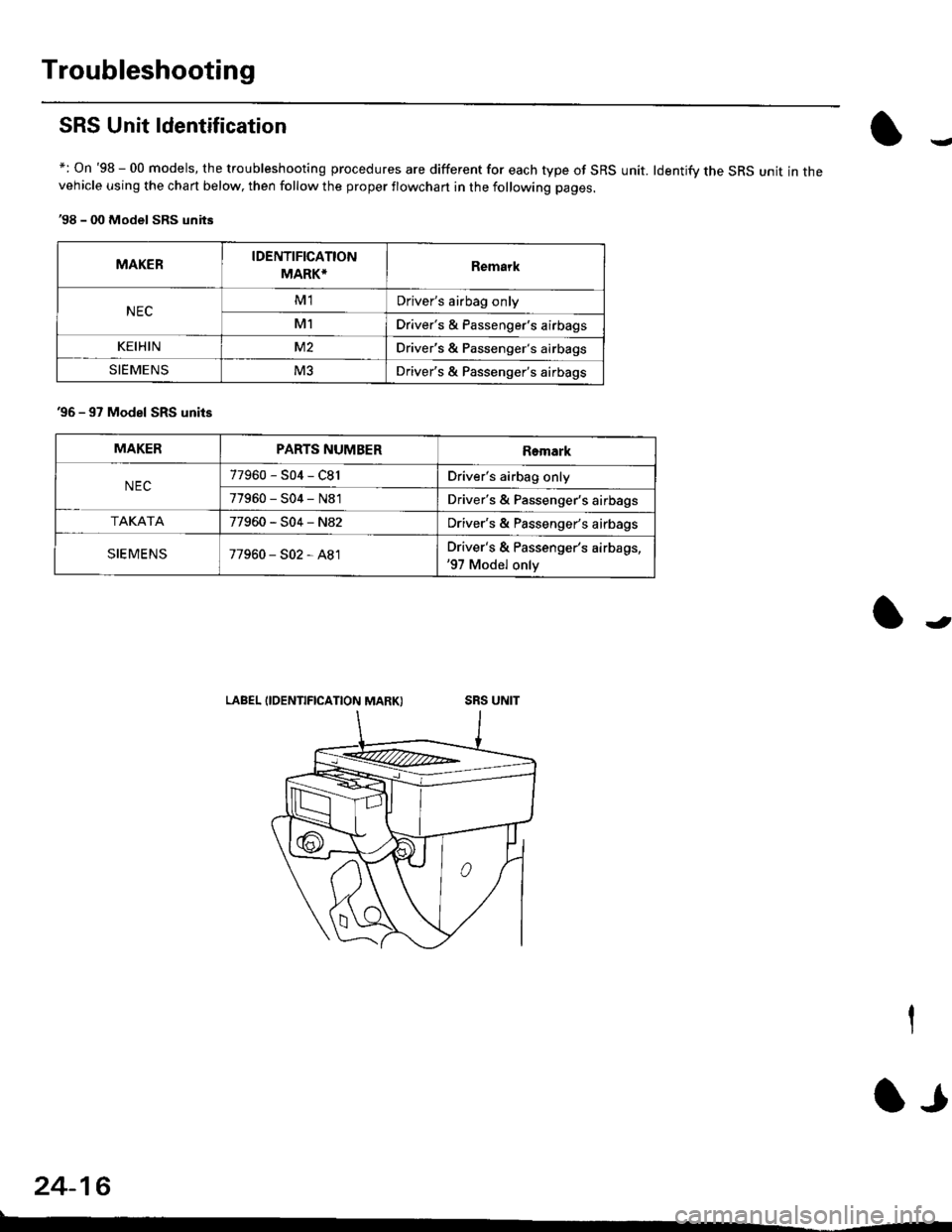
Troubleshooting
SRS Unit ldentification
+: On '98 - 00 models, the troubleshooting procedures are different for each type of SRS unit. ldentifv the SRS unit in thevehicle using the chart below, then follow the proper flowchan in the following pages.
'98 - 00 Model SRS units
MAKERIDENTIFICATION
MARK*Remark
NECM1Driver's airbag only
M1Driver's & Passenger's airbags
KEIHINM2Driver's & Passenger's airbags
SIEMENSM3Driver's & Passenger's airbags
'96 - 97 Model SRS units
LABEL IIDENTIFICATION MARK)
MAKERPARTS NUMBERRemark
NEC77960-S04-C81Driver's airbag only
77960-S04-N81Driver's & Passenger's airbags
TAKATA77960-S04-N82Driver's & Passenger's airbags
SIEMENS77960-S02-A81Driver's & Passenger's airbags,'97 Model only
24-16
lr
Page 1823 of 2189
How To Use This Manual
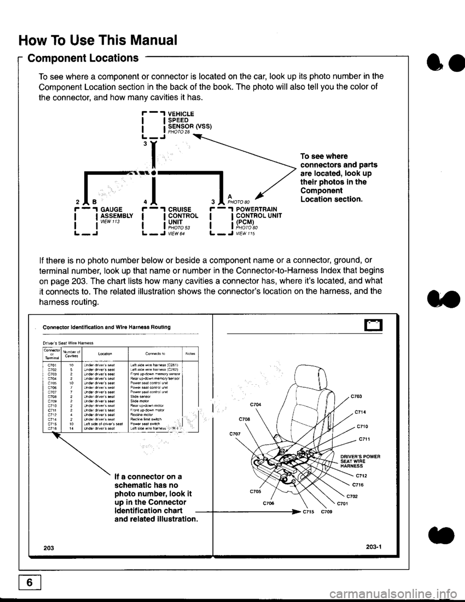
Component Locations
To see where a component or connector is located on the car, look up its photo number in the
Component Location section in the back of the book. The photo will also tell you the color of
the connector, and how many cavities it has.
To see where
connectors and parts
are located, look up
their photos in the
Component
Location section.
I
I
3
r - 1 GAUGE
| | I_S-9_EIBLY
lt''""'
r - 1 cRUtsE
! !fi':*
r - 1 POWERTRAIN
I I CONTROL UNrr
a i[i9#r,
lf there is no photo number below or beside a component name or a connector, ground, or
terminal number, look up that name or number in the Connector-to-Harness Index that begins
on page 203. The chart lists how many cavities a connector has, where it's located, and what
it connects to. The related illustration shows the connector's location on the harness, and the
harness routing.
Connactor ldontlticallon and Wke Harness Rouling
DFIVEF'S POWERSEAT WIAEHAFNESS
It a connector on a
schematic has no
photo number, look it
up in the Connector
ldentilication chart
c712
c7t6
c702c701
and related illustration.
203203.1
Drlvor s Sea! wne Harn€ss
Lefts'd.Hrc hatu$ 1c2611Loft s'd. src hamass 1c262)
F6ar up.dow^ n.morykisor
l
E
oo
Page 1824 of 2189
Connector Views
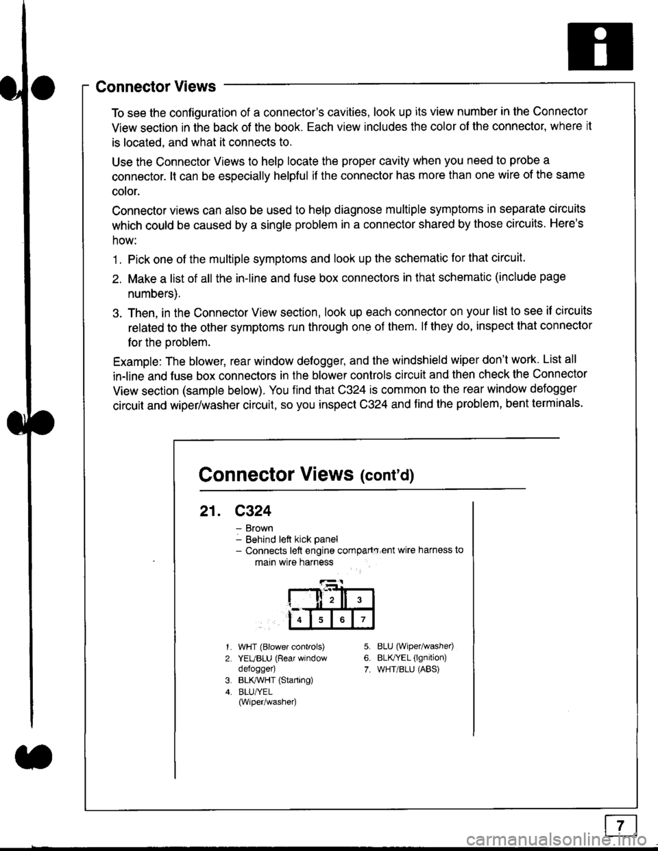
To see the configuration of a connector's cavities, look up its view number in the Connector
View section in the back of the book. Each view includes the color of the connector, where it
is located, and what it connects to.
Use the Connector Views to help locate the proper cavity when you need to probe a
connector. lt can be especially helpful if the connector has more than one wire of the same
cotor.
Connector views can also be used to help diagnose multiple symptoms in separate circuits
which could be caused by a single problem in a connector shared by those circuits. Here's
how:
1. Pick one of the multiple symptoms and look up the schematic for that circuit.
2. Make a list of all the in-line and fuse box connectors in that schematic (include page
numbers).
3. Then, in the Connector View section, look up each connector on your list to see il circuits
related to the other symptoms run through one of them. lf they do, inspect that connector
for the oroblem.
Example: The blower, rear window defogger, and the windshield wiper don't work. List all
in-line and fuse box connectors in the blower controls circuit and then check the Connector
View section (sample below). You find that C324 is common to the rear window defogger
circuit and wiper/washer circuit, so you inspect C324 and find the problem, bent terminals.
5.
6.
7.
1.
2.
WHT (Blower controls)
YEUBLU (Rear window
defogger)
BLK,ryVHT (Starting)
BLU/YEL(Wiper/washe0
8LU (Wiper/washed
BLfiEL (lgnition)
WHT/BLU (ABS)
Connector Views (cont'd)
21. C324
Brown
Behind left kick panel- Connects left engine compartry'ent wire harness to
main wire harness
ll,ll,
567
Page 1826 of 2189
Connectors - "C"
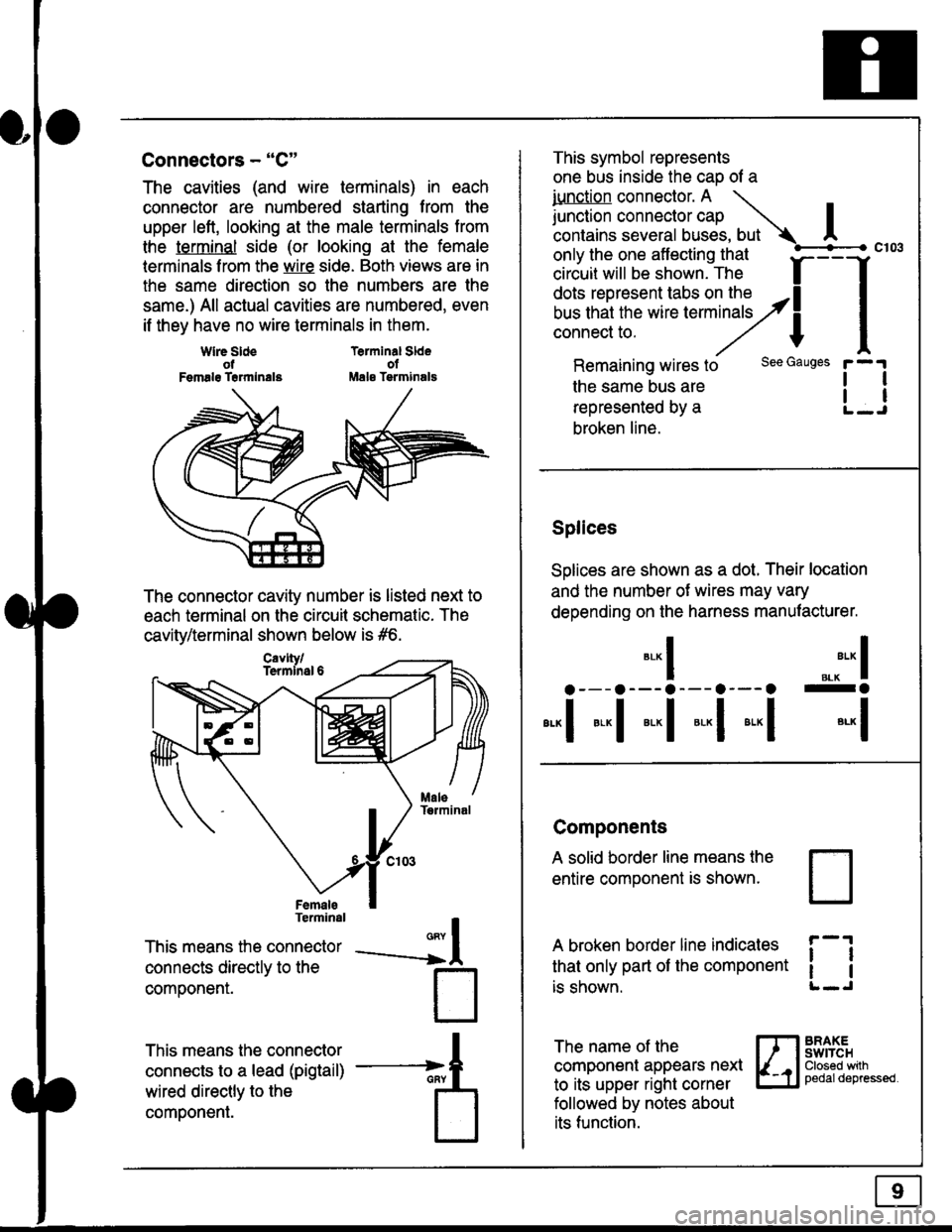
The cavities (and wire terminals) in each
connector are numbered starting from the
upper left, looking at the male terminals trom
the terminal side (or looking at the female
lerminals f rom the wire side. Both views are in
the same direction so the numbers are the
same.) All actual cavities are numbered, even
if they have no wire terminals in them.
Terminal SldeolMale Tsrminals
{
T
_A
Wlre SldeotFemalg Trrmlnala
The connector cavity number is listed next to
each terminal on the circuit schematic. The
cavity/terminal shown below is #6.
Terminal
This means the connector
connects directly to the
componenr.
This means the connector
connects to a lead (pigtail)
wired directly to the
component.
Cavlty/Termlnsl 6
only the one affecting that
ciriuit will be shown. The f
--f
!!*!"*F"#fi5'�;,Hy4
I
Remaining wires to
the same bus are
represented by a
broken line.
The name of the
component appears next
to its upper right corner
followed by notes about
its function.
This symbol represents
one bus inside the cao of a
iunction connector. A \
lr"ctb. connectorcap |contains several buses, but Ac103
tl
tl
*-
I ",.-"* I
a---a---a--- a--- o -a
*"1 *-l *-l *-l *"1 *-l
See Gauges
Splices
Solices are shown as a dot. Their location
and the number of wires may vary
depending on the harness manufacturer.
Components
A solid border line means the
entire component is shown.
A broken border line indicales
that only part of the component
is shown.
t_J
ll
ll
BRAXEswtTcHClosed wilhpedaldepressed.
Page 1827 of 2189
How To Use This Manual
Symbols
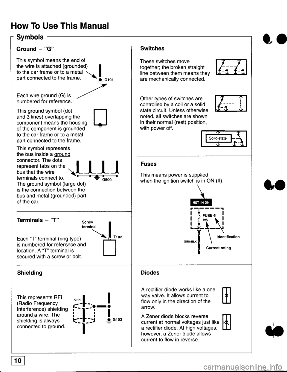
Ground - "G"
This symbol means the end ol
the wire is attached (grounded) Ito the car frame or to a metal I
part connected to the frame. \i oro,|
-t'
Each wire ground (G) it --/
numbered for reference.
oo
Switches
These switches move
together; the broken straight
line between them means the,
are mechanically connected.
Other types of switches are
controlled by a coil or a solid
state circuit. Unless otherwise
noted. all switches are shown
in their normal (rest) position,
with power off.
This ground symbol (dot
and 3 lines) overlapping the
component means the housing
of the component is grounded
to the car frame or to a metal
part connected to the frame.
This symbol represents
the bus inside a ground
connector. The dots I
i:l*,':1,'^:*,:"
;"
r"L I I I
terminals connect to.
The ground symbol (large dot)
is the connection between the
bus and metal (grounded) part
of the car.
Terminals - "T"
ffi
ffi
Solid-state
Fuses
This means power is supplied
when the ignition switch is in ON (ll).
Current rating
Diodes
A rectifier diode works like a one
way valve. lt allows current to
llow only in the direction of the
arrow.
A Zener diode blocks reverse
current at normal voltages just like
a rectifier diode. At high voltages.
however, a Zener diode allows
current to f low in reverse
oo
Each "T" lerminal (ring type)
is numbered for reference and
location. A "T" terminal is
secured with a screw or bolt.
Shielding
This represents RFI
(Radio Frequency
Interference) shielding
around a wire. The
shielding is always
connected to ground.
f--l;j-i",..
I
,,,,
T