Page 1840 of 2189

Ground-to-Components I ndex
f.,lONOTE: All ground wires are BLK unless otherwise noted.
GroundPageComponents or Circuit Grounded
Battery (BLKYEL)
Steering pump bracket
t+-rg ITransmission housing
l
G101
(-1)
G101
(-2)
14-2
and
14-3
ano
14-1
Powertrain or engine control module (PG1 and pG2 are BLK: LG1 and LG2 are
BRN/BLK), EGR control solenoid valve (CW, EGR valve and lift sensor (Dt6yS enginewith M,/T), Engine coolant temperature switch, pGM-Fl main relay, power steeringpressure switch (USA), Primary HO2S (D16Y5 engine with l\/,/T), Vehicle speed sensor,VTEC pressure switch (D16Y5/D16Y8 engines), CKF sensor (BRN/BLK), Transmission
control module (CYf) (Pc1 is BLK: LG1 is BRN/BLK)
Shielding betvveen the PCM or ECM and these components (all have BRN/BLK wires):
CKF sensor, TDC/CKP/CYP sensor. Primary and secondary heated oxygen sensors.
Knock sensor (CWDl6YB engine), Mainshaft speed sensor (AiT except CVT),
I Countershaft speed sensor (A/T except CVf)
Shielding between the TCM and these components (CVT) (all have BRN/BLK wires):
Drive pulley speed sensor, Driven pulley speed sensor, Secondary gear shaft
speed sensor
Powertrain or engine control module (PG1 and pG2 are BLK; LG1 and LGz are
BRN/BLK), EGR control solenoid valve (D16Y5 engine), EGR valve (Dt685), Engine
coolant temperature switch, Fuel pressure regulator shut-off solenoid valve (D1685),
PGM-FI main relay, Power steering pressure switch (USA), Vehicle speed sensor, VTECpressure switch (All except D16Y7 engine), CKF sensor (A
except 81642) (BRN/BLK)
Shielding between the PCM or ECM and these components (all have BRN/BLK wires):
CKF sensor, TDC/CKP/CYP sensor, Primary and secondary heated oxygen sensors,
Knock sensor (All except D16Y7 engine), i/ainshaft speed sensor (Arf except CW),
Countershaft speed sensor (A,/T except CVf), Drive pulley speed sensor (CW), Drivenpulley speed sensor (CVT), Secondary gear shaft speed sensor (CVf)
I Badiator fan motor, Right front parking/turn signat tight, Right headtight
G20214-4I Cruise control actuator, Left front parking/turn signal lights, Left headlight, Rear window
I washer motor, Windshield washer motor, Washer fluid level switch (,99-'00 Canada)
G401| +-o
and
14-7
Accessory power socket, Brake fluid level switch, Clutch interlock switch (M/T), Clutchswitch (lillT with cruise/D16Y5 engine with MfD, Combination wiper switch (Z wires),
Cruise control main switch, Cruise control unit, Dash lights brightness controller, Data
link connector, Daytime running lights control unit (Canada), Gauge assembly, Horn('96-'97 models), Integrated control unit, Interlock control unit (ArI), Keyless door lock
control unit ('99-'00 models with keyless), Moonroof close and open relays, Moonroof
switch, Park pin switch (A/r), Power window relay, Rear window defogger relay, Rear
window defogger switch ('96-'98 models), Steering lock, Stereo radio tuner (,96-,98
USA: LX, EX, and HX), Turn signal/hazard relay, Windshield wiper motor.....plus
everything grounded through G402
6-6
Page 1855 of 2189
ie----1
\{
i____J
WIIT/FED
FUSE 54OPNOI404
c351
vtEw 34
c419
FUSE 52HOAT. ST(IP LT154
c352
vlEw2/
FUSE 53NAZABO
c352
vtEw 27
c4't 1
UNDER-HOODFUSE/RELAYgox
15
_",":IWH'/BLK
(Not (Not 7Used) Used)
UNDER-DASHFUSE/RELAY BOXPHOTA 58
c419 C926110!0,63 oPTtoNCONNECTOBPHOTO 62
WHT/GRN
{with CruiseControl 4)
WHT
'9&'98 modelspre'wked toracteEsorysacurity system
""'l
o
;l10
vtEw 6a
cs16
'99'0O modelspre-wired foraccessorysecurfy system
SECURIrySYSTEMCONNECTOR(oPTroN)Page 133-4
ll
tl
BRAKESWITCHPages 23-4 , 24 4 ,25-4, 34-1, 39,39-4, 39-8, 39-12,44-2,110-15,110-16, 110 17,'138, and 138-1
ll
ll
HAZARDWARNINGswrTcHPage 110'6or 110-8vtEw 32
,rr rrRt3,:i]L-
SECURITYSYSTEMCONNECTOR(oPTlON)Page 133-4
r----=-:'l
I Uoll UonEcI I
tlL------JHORN BELAYPage 40, 40-1,ot 40-2
PHOTO 58 (96 97 models)PHOIo 129 (98 mode)
c447
wEw 5a
sEcuRrwSYSTEMCONNECTOR(oPTroN)Page 133
10-13
Page 1939 of 2189
Horn
- '96-'97 Models
UNDER.HOODFUSE/RELAYBOX
c353PHOTOs
See PowerOistribution,pag610-13.""^T.!,-
HORNRELAYPHA|O 58
c214
vtEw21
BLU/FEO
1
VHT/qRN
I1
WHT/qRN
: :i-I:::--li i ! !'-'! fevtess
! a;fi."*
,,lr--J I::.-------J. , STEREO RAOIO TUNER
| | vtEw 68
HORN
l
h: c4o1PHQ|A 57
c430
Sse CruiseControl
Vehicles pre-wired ---lor accessorysecurity system
BLU
GBY
------- J
- -.! STEERINGWHEEL
6 g c411
| _vtEw 60
a,---li
cnv I
18 A C516
sEcuRtwSYSTEMCONNECTOR(oPTroN)PHO|O 73VEW 5A
40
Page 1940 of 2189
- '98 Model
FUSE 52floFft,sroP tT154
UNDER.HOODFUSE/RELAYBOX
THI
I
I
I
c353I Y C3s2
""',o"n I il?lo,'wHT/cFN U
@.S€o PowslDisfibdion,page 1013.
HORNRELAY
o
GFY
87
:l;l
:l'l
!'Gi-'! c.oMBrNAroN
I UIio | !!9f1Ii swrrcH
GBY
2
ELU
I
I
I
iq!ffi"
a*
:t
40-1
L-- -- - --
Page 1941 of 2189
Horn
- '99-'00 Models
FUSE 52HORI,SfOP LTt5a
UNDER.HOODFUSE/RELAYBOX
HORNRELAY
2
BIU/FED
Ior
GRY
.,1 ,
J---a-----r---O
i ;l i ;,1...,' r--1 : SECUR|TY:ll:sYsrEM,ia,coNNEcroR' ! ! (oPrloN), L--J , i!,o!o 73, KEYLESS I vlEw 58
: DooR LocK withi coNTRoL Kevless, UNIT EntryI PHOIO 134I vtEw 75
i o.--------;
:T:' cnvl :
i"l ii ri-'--.| coMBtNATtoN
: lrft ! !',f,11" I' | | puotozz :', l--J vttw u ;
i--- Er""pt ex.ooer ----j
c214
v|EW21
c430PHOTO 65
Vehicles pre-wired foraccessory security system
STEERINGWHEEL
CABLEREEL
.l
I
I
I
ISee CruiseControl
GRY
ELU
I
a\
I
GRY
HORN
---------^1
niffil"a!m"
40-2
Page 2028 of 2189

Power Door Locks (cont'd)
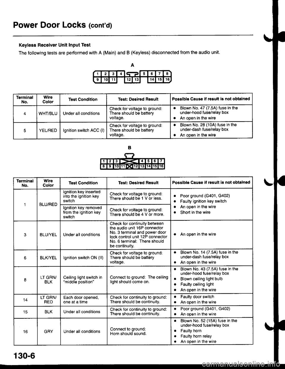
Keyless Receiver Unit Input Test
The following tests are pertormed with A (Main) and B (Keyless) disconnected from the audio unit.
TerminalNo.WireColorTest ConditlonTest: Desired RasultPossible Cause it resull is not obtained
4WHT/BLUUnder all conditionsCheck for vollage to ground:
There should bs batteryvoltage.
aBlown No. 47 (7.5A) tuse in the
under-hood fuss/relay box
An open in the wireo
5YEUREDlgnition switch ACC (l)Check lor voltage to ground:
Th€re should be battery
voltage.
aBlown No. 28 (10A) fuse in the
underdash fusg/relay box
An open in the wirea
TerminalNo.WireColorTest CondiiionTest: Desired ResultPossible Cause if rssult i3 not obtalned
BLU/RED
lgnition key insertedinto the ignition key
switch
Check for voltage to ground:
There should bs 1 V or less.aPoor ground (G401, G402)
Faulty ignition key switch
An open in the wire
Short in the wire
a
a
algnition key r€moved
trom the ignition key
switch
Check lor voltage to ground:
There should be 4 V or more.
3BLUI/ELUnder all conditions
Check for continuity betweenthe audio unit 16P connectorNo- 3 terminal and power doorlock control unit 12P connsctorNo. 6 terminal: There should
be continuity.
I An open in the wire
6BLK/YELlgnition switch ON (ll)Check for voltage to ground:
Thers should be batteryvollage.
. Blown No. 14 (7.5A) fuse in the
under-dash fuse/relay box
. An open in the wire
8LT GRN/BLKCeiljng light switch in"middle position"Connect to ground: The ceilinglight should come on.
aBlown No. 43 (7.5A) fuse in the
undsr-hood fuse/relay box
Blown ceiling light bulb
Faulty ceiling light
An open in the wire
a
a
o
14LT GRN/REDEach door oponed,one at a timeCheck for continuity to ground:
There should be continuity.
aFaulty door switch
An open in lhe wirea
tcBLKUnder all conditionsCheck for continuity to ground:
There should b€ continuity.
aPoor ground (G401, G402)
An open in the wirea
16GRYUnder all conditionsConn€ct to ground:
Horn should sound.
. Blown No.52 (15A) fuse in the
under-hood tuse/relay box
. Faulty horn
. Faulty horn relay
. An open in the wire
130-6
Page 2034 of 2189
Power Door Locks
- '99-'00 Models with Keyless Entry
@
i-f?G;.-----l
i ?f*""t:::", i
L-,H-i{*q-J
UNDER-DASHFUSE/RELAYBOX
8 Y C419
vtEW49
SeeHOrns
15
Horncontrol
Grgund
lgnltioninputDooropeninput
K€yswitchInpul
Lighlstlashcontrol
17
ALK
c447
vtEw 5a
'12
LT GFN/RED
See GroundDistribution,page I +6,
YI
IF--.--.r-G401
I
3
ALU/f,EO
!r.lFN' z sEcuglw t5REOSYSTEMtsb'*nii'cro* =2
a, o"nt"ao 1lvlEw 58
(Not
(oPTroN) c447See HeadlightSwitch
C415 STEERINGPHora 6a LOCKVlEtt\/ 14 PHO|O 71
lgntlion KaySYrftchClosed with keyin ignition.
LT GRN/FED
LT GFN/REDSee lgnitionKey Reminder
UNDER-DASHFUSE/RELAYBOX
ALU/IVITT
a9
GFN
'14
GRN
130-12
Page 2038 of 2189

Power Door Locks (cont'd)
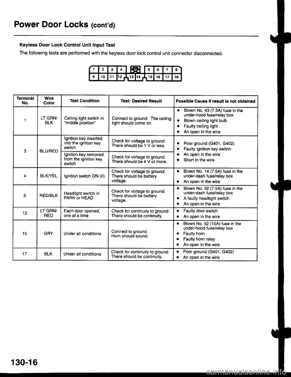
Keyless Door Lock Control Unit Input Test
The following tests are performed with the keyless door lock control unit connector disconnected.
TerminalNo.WireColorTest ConditionTest: Desir€d ResultPossible Cause if result ls not obtain€d
1LT GRN/BLKCeiling light switch in"middle position"Connect to ground: The ceilinglight should come on.
aBlown No. 43 (7.5A) luse in theunder-hood tuse/relay box
Blown ceiling light bulb
Faulty ceiling light
An open in the wire
o
a
a
3BLU/RED
lgnition key insertedinto the ignition keyswitch
Ch€ck lor voltage to ground:There should be I V or less.aPoor ground (G401, G402)
Faulty ignition key switch
An open in the wire
Short in the wire
a
a
o
lgnition key removedlrom the ignition keyswitch
Check for voltage to ground:There should be 4 V or more.
BLfiEtlgnition switch ON (ll)Check lor voltage to ground:
There should be batteryvoltage.
. Blown No. 14 (7.54) fuse in theunder-dash fuse/relay box
. An open in the wire
bREO/BLKHeadlight switch inPARK OT HEAD
Check for voltage to ground:
There should be batteryvoltage.
aBlown No. 32 (7.5A) luse in theunder-dash fuse/relay box
A faulty headlight switch
An open in the wire
a
o
LT GRN/RED
Each door opened,one at a timeCheck lor continuity to ground:
There should be continuitv.
oFaulty door switch
An open in the wireo
15GRYUnder all conditionsConnect to ground:
Horn should sound.
. Blown No. 52 (154) fuse in theunder-hood fuse/relay box
. Faulty horn
. Faulty horn relay
o An open in the wire
BLKUnder all conditionsCheck lor continuity to ground:
There should be continuity.
aPoor ground (G401 , G402)
An open in the wirea
130-16