Page 507 of 2189

Fuel Supply System
PGM-FI Main Relay (cont'dl
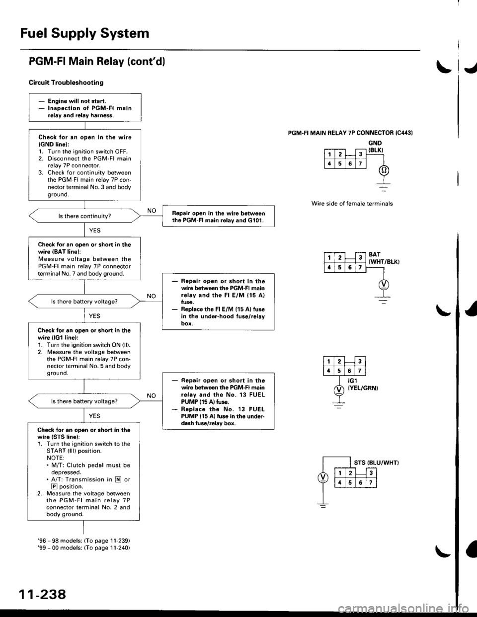
Circuit Troubleshootin g
PGM.FI MAIN RELAY 7P CONNECTOR {C443)
GND{8LK)
Wire side of female terminals
/BLK}
- Engine will not start.- lnsoection of PGM-FI mainrelay and relay harne$.
Check for an open in the wire{GNO line}:l. Turn the ignition switch OFF.2. Disconnect the PGM-Fl mainrelay 7P connector.3. Check for continuity betweenthe PGM Fl main relay 7P con-nector terminal No.3 and bodyground.
Ropai. open in the wir€ betweenthe PGM-FI main .elav and G101.
Check for an open or short in thewire {BAT lin€}:N4easure voltage between thePGM-FI main relay 7P connectorterminal No. 7 and body ground.- Repair open or sho.t in thewire between the PGM-FI mainrelay and the Fl E/M {15 A}fus€.- Replace the Fl E/M (15 Allu3ein the under-hood fuse/relayoox.
ls lhere battery voltage?
Check tor an open or short in thewire {lGl line):1. Turn the ignition switch ON (ll).
2. Measure the voltage betweenthe PGM-Fl main relay 7P con'nector terminal No. 5 and bodyground.- Repair open or short in thewire betwoen the PGM-FI mainrelav and the No. 13 FUELPUMP (15 A)tuse.- R€place the No. 13 FUELPUMP {15 A} tus€ in the under-d.sh fus€/relay box.
ls there battery voltage?
Ch.ck for an open or short in thewire {STS lino}r1. Turn the ignition switch to theSTART (lll) position.NOTE:. M/T: Clutch pedal must beoepresseo.. A/T: Transmission in E or
E position.2, Measure the voltage betweenthe PGM-Fl main relay 7Pconnector terminal No, 2 andbody ground.
12
[,a567
123BAT
{WHTa56,
'96 98 models: (To page 1l 239)'99 - 00 models: (To page I l-240)
11-238,
Page 508 of 2189

JI
I
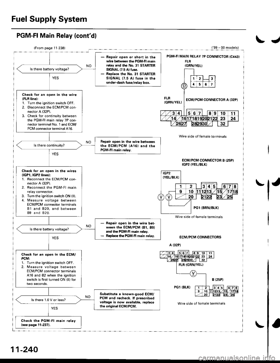
- Repair open or 3hort in the
wire bstw€er the lGM-Fl mainrolsy .nd the No. 31 STARTERSGNAL 17.5 A) tuse.- Reolace the No. 31 STARTER
SIGNAL (7.5 Al fu3o in the
unde.-dash tusg/rolav box.
ls there baftery voltage?
Chock lor !n open in the wit.
lFLn line)l1. Turn the ignition switch OFF
2. Disconnect the ECM/PCM con-
nector A (32P).
3. Check for continuity between
the PGM-FI main relay 7P con-
nectorterminal No. 1 and ECM/
PCM connector terminal A16.
Ropair op6n in th. walo betwoanthe ECM/PCM lA16) and thc
PGM-FI main rolaY.
Ch6ck for an opon in th. wi.e3
llcPl,lGP2linesl:1. Reconnect the ECM/PCN4 con-nector A (32P).
2. Reconnoct the PGM-Fl main
relay connector,3. Turn the ignition switch ON (ll)
4. Measure voltage between
ECM/PCM connector termanals
A11 and A10, and betweenA24 6nd A10.
Repeir opon in th6 wire bet-
ween ttre ECiA /PCM (A11, A24)
and tho PGM-FI msin r.lty.
R€plac. tho FGM-FI main rc|.Y.
Check tor an open in the ECM/
PCM:1. Turn the ignition switch OFF.
2, Measure voltage between
ECM/PCM connector terminalsA16 and A10 when the ignition
switch is lirst turned ON (ll) for
two seconds.
Substituta a known-good ECM/
PCM and rechcck. lf proacribod
voltege is now availablc, r.Placethe originll ECM/PCM.
ls thero 1.0 V or less?
Ch6ck th. PGM-FI m.in lolay(.ee pagc 11-2371.
('96 - 98 models)
t32Pt
Wire side of female terminals
IGP2{YEL/BLKI
FLRIGRN/YELIPGl
3l5 6 7l lslel tl1l
1213'tal5t6't7t8t920221 232a
2527284t
(cont'd)
1 1-239
IBLK)
{GRN/YELI
FLR(GRN/YELI
23
()a6t
ECM/PCM CONNECTOR A
21Il0t1
12r31'al5't61'tti9ml,/x2232a
25212e293ol./
PGl (BLK)
1I
12't/t15t617t8t9zi
25272A4t304l
Page 509 of 2189

Fuel Supply System
- Repair op€n or short in thewir€ betlveen the PGM-FI mainrelay and the No. 31 STARTERSIGNAL 17.5 A) fuse.- RoDlace the No. 31 STARTERSIGNAL {7,5 Al tuse in theunder-dash luse/rolay box.
ls there battery voltage?
Check tor an open in the wire(FLR linel:1. Turn the ignition switch OFF.2. Disconnect the ECM/PCM con-nector A (32P).
3. Check for continuity betweenthe PGM-FI main relay 7P con-nector terminal No. 1 and ECM/PCM connector terminal A16.
Repair open in the wir6 botweenthe ECM/PCM (A161 and rhePGM-FI main relay.
Check for an open in the wires{lGPl, lGP2 line3):1. Reconnect the ECM/PCM con-nector A {32P).2. Reconnect the PGM-Fl mainrelay connector.3. Turn the ignition switch ON (ll).
4. Measure voltage betweenECN4/PCM connector terminals81 and 820, and betweenBg and 820.
- Repair open in the wire bet-ween th. ECM/PCM (81, Bg)snd the PGM-F main rolay.- Roplace th€ PGM-FI main relav.
Chock tor an open in th6 ECM/PCM:1. Turn the ignition switch OFF.2. Measure vo ltage betweenECM/PCM connector terminalsA16 and 82 when the ignitionswitch is first turned ON lll) for
Sub3titute . known-good ECM/PCM and rochock. lf prescribedvohege is now available, replacethe original ECM/PCM.
ls there 1.0 V or less?
Chock the PGM-Fl m.in r6lay{see p.ge 11-2371.
PGM-FI Main Relay (cont'd)
_._(9x . qq -gqerll _
PGM.FI MAIN FELAY 7P CONNECTOR {C4€}FLR
ECM/PCM CONNECTORS
A (32P1
Wire side ot female terminals
Wire side of fem6le terminals
ECM/PCM CONNECTOR B {25PIIGP2 {YEL/BLKI
IGRN/YEL}
IGP2(YEL/BLKI
Wire side of female terminals
11-240
IJ
'l'
Page 510 of 2189

IFuelTank
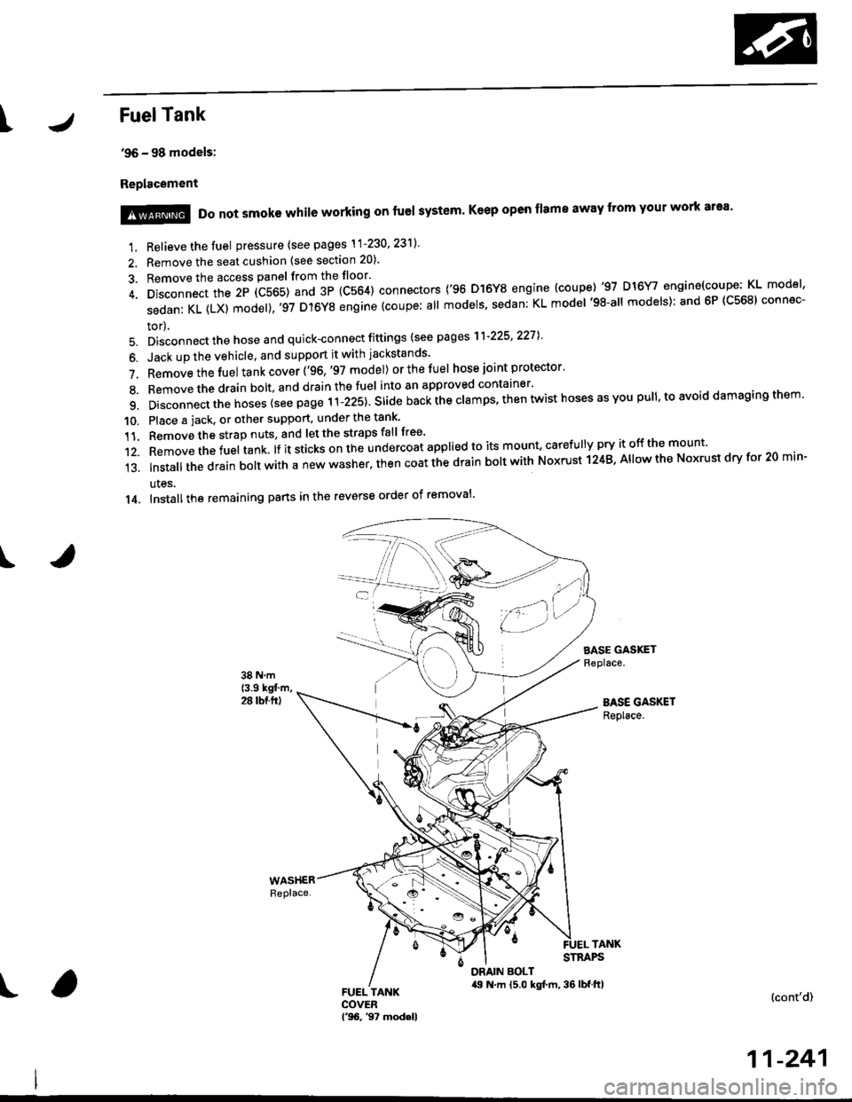
'96 - 98 models:
Replacement
I
1. Relieve the fuel pressure (see pages \1-230' 23'll'
2. Remove the seat cushion (see section 20).
3. Remove the access panel from the floor'
4. Disconnect the 2P (C565) and 3P (C564) connectors ('96 D]6Y8 engine (coupe) '97 D16Y/ engine(coupe: KL model'
sedanKL(LX)model).'97D'l6YSengine(coupe:allmodels'sedan:KLmodel'98-allmodels):and6P(C568)connec-
tor),
5. Disconnect the hose and quick-connect fittings (see pag es'l'l-225' 2271
6. Jack up the vehicle, and support it with jackstands'
7. Removethefuel tank cover ('96,'97 model) orthefuel hose joint protector'
8. Bemovethedrain bolt,and drainthefuel into an approved container'
9. Disconnect the hoses {see page r i-izst. Sria" nu"i ihe clamps, then twist hoses as you pull, to avoid damaging them'
10. Place a jack. or other support, under the tank'
11. Remove the strap nuts, and let the straps fall free'
12. Removethefuel tank lf it sticks on the undercoat applied to its mount' caref u lly pry it off the mount'
13.|nsta||thedrainbo|twithanewwasher.thencoatthedrainbo|twithNoxrustl24B,A||owtheNoxrustdryfor20min-
ules.
14. Installthe remaining pans in the reverse order of removal'
SASE GASKETReplace.
BASE GASKETReplace.
!@@ Do not smoke while working on fuel system' Keep open flame away from your work ar'a'
TANKSTRAPS
DRAIN BOLT,19 N.m {5.0 kgt m, 36 lbf.ftl(cont'd)
11-241
Page 511 of 2189

Fuel Supply System
Fuel Tank {cont'dl
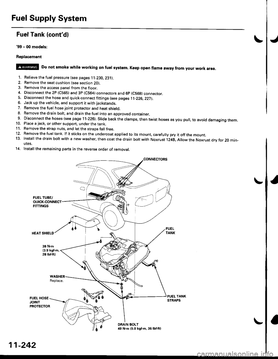
39 - (xt models:
Replac6ment
o
@ Do not smoke whire working on fuer system. Ke€p open frama away trom your work area.
1. Relievethefuel pressure (see pages 11-230,23'll.
2. Remove the seat cushion lsee section 2O).3, Remove the access panel fromthefloor.
4. Disconnectthe2P (C565) and3P(CS64) connectors and 6p (C569) connecror.5. Disconnect the hose and quick-connect fiftings (see pages 1l-226,22j),6. Jack up the vehicle, and support it with jackstands.
7. Removethefuel hose joint protector and heat shield.8. Removethedrain bolt. and drainthefuel intoan aporoved container.9 Disconnect the hoses (see page 11-226). Slide back the clamps. then twist hoses as you pull, to avoid damagtng rnem.10. Place a jack, or other support, under the tank,11. Remove the strap nuts, and let the straps fallfree,'12. Removethefuel tank. lf itsticks onthe undercoat applied to its mount, carefully pry itoffthe mount.13. Install thedfain boltwith a new washer. then coat the d rain bolt with Noxrust 124B,Allowthe Nox.ust drv for 20 min-utes.
14. Installthe remaining parts in the reverse order of removal,
Replace.
DRAIN BOLT,19 N.m (5.0 kgf.m, 36lbf.ft)
11-242
Page 512 of 2189
Intake Air System
\JSystem DescriPtion
The system supp|ies air for a|| engine needs' |t consists of the intake air pipe' Air C|eaner (ACL}, intake air duct, Thrott|e
Body (TB), ldle Air control (lAc) valve and intake manifold. A resonator in the intake air pipe provides additional silencing
as air is drawn into the system.
D16Y5, D16Y8, 816A2 engine {M/Tl
YEL/ - From PGM-FIaLK - MA|N RELAY
BLK/BLU
-- ORN
INTAKEAIRDUCT
IROTARYIIAC VALVE
Iaru
ENGINECOOLANT
BLK/
INTAKEAIR DUCT
I
D16Y5 engine (CVT), D16Y8 engine (A/T)' f'ttlxr ,tla"tpoto
D16Y7 engine:
{ROTARY)IAC VALVE
VARIOUSSENSORS
INTAKEAIRPIPE
tr
RESONATOR
!r,
IAC VALVE
BLK
11-243
Page 516 of 2189

IThrottle BodY
Description
The throttle bodY is either a single-barrel side-draft type
(D16Y5, D16Y8, 816A2 engine) or a down-draft type
(D16Y/ engine). The lower portion ot the throttle valve is
heated by engine coolant from the cylinder head' The
idle adjusting screw which regulates the bypass air is
located on the top of the throttle body
THROTTLEPOS|T|ON lTPlSENSOR
IDLE AD.'USTINGSCREW
t
In3pection
1. Check that the throttle cable operates smoothly
without binding or sticking.
lf there are any abnormalities, check for:
. Excessive wear or play in the throttle valve shaft'
. StickY or binding throttle lever at the fully closed
Position.. Clearance between throttle stop screw and throt-
tle lever at the fully closed position'
D16Y5, Dl6Y8 engine:
THROTTLE STOP SCREW
{Do not adjust.)
Dl6Y7 ongine:
816A2 engins:
THROTTLE LINK
STOP SCREW
THROTTTE STOP SCREW(Do not adjust.)
Replace the throftle body if thsre is excessive play in the
throttle valve shaft or iJ the shaft is binding or sticking'
(cont'd)
11-247
{Do not adjust.)
Page 520 of 2189
\J
Fuol Iniection Air {FlA) Contlol Valve T$ting
1. Start the engine.
2. Remove the vacuum hose from the fitting on the
intake air duct, and connect a vacuum gauge to the
nose.
NOTE: Engine coolant temperature must be below
149"F (65"C).
VACUUM PUMP/GAUGE,
0-30 in.Hg.A973X - 041 -XXXXX
Raise and lower the engine speed, and make sure
the vacuum gauge reading changes as the engine
speed changes.
lf vacuum reading does not change check these
rtems:
. The vacuum lines of FIA system for misrouting,
leakage, breakage and clogging.
. The FIA controt valve for cracks or damage
. The cooling system (see section 10).
Hold the engine at 3,OOO rpm with no load (in Park
or neutral) until the radiator fan comes on, th€n let
it idle and recheck.
lf vacuum reading changes check these items:
a The FIA control valve for cracks or damage.
. The cooling system (see section 10).
11-251