Page 671 of 2189
Transmission
ReassemblY
1. Install the new oil seal
2. Set the change Piece.
3. Install the shift rod
4. Install the steel ball' the spring, and the set screw'
5. Install the spring washer and change piece attach-
ing bolt.
6. Install the shift rod boots.
8x1.0mm31 N.m 13.1 kg-m,22lb-ltl
CHANGEPIECE
@:4OIL SEALReplace.SPRINGWASHER
7. Install the oil chamber Plate'
6 x '1.0 mm12 N.m (1.2 kg-m,9lb-ft|
SPRING
, /L.256fim B()(
@ / t't o'ti"l I
{zw"y-6@
q
10.
Set the spring washer and the washer'
lnstall the mainshaft, the countershaft, and the shift
fork assemblies.
NOTE: Align the finger of the interlock with the
groove in the shift fork shaft.
SHIFT FORKS
13-91
Page 673 of 2189
tl
15. Install the reverse change holder.
6x1.0mm'15 N.m 11.5 kgim, 11 lblftl
Instsll the oil guide plate and the 72 mm thrust shim
into the transmission housing.
17.
18.
Install the oil gutter plate.
Bend the hook of the oil gutter plate, then install the
16 mm sealing bolt.
NOTE: Apply liquid gasket {P/N 08718 - 0001 or
08718 - 0003) to the threads.
16 mm SEALING BOLT29 N.m t3.0 kgl'm, 22 lbt'ft}
Apply liquid gasket to the surface of the transmis-
sion housing as shown'
NOTE:
. Use liquid gasket (P/N 087'18 - 0001 or
08718 - 00031.
. Remove the dirty oilfrom the sealing surface'
. lf 5 minut€s have passed after applying liquid
gasket, reapply it and assemble the housings'
. Allow it to cure at least 20 minutes after assem-
blv bsfore fitling the transmission with oil'
19.
(cont'd)
13-93
--- Liqui.l gask€t
Page 677 of 2189
Gearshift Mechanism
Overhaul
NOTE:
. Inspect rubber parts for wear and damage when disassembling;
. Install the spring pin and the clip on the change joint as shown'
. Turn the shift rod boot so the hole is facing down as shown'
. Make sure the shift rod boot is installed on the shift rod'
reDlace any worn or damaged Parts.
I x 1.25 mm22 N.m 12.2 kgf.m, 16 lbf.ft)
ffi-:t't:il1ii51i?"'*,
TU
/g3i'51!Exii
V ExrENsroN
EXTENSfON ilr'eol.T
EXTENSION ENDBUSHING
hV\
EXTENSIONWASI{ER B
MOUNT -_.--_-_---
@2'
--1'>=2 -:liT.i'ff"
.o,-.o*&--ffi{---*,
v/,,/ BALL SEAT
8 x 1.25 mm22 N.m 12.2 kgf'm, 16lblftl
,@
EXTENSION ROD
SHIFT ROD
SPRING
END
BOOT
N: g sHrFr LEvER
.*rr"r,o"-tf V-oiliiSi[a
MOUNTING I --::=t SHIFT I"EVERBRAcxEr / €9-l--enr xoloen
8 x 1.2s mm :-,rro""a,ii-ri- ri.z rsr.-, -.Q u
16 tbf.ft) ,,,.
,rar-aoa*,"o "u, / E ,",t.ruaa
Replace.6x1.0mm9.8 N.m ('1.0 kgt'm,7 tbr.ftt
8x22mmSPRING PINReplace.
IIt
@CLIP
9.a-"t't
PIN SHIFT ROD/
ZW
€lt#-,\
HOLE
13-97
Page 1074 of 2189

System Description
Steering Pump (cont'dl
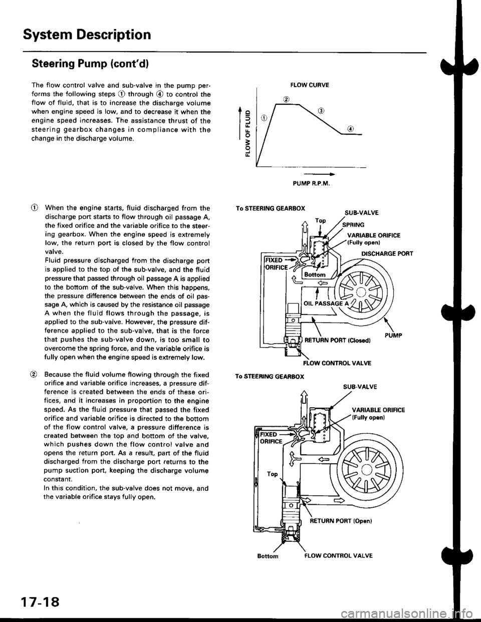
The flow control valve and sub-valve in the pump per-
forms the following steps @ through @ to control the
flow of fluid, that is to increase the discharge volume
when engine speed is low, and to decrease it when the
engine speed increases. The assistance thrust of the
steering gearbox changes in compliance with the
change in the discharge volume.
When the engine starts, fluid discharged from the
discharge port starts to flow through oil passage A,
the fixed orifice and the variable orifice to the steer-
ing gearbox. When the engine speed is extremely
low, the return port is closed by the flow control
Fluid pressure discharged from the discharge port
is applied to the top of the sub-valve, and the fluid
pressure that passed through oil passage A is applied
to the bottom of the sub-valve. When this happens,
the pressure difference between the ends of oil pas-
sage A, which is caused by the resistance oil passage
A when the fluid flows through the passage. is
applied to the sub-valve, However, the pressure dif-
ference applied to the sub-valve. that is the force
that pushes the sub-valve down, is too small to
overcome the spring force, and the variable orifice is
fully open when the engine speed is extremely low.
Because the fluid volume flowing through the fixed
orifice and variable orifice increases, a pressure dif-
terence is created between the ends of these ori-
fices, and it increases in proportion to the engine
speed. As the fluid pressure that passed the fixed
orifice and variable orifice is directed to the bottom
of the flow control valve. a pressure difference is
created between the top and bottom of the valve,
which pushes down the flow control valve and
opens the return port. As a result, pan of the fluid
discharged from the discharge port feturns to the
pump suction port, keeping the discharge volume
constant.
In this condition, the sub-valve does not move. and
the variable orifice stays fully open.
lo
trrtrrlo3
J
o
PUMP R.P.M.
To STEERING GEARBOXSUB.VALVE
To STEEnING GEARBOX
FLOW CURVE
!rs+/f/ffih\
o,,-i^"l^tKzYt)91y ul3Yl
FLOW CONTNOL VALVE
su8-vALvE
ORIFICE
ToP
17-18
FLOW CONTROL VALVE
Page 1132 of 2189

Front Suspension
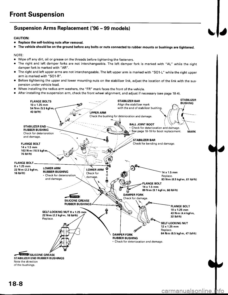
Suspension Arms Replacement ('96 - 99 models)
CAUTION:
. Replace the selt-locking nuts after removal.
. The vehicle should be on the ground betore any bolts or nuts connected to rubber mounts or bushings are tightened.
NOTE:
. Wipe off any dirt, oil or grease on the threads before tightening the fasteners.. The right and left damper forks are not interchangeable. The left damper fork is marked with "AL" while the rightdamper fork is marked with "AR'
. The right and left upper arms are not interchangeable. The left upper arm is marked with "SO1-L" while the right upperarm is marked with "SOl-R".
. Before tightening the upper and lower mounting nuts on the stabilizer link, adjust the location of the link with the sus-pension under vehicle load.
. When installing the radius arm washers, the "FR" mark faces the front ofthe vehicle.. After installing the suspension arm, ch eck the front wheel alignment, and adjust if necessary (see page 18-4).
FLANGE BOLTS10 x 1.25 mm54 N.m 15.5 kgl.m,40 tbf.ftl
STAEILIZER ENDRUBBER BUSHING
BALL JOINT BOOT. Check for deterioration and damage.. See page 18-16 for boot replacement.
STABILIZER BARCheck for bending and damage.
Check for deterioration - ---\--
and damage, -\
FLANGE BOLT14 x 1.5 mm/)l103 N.m {10.5 kg{.m,. t, ,/4,76lb{.ft) t,,"-iV
v:\FLANGE BOLT-
;iffillr-"- ilHitffi*::,"*"
and damaoe,
o.'-----------14 x 1.5 mmReplace.83 N.m {8.5 kgf.m, 61 lbf.ftl
LOWER ARMCheck for
c
JlTTda
1{ x 1.5 mm89 N.m {9.1 kgt m. 66 lbtft)
-6;SILICONE GREASERUBBER BUSHING
DAMPER FORKCheck for damage.
SELF-LOCKING NUT I x 1.2522 N.m (2.2 kg{.m, 16lbf.ftlReplace.
FLANGE BOLT10 x 1.25 mm€ N.m {4.6 kgt m.32 tbf.ft)
SELF-LOCKING NUT12x 1.25 mmReplace.6it N m {6.5 kgf.m, 47 lbf.ftl
RUEBER BUSHING. Check for deterioration and damage.
.6t",.,"o".c"KeSTAAIL|zER END RUBBER EUSHINGSNote the directionof the bushings.
18-8
Page 1133 of 2189

I
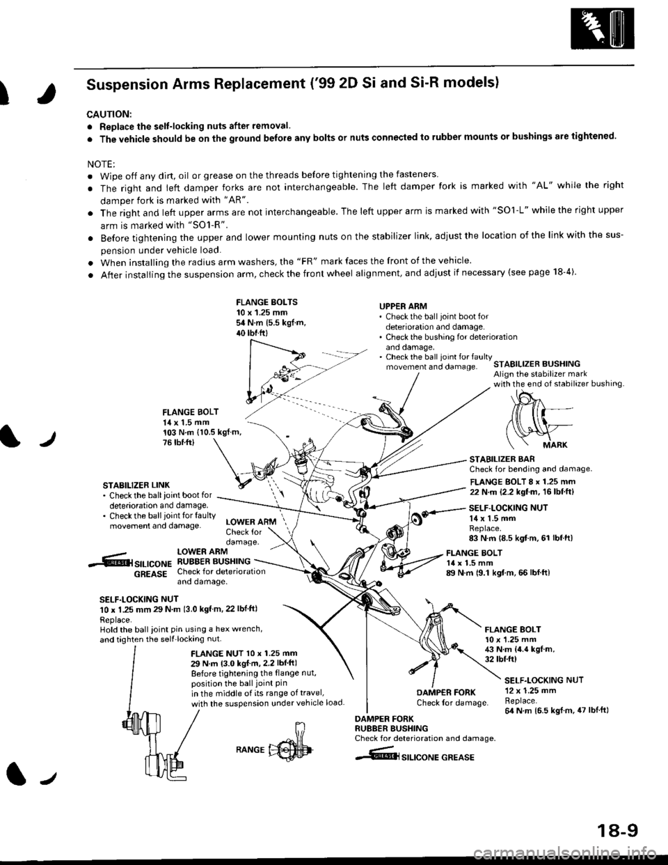
Suspension Arms Replacement ('99 2D Si and Si-R models)
CAUTION:
. Replace the selt-locking nuts after removal.
. The vehicle should be on the ground belore any bolts or nuts connected to rubber mounts or bushings are tightened.
NOTE:
. Wipe off any dirt, oil or grease on the threads before tightening the fasteners
. The right and ieft damper forks are not interchangeable. The left damper fork is marked with "AL" while the right
damper fork is marked with "AR"
. The right and left upper arms are not interchangeable. The left upper arm is marked with "SOl-L" while the right upper
arm is marked with "SO1-R".
. Before tightening the upper and lower mounting nuts on the stabilizer link, adiust the location of the link with the sus-
pension under vehicle load.
. When installing the radius arm washers, the "FR" mark faces the front of the vehicle.
. After installing the suspension arm, check the front wheel alignment, and adjust if necessary (see page 18-4).
FLANGE BOLTS10 x 1.25 mmsit N.m 15.5 kgf.m,40 tbtftl
UPPER ARM' Check the ball joint boot fordeterioration and damage.. Check the bushing for deteriorationano oamage,. Check the ball ioint fo. faultymovement and clamage.STABILIZER BUSHINGAlign the stabilizer markwith the end of stabilizer bushing
FLANGE BOLT14 x 1.5 mm
l./
103 N.m (10.5 kgf.m,76 tbr.ftl
STABILIZER LINK. Check the ballioint bootfordeterioration and damage.. Checkthe ballioint tor faultymovement and damage.
STABILIZER BARCheck for bending and damage.
FLANGE BOLT 8 x 1.25 mm22 N.m (2.2 kgf.m, 16lbf.ft)
SELF-LOCKING NUT14 x 1.5 mmReplace.83 N.m 18.5 kgf m, 61 lbf.ft)
-.6r srr-,co", hSHrtlrT.[*"u
6g619g Check for deteriorationano oamage.
SELF.LOCKING NUT10 x 1.25 mm 29 N m 13.0 kgf m, 22 lbf ftl
Replace.Hold the ball ioint pin using a hex wrench,
and taghten the self'locking nut.
LOWER ARMCheck fordamage.
FLANGE NUT l0 x 1.25 mm
29 N.m 13.0 kgI m,2.2 lbf ft)
Before tightening the {lange nut,position the ball joint Pinin the middle of its range of travel,
with the suspension under vehicle load
FLANGE BOLT14 x 1.5 mm89 N.m 19.1 kgf.m, 66 lbf.ft)
FLANGE BOLT10 x '1.25 mm43 N.m {4.4 kgf.m,32 tbtft)
DAMP€R FORKCheck lor damage.
DAMPER FORKRU88ER BUSHINGCheck for deterioration and damage.
4@lsrlrcoNE GREASE
SELF.LOCKING NUT12 x 1.25 mmReplace.64 N m 16.5 kgl.m, 47 lblft)
J
RANGE
18-9
Page 1202 of 2189
L
Wheel Soeed and Modulator Contlo
t
OUTLETVALVE ON
OFF
INLETVALVE ON
OFF
t\,40ToR
ON
OFF
when the wheel speed drops sharply below the vehicle speed, the inlet valve closes to retain the caliper fluid pressure
When the wheel speed drops further, the outlet valve opens momentarily to reduce the caliper fluid pressure. The pump
motor starts at this time.
As the wheel speed is restored, the inlet valve opens momentarily to increase the caliper fluid pressure.
Wheel SensoJ
The wheel sensors are the magnetic contactless type
As the gear pulser teeth rotate past the wheel sensor's magnetic coil, AC current is generated The AC frequency changes
in accordance with the wheel speed. The ABS control unit detects the wheel sensor signal frequency and thereby detects
the wheel speed.
There are four wheel sensors, one for each wheel
The gear pulser has 50 teeth.
EEL SPEED
at LOW SPEEDgl
=o
GEAR PULSEBWHEEL SENSOBat HIGH SPEED
/
19-49
Page 1364 of 2189
Body ('99 model)
Dashboard
Center Panel Removal and
lnstallation
Bumpers
Front Grille Removal and
lnstallation
Front Air Spoiler Replacement ."'.....
Seats
Front Seat DisassemblY and
ReassemblY 20-138
Front Seat Torsion Bar
Replacement '.'...".'....'... 20-139
Emblems
tnstallation 20-140
20-136
20-136
20-137
Outline of '99 Model Changes
The center Danel removal and installation procedures are different'
The front grille removal and installation procedures are different'
The front air spoiler has been added for some models of 2D'
A height-adjustable driver's seat was added to some models'
Emblems were added for some models ot 2D'