1997 HONDA CIVIC Hydraulic system
[x] Cancel search: Hydraulic systemPage 887 of 2189

Secondary Valve Body
The secondary valve body contains the PH regulator valve. the clutch reducing valve' the start clutch valve accumulator'
and the shift inhibitor valve
PH Regulator Valve
The pi regulator valve maintains hydraulic pressure supplied from the ATF pump. and supplies PH pressure to the
hvdraulic control circuit and the lubrication circuit. PH pressure is regulated at the PH regulator valve by the PH control
pressure (PHC) from the PH control valve.
Cluteh Reducing Valvo
The clutch reducing valve receives PH pressure from the PH regulator valve and regulates the clutch reducing pressure
(cR). The clutch reducing valve supplies clutch pressure (cR) to the manual valve and the start clutch control valve' and
supplies signal pressure to the PH-PL pressure control valve. the shift control valve, and the inhibitor solenoid valve'
Start Clutch Valv€ Accumulator
The start clutch vatve accumutator stabilizes the hydraulic pressure that is supplied to the start clutch'
Shift Inhibitor Valve
The shift inhibitor valve switches the fluid passage to switch the start clutch control from electronic control to hydraulic
control when the electronic control system is faulty. lt also suppliss clutch reducing pressure (cR) to the pitot regulator
valve and the pitot lubrication pipe.
START CLUTCH VALVE
SECONDARY VALVEBODY
SHIFT INHIBITOE VALVE
(cont'd)
PH REGULATOR VAL
REDUCING VALVE
14-209
Page 898 of 2189

Description
Hydraulic Flow (cont'd)
lll position, when th€ electronic control system is fauhy.
when the electronic control svstem (linear solenoids and sensors) is faulty, the transmission uses the pitot pipe pressure(PP) to 311o- rh" u"hicle to drive.
when all linear solenoids and sensors are off because of a faulty electronrc control system, clutch reducing pressure (cR)flows to the start clutch control valve, the manual valve, the PH-PL control valve, and the shift control valve. clutch reduc-ing pressure (cR) becomes shift varve pressure (sV) at the shift contror varve, and shift varve pressure {sv) is appried tothe left end of the shift valve and the right end of the shift inhibitor valve. The shift valve moves to the right side. anduncovers the pon that leads high pressure (PH) to the drive pulley and uncovers the po.t tlr"t r""1" ro,,"-pressure (pL) tothe driven pulley At this time, the pulley ratio is high, The shift inhibitor valve moves to the left side, and uncovers theport that leads shift inhibitor pressure (Sll to the pitot lubrication pipe and the pitot regulator valve. tne prtot lubricationpipe discharges fluid inside of the pitot flange, and discharged fluid enters into the pitot pipe and it is applied to the leftend of the pitot regulator valve. The pitot regulator valve moves lo the right side, and uncovers the port that leads pitotregulator pressure (PR) to the shift inhibitor valve. Pitot regulator pressure {pR) becomes start clutch pressure {sc1 at theshift inhibitor valve, and is applied to the stan clutch. The stan clutch rs engaged. The forward clutch pressure (FWD) isapplied to the forward crutch, and the forward crutch is engaged. This alows the vehicre to drive.
NOTE: When used. "|eft" or ,,right', indicates direction on the hydraulic circuit.
14-220
I.
Page 899 of 2189
![HONDA CIVIC 1997 6.G Workshop Manual E] position, when the elestronic Gontrol system is faulty
The flow of tluid up to the drive pulley, the driven pulley and the start clutch is the same as in El position
The manual valve is shifted i HONDA CIVIC 1997 6.G Workshop Manual E] position, when the elestronic Gontrol system is faulty
The flow of tluid up to the drive pulley, the driven pulley and the start clutch is the same as in El position
The manual valve is shifted i](/manual-img/13/6068/w960_6068-898.png)
E] position, when the elestronic Gontrol system is faulty'
The flow of tluid up to the drive pulley, the driven pulley' and the start clutch is the same as in El position
The manual valve is shifted into the lE position' and it uncovers the port that leads reverse brake pressure {RVS} to the
reverse inhibitor valve. Reverse ,"nlu-i,"ip*r""i" (Rl) is applied to.the right end of the reverse inhibitor valve because of
afaultyinhibitorsolenoid.The'"t'",""inftiUito'valvemovestotheleftside'anduncoverstheportthatleadsreverse
brake pressure {RVS) to the ,"u"r." ir"t"- cru,ch reducing pressure (cR) becomes reverse brake pressure (RVS) at the
manual valve, and,lows to the ,e
"rs" lr"re. ttre reverse brake is engaged and locks the ring gear' This allows the vehi-
cle to drive in reverse.
NOTE: When used, "left" or "right" indicates direction on the hydraulic circuit'
14-221
Page 971 of 2189

Symptom-to-Component Chart
Hydraulic System
*1: Some gear noise is normal in the Lll position due to planetary gear action.
14-294
SYMPTOMCheck these items on the PBOBABLE CAUSE List
Engine runs, but vehicle does not move in any position.'t,2,3,4,5,6,7,8,9, 10, 20, 34, 35, 36, 38, 41
Vehicle does not move in @, [. p positions.10,11, 12, 20, 41
Vehicle does not move in E position.5, 'to, 11, 12, 17, 1A, 19, 20,39, 41
No shift to higher ratio,9, 13, 14. 15, 16,35,37,40
Poor acceleration.9, 13,'�t4,'t5,16. 20, 35, 37, 38, 40
Flares on moving.9,'t0, 20, 2't, 35, 36, 38, 40, 42
Excessive shock when depressing and releasing.^^alA/.r^r ^A.1. I9, 10, 20, 2'1, 35, 36, 3A, 42
No engine braking.9,20,21,35,36,38
Vehicle does not accelerate in lll position.9, 17, 18, 19, 20. 35, 36, 38
Vehicle moves in E position.
(Shift cable adjustment is proper).10, 22,23
Late shift from N position to E position, and from Eposition to E position.'10,11, 12,22, 41
Late shift from E position to E position. and from Eposition to N position.1l,'t2, 17, 18,22, 41
Engine stops when shifted to E position from E position.9, 10,20,35,37,34, 42
Engine stops when shifted to E position from I position.9, 18, 19,20,25,26,35,37,38, 42
Noise from transmission in @ position.rl5, 17, 18, 't9,25,26
Excessive idle vibration.2,3,4,21,24
Noise from transmission in @ and @ positions.2,3, 19,24,25,2A
Hunting engine speed.16, 35, 37, 38
Vibration in all position.8, 2a
Shift lever does not operate smoothly.11,29, 4'l
Transmission will not shift into lll position or transmis-
sion cannot be removed from E position.11 , 29, 30, 31, 32,33
Vehicle does not accelerate to more than a certain speed.9, 10, 14, 15,'t6,20,35,37
Excessive shock on starting off.38, 42
Flares on accelerating at low speed.20, 21 ,38, 42
Excessive vibration in E, E, tr, E positions.20,21,38, 42
Low engine speed in E. E. tr. E positions.20,21,38,42
Stall speed high.10,20,38
Stall speed low.9, 20, 27 ,37 , 38
Judder on starting off.20, 43
Page 1072 of 2189

System Description
Fluid Flow Diagram
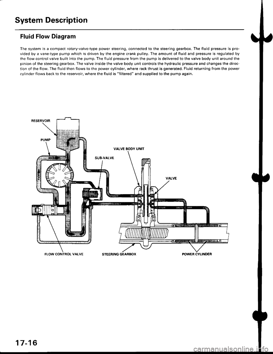
The system is a compact rotary-valve-type power steering, connected to the steering gearbox. The fluid pressure is pro-
vided by a vane-type pump which is driven by the engine crank pulley. The amount of fluid and pressure is regulated by
the flow control valve built into the pump. The fluid pressure from the pump is delivered to the valve body unit around the
pinion of the steering gearbox. The valve inside the valve body unit controls the hydraulic pressure and changes the direc-
tion of the flow. The fluid then flows to the power cylinder. where rack thrust is generated. Fluid returning from the power
cylinder flows back to the reservoir, where the fluid is "filtered" and supplied to the pump again.
RESERVOIR
VALVE BOOY UNIT
SUB.VALVE
FLOW CONTROL VALVESTEERING GEARBOX
17-16
Page 1076 of 2189

System Description
Steering Gearbox
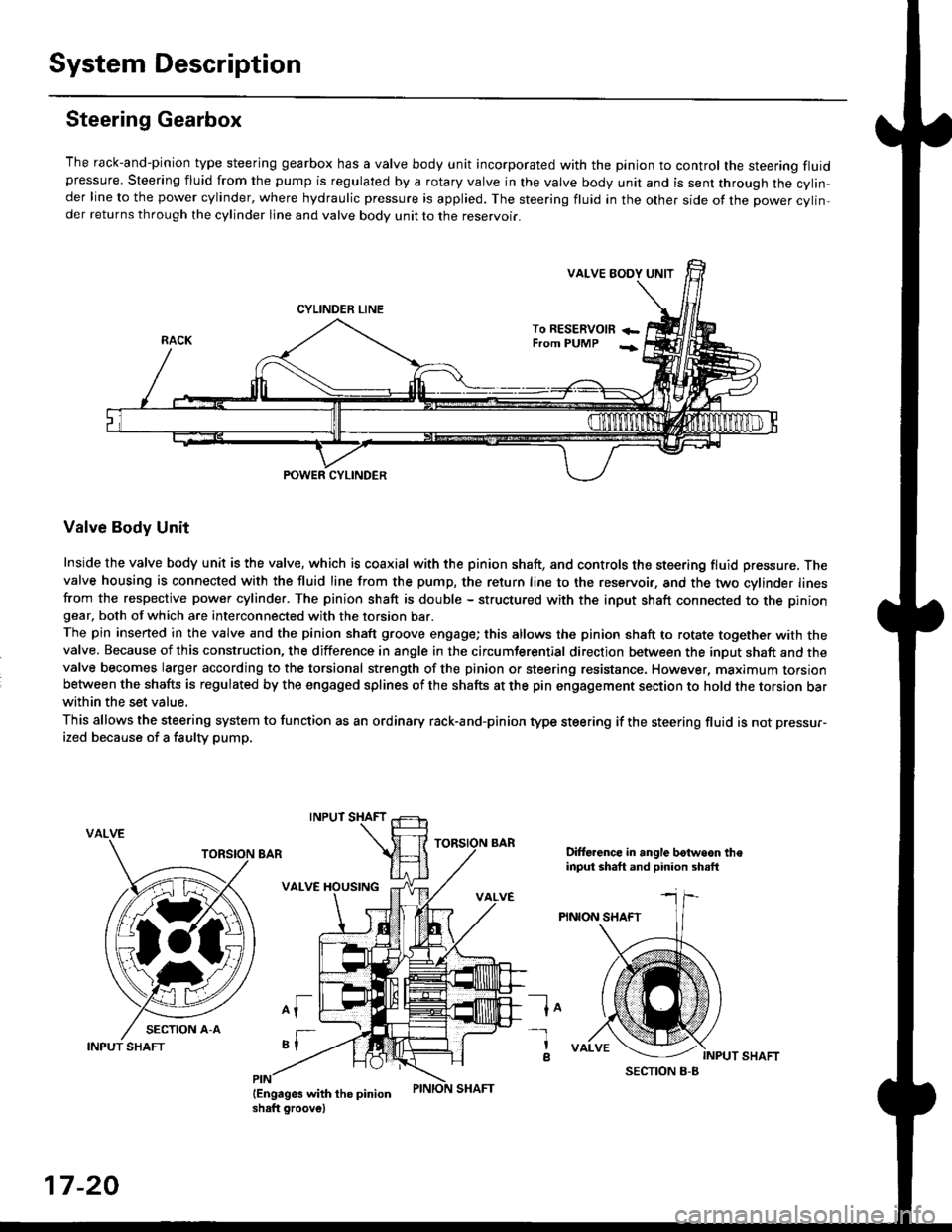
The rack-and-pinion type steering gearbox has a valve body unit incorporated with the pinion to control the steering fluidpressure. Steering fluid from the pump is regulated by a rotary valve in the valve body unit and is sent through the cylin,der line to the power cylinder, where hydraulic pressure is applied. The steering fluid in the other side of the power cylin,der returns through the cylinder line and valve body unit to the reservoii.
VALVE EODY UNIT
CYLINDER LINE
To RESERVOm +-From PUMP -;
POWER CYLINDER
Valve Body Unit
Inside the valve body unit is the valve, which is coaxial with the pinion shaft, and controls the steering fluid pressure. Thevalve housing is connected with the fluid line from the pump, the return line to the reservoir, and the two cylinder linesfrom the respective power cylinder. The pinion shaft is double - structured with the input shaft connected to the piniongear, both of which are interconnected with the torsion bar.
The pin inserted in the valve and the pinion shaft groove engage; this allows the pinion shaft to rotate together with thevalve. Because of this construction, the difference in angle in the circumferential direction between the input shaft and thevalve becomes larger according to the torsional strength of the pinion or steering resistance. However, maximum torsionbetween the shafts is regulated by the engaged splines of the shafts at the pin engagement section to hold the torsion barwithin the set value,
This allows the steering system to function as an ordinary rack-and-pinion type steering if the steering fluid is not pressur-
ized because of a faulty pump,
VALVE
Difforence in angle botwoon theinput shaft and pinion shsft
PINION SHAFT
lo
INPUT SHAFT
-l
a
17-20
INPUT SHAFT
Page 1201 of 2189

Anti-lock Brake System {ABS)
Operation (cont'dl
ABS Modulator
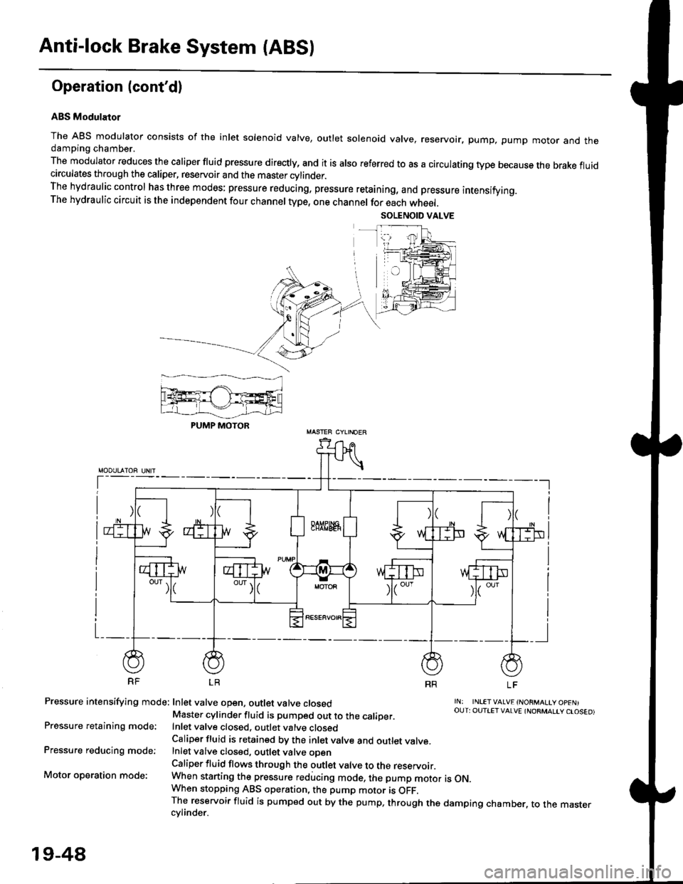
The ABS modulator consists of the inlet solenoid valve, outlet solenoid valve, reservoir, pump, pump motor and thedamping chamber.
The modulator reduces the caliper fluid pressure directly, and it is also referred to as a circulating type because the brake fluidcirculates through the caliper, reservoir and the master cylinder.The hydraulic control has three modes: pressure reducing, pressure retaining, and pressure intensifying.The hydraulic circuit is the independent four channel type, one channel for each wheel.
RF LR
Pressure intensifying mode: Inlet valve open, outlet valve closed
Pressure retaining mode:
Pressure reducing mode:
Motor operation mode:
rN: INLETVALVE {NORMALtY OpENIOUT: OUTIET VALVE {NORMALIY CTOSED)Master cylinder fluid is pumped out to the caliDer.Inlet valve closed, outlet valve closedCaliper fluid is retained by the inlet valve and outlet valve.Inlet valve closed, outlet valve oDenCaliper fluid flows through the outlet valve to the reservoir.When starting the pressure reducing mode, the pump motor is ON.When stopping ABS operation, the pump motor is OFF.The reservoir fluid is pumped out by the pump, through the damping chamber, to the mastercvlinder.
PUMP MOTOR
19-48
Page 1945 of 2189

- How the Circuit Works
The anti-lock brake system (ABS) prevents locking
of the wheels as a result of heavy braking and/or
poor lraction. A vehicle with locked wheels cannot
be steered. The anti-lock brake system controls the
application of the brakes, allowing the driver to
maintain control of the steering.
Under anti-lock conditions, the antilock brake
system (ABS) modulates the pressure of the brake
tluid to each brake caliper. This system is a four
channel system: the pressure at each caliper is
controlled independently of the pressure al any
other caliper. Whenever a wheel is likely to lock
dunng braking, the anti-lock brake system
modulates the brake oressure at that wheel. When
the brake pressure is reduced to the point where
there is no longer any possibility of wheel locking,
the system returns to the conventional braking
system mode of operation.
Battery voltage is applied at all times through fuse
63 to the ABS control unit. When the ignition switch
is in ON (ll), battery voltage is supplied to the
control unit through fuse 16. The control unit is case
grounded. Inputs are received from the brake switch
and the individual wheel sensors located at each
wheel. The ABS control unit uses these inputs to
control the modulator solenoid unit. The solenoids
adjust the hydraulic pressure applied to each
calioer.
The ABS control unit has a self-diagnosis function.
When the control unit detects a fault, it turns on the"ABS" indicator and disables the anti-lock brake
system. lf the fault is not in the conventional braking
system, the brakes will continue to operate normally
but without the anti-lock feature.
Refer to the Service Manual (Section '19,
Anti-Lock Brake System) for specific tests or
troubleshooting procedures.
44-3