1997 HONDA CIVIC Fuel pump control
[x] Cancel search: Fuel pump controlPage 361 of 2189

Troubleshooting
Engine/P_o,wertrain Control Module Terminal Arrangement('99 - 00 Models except Dl6Y5 engine with M/Tl
ECM/PCM CONNECTOR A (32P)Wire side ot temale terminalsNOTE:Standard battery voltage is l2 V
ECM/PCM CONNECTOR A I32PI
Sign!l
3BLU2WSS (EVAP 8YPAsS SOLENOIDDrives EVAP bypass solenoid vatve,With gn'tion swnch ON (lll banery votlage
LT GRN/I/VIITVSV {EVAP CONTNOL CANISTERVENTSHUTVALVE]Drives EVAP controt ca n isrer v€nt shutWilh ignilion switch ON {tl): b€ttery vottage
8LU/GNNC8S (CRUISE CONTSOL SIGOown shift signal inpot lrom c.uise conrrolWhen crurss control is used:purses
68ED/YELPCS {EVAP PURGE CONTROLSOTENOIOVALVE)Drives EVAP purge conrrol sotenoid vatve.With engine running, engine cootant, betow r54.F (6a,C):
With engine.unning, €ngine coolant, abov€ 154.F(68'C): duty conlrolled
YELATPD {AT GEAR POSITIONSWITCH)ootects A/T gear posnion swilch s,gnar.In otherthan @ posilion: Apprcx. 5 V
8BLK,IflHTSO2SHTC (SECONDARY HEATED OXYGEN SENSOS HEATEFCONTFOL)
Drives sscondary h€ared oxygen senso.Wilh isn,rion swirch ON (ll):banery votraseWith lully warm6d dp€ngire runn'ng:dury controled
LT GRNATPNP (AT GEAF POSITIONSWITCH)oereds A/T 9€a r position switch signat.In Parr or neulrsl:0 VIn anyother position approx.5 v
t088NSCS (SERVICE CHECK SIGNAL)Oetects ssruice check connecror signal(the signalcausing a OTC indication)with rh€ t6rminal connected: 0 vWith the rerm ina I disconneded: abour 5 V of ban€ry
GNN/BIKD4IND (D4INDICATON]Drives Oa indicaio. lighr.With D4 indicator lightturned ON: O VWith D4 indicator lightturned OFF: battery vo ttageG8N/YETFTF (FUEL PUI\,4P SELAY)Orivos tuel pump relay,0V for two s€conds lfrer turnrng rgnilior swtcn ON(ll), then batt€ry voltage11BTI(REDACC (Al/C CTUTCH SELAY)Drives A./C clutch reray.With compressor ON:O VWilh comp.ssor OFF; battery vottage18GFN/OFNMI! (A,IAIFUNCTION INDICA.TOF LIGHT)With MlLturned ON:0 VWith l\,llL tornod OFF|batrery votrsge198tuNEP (ENGINE SPEED PUTSEIOulputs6ngine speed pulse,Wilh engin6.unning: putses
20GFNFANC {SADIATOR FAN CONTnoL)Orives radiarortan relay.Wirh r.distor t6n running:OVWith radiatortan stopped: banery vottage21ELUA/ELK LINESends and r€ceives s.an lool signal.With ignition switch ON (ll):p!ts€s
22'lBLUATP L {AT GEAS POSITIONswtTcH)Oelocis A"/T gear posirion switch siSnat.In othfflhan E position: Apprcx. 5 V
23SHO25 (SECONOARY HEATEDOXYCEN SENSOR, SENSOF 2)Detects secondsry hoar€d oxygen sensorWith lhronle f! lly or'6ned from idte with fu ywarmod up engine: above 0.6 vWiih th.onl6 quickb, closd:below 0,4 V24STS ISTAFTEN SWITCH SIGDebcrs staner switch signat.Wirh srarterswitch ON (tttJ: batteryvottogeWith sraftsr cwirch OFF:0 V26GFNPSPSW iPlS PNESSURESWITCII SIGNAL)Derecrs PSP switch signat.Atidle with steoring wheolin srraightahead position: O VAt idl6with steering wheetal fult lock: barery vo ttags27BLU/REOACS (AJC SWITCH SIGNALJOer*ts ,ay'C swirch signat.Wiih ty'C switch ON;0VWilh Ay'C switch OFF|aboor 5VWHT/REDSLU iINTERLOCK CONTROIUNIT)Drivos interloct control unit.With ignltion switch ON (ll)and brake pedaldepresed: batlory volrage29LT GRNPTANK (FUEL TANK PFESSUEESENSOR)Oer6ds lu€l tank pr€ssura sonsor signat.Wilh ig.rrrd swirch ON rttr and fuetti
cap ooen6d.
30GRN/FEOEr (ELOIWith parking lighlsrurned on ar idteiaboui 2.5- 3.S VWirh low beam he€dlig hts turnqd on ai idts: aboul 1.52.5 V32GRN/'WHTAKSW (BFAKE SWITCH)Detets brak€ swrtch signEt,With brake pedal r6l€ased:0 VWhh brake pedaldepres*d: battery voltEse'1:A./T (D16Y7, D16Y8 engine)*2: rvt/T13: CVT (D16Y5 engine)
11-92
Page 373 of 2189

PGM-FI System
System Description
CKP/TDC/CYP Sensor
MAP Sensor
IAT SensorTP SensorEGR Valve Lift Sensor*'Primary H02SSecondary HO2SVSSBARO SensorELD*'KS€Starter SignalALT FR SignalAir Conditioning SignalA/T Gear Position SignalBattery Voltage {lGN.1}Erake Switch SignalPSP Switch SignalFuel Tank Pressure Sensor*iVTEC Pressure Switch*5Clutch Switch Signal*6Countershaft Speed SensornBMainshaft Speed Sensorrs
-\
----t /
F;ilrr j"-----fi-tri-'r.;l
Fb"t."'i" d" c;;il
F,h"'c;;tr*".io";-l
@."r.l"sc;;ll
EaM/PcM B""k-p F"""till
r\
-:/
Fuel IniectorsPGM-Fl Main Belay {Fuel Pump)MILIAC Valve!y'C Compressor Clutch RelayRadiator Fan Relay*,Condenser Fan RelayALT*'lcMEVAP Purge Control Solenoid
Primary HO2S HeaterSecondary H02S HeaterEGR Control Solenoid Valve*rEGR valve*6EVAP Bypass Solenoid Valve*'EVAP Control Canister Vent Shut
VTEC Solenoid Valve*5DLCLock-up Control Solenoid Valve*aShift Control Solenoid Valve*3Linear Solenoid Valve*3
*1: Dl6Y5 engine*2: USA model*3: CW (D16Y5 ensine), D16Y8 engine and 81642 ensine*4: '96 D16Y8 engine lcoupe),'97 Dl6Y7 engine (coupe: KL model, sedan: KL (LX) model),'97 D16Y8 engine {coupe: all models, sedan: KLmodel),'98-all models,'99'all models,'00-all models+5: D16Y5, D16Y8,816A2 engine*6: M/T (D16Y5 enginei*7: CVT 1D'l6Y5 engine)+8: A/T (D16Y7, D16Y8 engine)*9: '96 D16Y5 engine,'96 D16Y7 engine,'96 Dl6Y8 engine (sedan),'97 D16Y5 engine,'97 Dl6Y7 engine (coupe: KA, KC models, sedan:KA, KC, KL (LX) models, hatchback: all models),'97 D16Y8 engine (sedan: KA, KC modelsi
PGM-FI Sy3lem
The PGM-Fl system on this model is a sequential multipon fuel injection system.
Fuel iniector Timing and Duration
The ECM/PCM contains memories for the basic discharge durations at various engine speeds and manifold air flow rates.
The basic discharge duration, after being read out from the memory. is further modified by signals sent from various sen-
sors to obtain the final discharge duration.
ldle Air Control
ldle Air Control Valve llAC Valve)
When the engine is cold. the A,/C compressor is on, the transmission is in gear, the brake pedal is depressed, the P/S load
is high, or the alternator is charging, the ECM/PCM controls current to the IAC Valve to maintain the correct idle speed.
lgnition Timing Control
. The ECM/PCM contains memories for basic ignition timing at various engine speeds and manifold air flow rates.
lgnition timing is also adjusted for engine coolant temperature.
. Aknockcontrol system was adopted which sets the ideal ignition timing for the octane rating ofthegasoline used.*3
Othgr Control Funqtions
1. Starting Control
When the engine is started, the ECM/PCM provides a rich mixture by increasing fuel injector duration.
2. Fuel Pump Control
. When the ignition switch is initially turned on, the ECM/PCM supplies ground to the PGM-Fl main relay that sup-plies current to the fuel pump for two seconds to pressurize the fuel system.. When the engine is running, the ECI\4PCM supplies ground to the PGM-FI majn relay that supplies current to the fuel
oumo.
. When the engine is not running and the ignition is on, the ECM/PCM cuts ground to the PGM-FI main relay which
cuts current to the fuel pump.
11-104
INPUTS
ENGINE CONTROL MODULE (ECMY
POWERTRAIN CONTROL MODULE (PCM) OUTPUTS
Page 377 of 2189

PGM-FI System
Engine Control Module/Powertrain Control Module (ECM/PCMI
('96 - 98 Models,'99 - 00 Dl6Y5 engine with M/Tl (cont'd)
NOTE:. When there is oo Diagnostic Trouble Code (DTC) stored, the MtL wi
stay on if the SCSservace connector is connected and the ignition switch is on,. lf this symptom is intermittent, checklor:- A loose Fl E/M 115 A) fuse in the under hood luse/relay box- A loose No. 13 FUEL PUMP fuse (15 A) in the underdash fuse/relay box- An intermittent shon in the wire between the ECM/PCM (C7) and the service cnecKconnector- An intermittent short in the wire between the ECM/PCM (A18) and the gaugeassembly- An intermittent shon in the wire between the ECM/PCM {D4) and the MAp sensorAn intermittent short in the wire between the ECM/PCM (D10), the Tp sensor, theEGR valve l:ft sensor (D16Y5 engine) and/or the Fuel tank pressure sensor (,96Dl6Y8 engine (coupe), '97 016Y7 engine (coupe: KL model, sedan: KL (LX) modeli,'97 016Y8 engine {coupe: all models, sedan: KL modeti,'98,all models}- PGM-FImain relay. See the OBD ll scan tool or Honda PGM Tester user's manuals lor specitic operatinginstructions.
ECM/PCM CONNECTOR C 13lPI
Wire side of female terminals
(To page 11 109)
(To page 11,109)
11-108
The Maltunction Indicator Lamp(MlLl stays on o. comes on eftartwo s€conds,
Check the Oiagnoslic TroubleCode {DTC}I1. Connect a scan tool or HondaPGM Tester.2. Turn the ignition switch ON (ll).
3. Read the DTC with the scantool or Honda PGM Tester.
Go to troubleshooting p.oc€dur€s(se€ pago 11{11.Are any DTC{s) indicated?
Check the DTC by MIL indication:1. Turn the ignition switch OFF.2. Connect the SCS service con,nector to the service checkconnector.3. Turn the ignition switch ON (lli.
Repair opon ol short in wirebotwoen the ECM/PCM (C8)
and Data Link Connector.Go to troublelhooting proce-dure ls6e page 11-811.
Does the MIL indicate any DTC?
Try to start the engine.
Does the engine start?
Check for a short in the wire(SCS lin€l:1. Disconnect the SCS serviceconnector.2. Stop the engine and turn theignition switch ON {lli.3. Measure voltage between theECM/PCM connector terminalC7 and body ground.
Ropair short to body Iround inthe wire betweon ECM/PCM lCTland sorvice check connector.
ls there approx. 5 V?
scs tBRNI
Page 380 of 2189
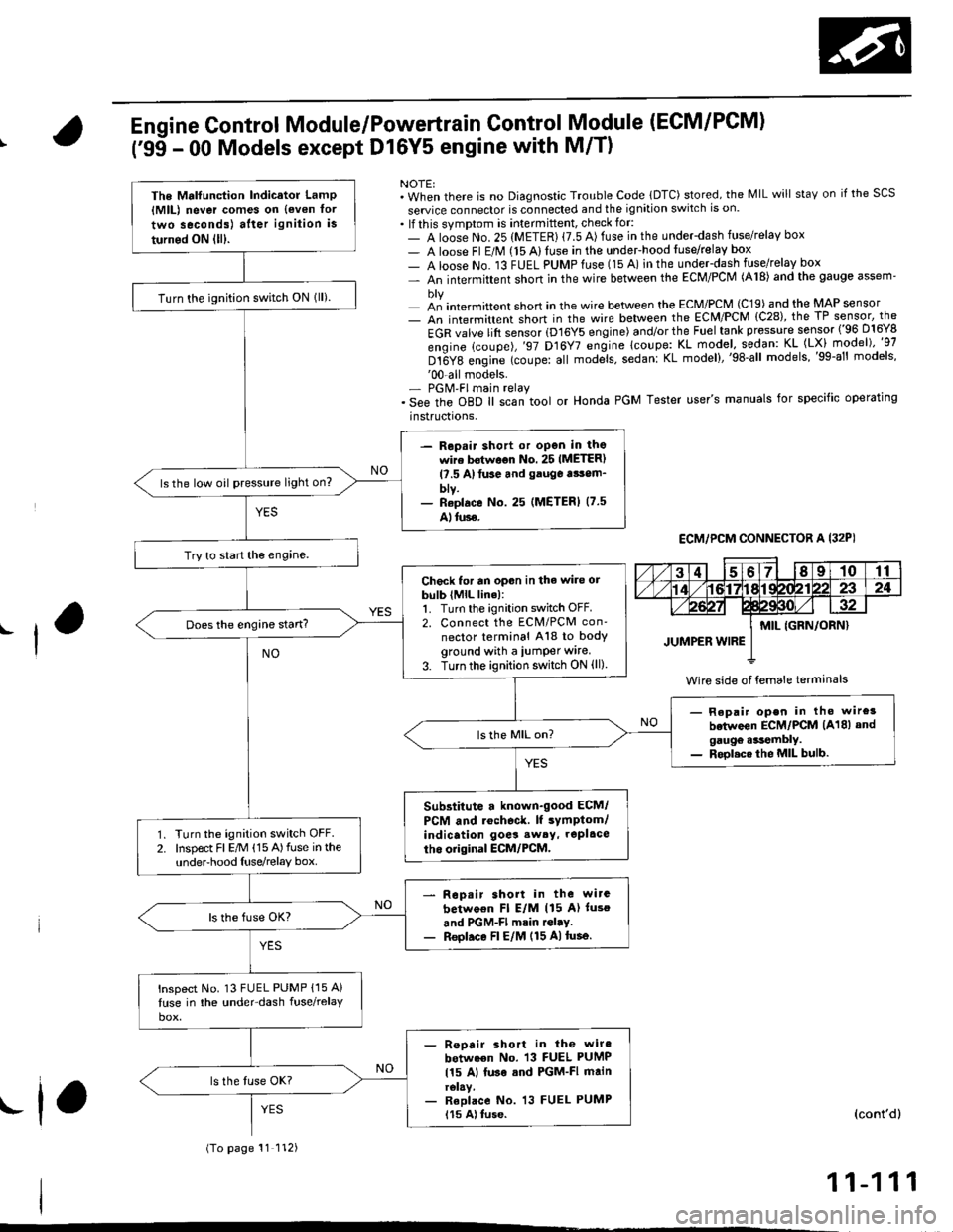
Engine Control Module/Powertrain Control Module (ECM/PCM)
('95 - 00 Models except Dl6Y5 engine with M/T)
NOTE:. When there is no Diagnostic Trouble Code lDTC) stored, the MIL will staY on if the SCS
seruice connector is connected and the ignition switch is on.. lf this symptom is intermittent, check for:- A loose No. 25 (METER) {7.5 A) fuse in the underdash fuse/relay box- A loose Fl E/M (15 Alluse in the undeFhood fuse/relay box- A loose No. 13 FUEL PUMPfuse (15 A) in the under-dash fuse/relay box- An intermittent shon in the wire between the ECM/PCM (A18) and the gauge assem'
- an intermittent short in the wire between the ECM/PCM (C19) and the MAP sensor- An intermittent short in the wire between the ECM/PCM {C28), the TP sensor, the
EGR valve lift sensor (D16Y5 engine) and/or the Fuel tank pressure sensor ('96 D16Y8
engine (coupe),'97 D16Y7 engine lcoupe: KL model, sodan: KL (LX) model)"g7
Dt6Y8 engine (coupe: all mod;ls, sedanl KL model),'98-all models,'99-al' models''00-all models.- PGM'FI main relay. See the oBD ll scan tool or Honda PGM Tester user's manuals for specific operating
instructrons,
ECM,/PCM CONNECTOR A I32PI
Wire side of {emale terminals
The Mrlfunction Indicator LamP{MlL) never comes on {even tor
two seconds) after ignition is
turned ON lll).
Turn the ignition switch ON lll).
- Repair shott or open in thowire bstwoon No. 25 IMETER)l?.5 A)tuse and gauga tsom_blv.- Reolace No. 25 (METERI (7.5
Alluse.
ls the low oil pressure light on?
Try to start the engine.
Check for an opon in the wire orbulb (MlL line):1. Turn the ignition switch OFF.2. Connect the ECM/PCM con'
nector terminal A18 to bodyground with a iumper wire.
3. Turn the ignition switch ON (ll)
Does the engine start?
- Repair open in tho wire3
betwoon ECM/PCM (A18) andgaugo .*tembly.- Rool.ce the MIL bulb.
Substitute a known-good ECM/
PCM and rochoc&. lf sYmptom/indication goes sw6y, repl.ce
tho original ECM/PCM.Turn the ignition switch OFF.Inspect Fl E/M (15 A)fuse in theunderhood Iuse/relay box.
Rop.ir short in the wirc
betwo€n Fl E/M (15 A) luso
and PGM-Fl mrin rGl.y.Reol.ce Fl E/M (15 A)tusa.
lnspect No. 13 FUEL PUMP {15 A}
luse in the under-dash fuse/relay
- Reoair short in the wiro
between No. 13 FUEL PUMP
115 Al luse sod PGM-FI mainrelay.- Reolace No. 13 FUEL PUMP115 A) tuse.
(To page 11 112)
(cont'd)
11-111
.f,
Page 433 of 2189
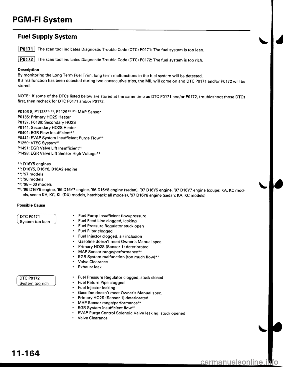
PGM-FI System
Fuel Supply System
D017-il Th""""ntool indicates Diagnostic Troubte Code {DTC) p0171;Thefuet system istoo lean.
1P0172 | fne scan tool indicates Dlagnostic Trouble Code (DTC) P0172:Thefuel system istoo rich.
Description
By monitoring the Long Term Fuel Trim, long term malfunctions in the fuel system will be detected.lf a malfunction has been detected during two consecutive trips, the MIL will come on and DTC P0171 and/or P0172 will bestored.
NOTE: lf some of the DTCS listed below are stored at the same time as DTC P0171 andlot P0172, ltouhleshoot those DTCSfirst. then recheck for DTC P0l7l andlot P0172.
P0106-8, P1128*3. *5, P1129*3 *5 MAP Sensor
P0135; Primary HO2S Heater
P0137. P0138: Secondary HO2S
P0'141: Secondary HO2S Heater
P0401: EGR Flow Insufficient*1
P0441: EVAP System Insufficient Purge Flow*6
P1259: VTEC System*,
P1491:EGR Valve Lift Insufficient*r
P1498: EGR Valve Lift Sensor Hjgh Voltage*r
*r: D16Y5 engines*'�: Dl6Y5, D16Y8, 81642 engine*3: '97 models*a:'96 modelsf 5: '98 - 00 models*6: '96 D16Y5 engine,'96 D16Y7 engine,'96 D16Y8 engine (sedan),'97 D16y5 engine,,97 D16y7 engine (coupe: KA, KC mo+els, sedan KA. KC, KL (DX) models. hatchback; all models),'97 D16Y8 engine (sedan: KA, KC models)
Possible Cause
DTC P0'171
loo lean
DTC P0172
too rach
Fuel Pump insuff icient f lovpressure
Fuel Feed Line clogged, leaking
Fuel Pressure Regulator stuck open
Fuel Filter clogged
Fuel Injector clogged, air inclusion
Gasoline doesn't meet Owner's Manual spec.
Primary HO2S (Sensor 1) deteriorated
MAP Sensor range/performance*.
EGR System malfunction (too much flow)*1
Valve Clearance
Exhaust leak
Fuel Pressure Regulator clogged, stuck closed
Fuel Return Pipe clogged
Fuel Injector leaking
Gasoline doesn't meet Owner's Manual spec.Primary HO2S (Sensor 1) deteriorated
MAP Sensor range/performance*a
EGR System insufficient flow*1
EVAP Purge Control Solenoid Valve leaking, stuck opened
Valve Clearance
11-164
Page 434 of 2189
t
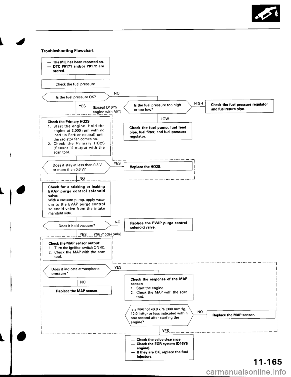
Troubleshooting Flowchart
'l
NO
a-,-:- -
YES
- The MIL ha3 b€on rePorled on.- DTC P0171 a^dlot P0172 arc
stored,
is the fuel pressure OK?
Check the fuel pt€ssure regulator
and fusl re{urn pipe.ls the fuel pressure too high
ortoo low?
Check the Primary HO2S:
1. Start the engine. Hold the
engine at 3,000 rpm with no
Ioad (in Park or neutral) until
the radiator Ian comes on
2. Check the Primary HO2S(Sensor 1) output with the
scan tool,
Check the tu6l pump. fuel leedpipe, fu€l fiher, and Iuel Pressureregulator.
Does it stay at less than 0.3 V
or more than 0.6 V?
Check lor a sticking or leaking
EVAP purge control solenoid
With a vacuum PumP, aPPIY vacu-
um to the EVAP purge control
solenoid valve from the intake
manifold side.
Does it hold vacuum?
Check the MAP sensor outputr
1. Turn the ignition switch ON (ll)
2. Check the MAP with the scan
tool.
Check th6 response of the MAP
sensoa:1. Start the engine.2. Check the MAP with the scan
tool.
ls a MAP of 40.0 kPa 1300 mmHg,12.0 inHg) or less indicated within
one second after starting the
engine?
- Check th€ valve cloarance.- Check the EGR rystem lD16Y5enginel.- lf they are OK, r€place the tueliniocto]3.
1 1-165
Page 435 of 2189
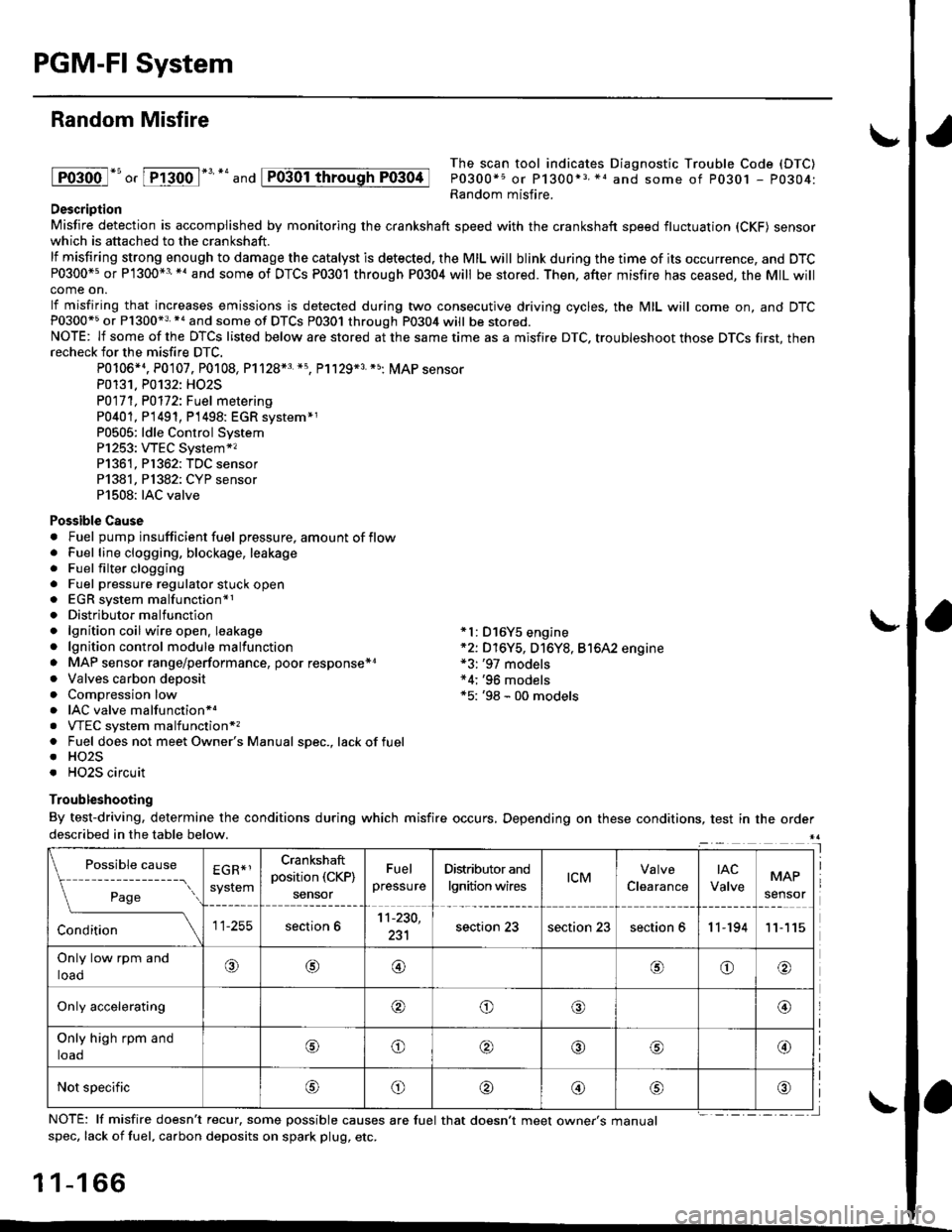
PGM-FI System
Random Misfire
lFoioo l*u o, [FTioo l*' *' and
The scan tool indicates Diagnostic Trouble Code (DTC)
P0300*5 or P1300*3 *1 and some of P0301 - P0304:Random misfire.Description
Misfire detection is accomplished by monitoring the crankshaft speed with the crankshaft speed fluctuation (CKF) sensorwhich is attached to the crankshaft.
lf misfiring strong enough to damage the catalyst is detected. the MIL will blink during the time of its occurrence, and DTCP0300*5 or P1300*3'*' and some of DTCs P0301 through P0304 will be stored. Then, after misfire has ceased, the MIL willcome on.
lf misfiring that increases emissions is detected during two consecutive driving cycles, the MIL will come on, and DTCP0300*5 or P1300*3 *a and some of DTCS P0301 through P0304 will be stored.NOTE: lf some of the DTCS listed below are stored at the same time as a misfire DTC. troubleshoot those DTCS first, thenrecheck for the misfire DTC.
P0106*4. P0107. P0108, P1128*3 *5, Pl129*3 *5; MAP sensorP0131. P0132: HO2S
P0171, P0112i Fuel metering
P0401, P 1491, P1498: EGR svstem*1P0505: ldle Control SystemP1253: VTEC System*,P1361, P1362: TDC sensorP1381, Pl382: CYP sensorP1508: IAC valve
Possible Cause. Fuel pump insufficient fuel pressure, amount of flow. Fuel line clogging, blockage, leakage. Fuel filter clogging. Fuel pressure regulator stuck open. EGR system malfunction*1. Distributormalfunction. lgnition coil wire open. leakage *l: D16Y5 engine. lgnition control module malfunction *2: D16Y5, D16Y8, Bt6A2 engine. MAP sensor range/performance, poor response*r *3: '97 models. Valves carbon deposit *4;'96 models. Compression low *5: '98 - 00 models. IAC valve malfunctionr.. VTEC system malfunction*,. Fuel does not meet Owner's Manual spec., lackoffuel. HO2S. HO2S circuit
Troubleshooting
By test-driving, determine the conditions during which misfire occurs, Depending on these conditions, test in the orderdescribed in the table below.
Possible
- --^ ---
rage
causeEGR*1
system
Crankshaft
position (CKP)
sensor
Fuel
pressure
Distributor and
lgnition wirestcMClearance
tAc
ValveMAP
sensor
section 611-230,
231section 23section 23section 611-19411
Only low rpm and
loado@@oo
Only accelerating@o@@
Only high rpm and
toaooo@
Not specificoo@
NOTE: lf misfire doesn't recur, some possible causes are fuel that doesn't meet owne/s manualspec, lack of fuel, carbon deposits on spark plug, etc.
1 1-1 66
I
P0304
Page 502 of 2189
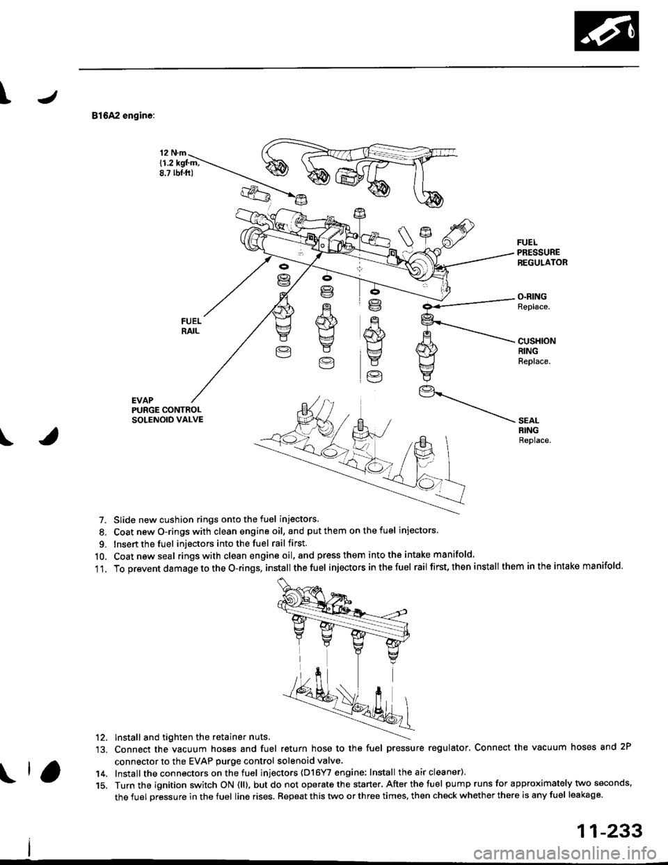
\J
81642 engine:
EVAP
12 N.m
{1.2 kgl m;8.? lbt.ft)
FUELPRESSUREREGULATOR
O.RINGReplace.
cusHloNRINGReplace.
PURGE CONTROLSOLENOID VALVE
\
SEALRINGReplace.
7. Slide new cushion rings onto the fuel injectors.
8. Coat newO-ringswith clean engineoil, and putthem onthefuel injectors.
9. Insert the fuel injectors into the fuel rail first.
10. Coatnewseal rings with clean engine oil,and press them intothe intake manifold.
11. To prevent damage to the O-rings, installthe fuel injectors inthefuel rail first, then install them inthe intake manifold.
'12. Install and tighten the retainer nuts.
13. Connect the vacuum hoses and fuel return hose to the fuel pressure regulator, Connect the vacuum hoses and 2P
connector to the EVAP purge control solenoid valve.
14. Install the connectors on the fuel inl'ectors (D16YI engine; Install the air cleaner).
15. Turn the ignition switch ON (ll), butdo not operate the starter. After the tuel pump runs for approximately two seconds,
the fuel pressure in the fuel line rises. Repeat this two or three times, then check whether there is any fuel leakage.
11-233