Page 603 of 2189

Inspection
1.surfaces lor
countershaftInspect the gear surfaces and bearang
wear and damage, then measure tne
at points A, B, and C.
Standard: A: 30.000 - 30.015 mm
(1.1811- 1.1817 inl
B: 35.984 - 36.000 mm
(1.i1167 - 1.4173 inl
C: 24.980 - 2i1.993 mm
{0.9835 - 0.9840 in)
Seryice Limit: A: 29.950 mm (1.1791 inl
B: 35.930 mm (1 '1146 in)
C: 24.930 mm 10.9815 in)
Check oil passages
for cloggrng-
ICheck for wearano oamage.
. lf any part of the countershaft is less than
service limit, replace it with a new one.
Inspect for runout.
Standard: 0.02 mm (0.001 inl max.
Seryice Limit: 0.05 mm {0'002 in)
. lf the runout is more than the service limit. replace
the countershaft with a new one.
the
2.
t,3. Install the parts on the countershait
Reassembly
CAUTION:
. Press the 3rd,4th, and sth gears on the countershaft
without lubrication.
. When installing the 3rd. 4th, and 5th geals, support
the shaft on steel blocks and installthe gears using a
pless.
NOTE: Reler to page 13-20 for reassembly sequence'
1. lnstall the needle bearing on the countershaft'
, 36x41 x 25.5mmNEEDLE BEARING
COUNTERSHAFT
2. Assemble the pans below as shown.
NOTE: Check that the fingers of the friction damper
are securely set in the grooves of the 1sv2nd syn-
chro hub.
2ND GEAR
39x/+4x27mmNEEDLE BEARING
SPACER COLLAR
FRICTION DAMPER
SYNCHRO RING
SYNCHRO SPRING
REVERSE GEAR
lST/2NOSYNCHRO HUB
SYNCHRO SPRING
SYNCHRO RING
FRICTION DAMPER
1ST GEAR
(cont'd)
13-23
Page 604 of 2189

Countershaft Assembly
Reassembly (cont'd)
4. Suppon the countershaft on a steel block as shownand install 3rd gear using the special tools and apress.
PRESS
35 mm l.o.07746-0030400
5. Install 4th gear using the special tools and a press.
DRlvER. 40 mm
DRIVER, 40 mm LO.07746 -0030100
ATTACHMENT,
07746- 0030100
ATTACHMENT,
DRIVER, 40 mm l.D.07746-0030100
ATTACHMENT,30 mm l.D.
35 mm LO.07746-0030400
6. Install 5th gear using the special tools and a Dress.
07746-00303005TI{ GEAR
.g
7. Install the bearings in the direction shown using thesDecialtools and a oress.
CAUTION: Install ths bearings with a maximumpressure ot 7.8 kN {800 kgt, 5,786 lbfl.
ATTACHMENT,30 mm l.D.07745 - q'303tl)
*1: 016Y7 engine*2: D16Y5, D16Y8 enginesThin edge of outerrace faces down,
8. Securely clamp the countershaft assemblv in
bench vise with wood blocks.
LOCKNUT
108+0r108N.m(11.0 * 0 - 11.0 kgt m. 79.6 - 0 * 79.6 tbf.ft)
Install the spring washer, tighten the locknut, thenstake the locknut tab into groove.
/rt-\
srySnap ring
lacss up.
\J
Page 621 of 2189

17. Instali the oil gutter Plate.
Install the oil guide plate and thrust shim on the
transmission housing.
Apply Iiquid gasket to the surface of the transmis-
sion housing mating with the clutch housing as
shown.
NOTE:
. Use liquid gasket {P/N 08718 - 0001 or
08718 - 0003).
. Remove the dirty oil fromthesealing surface.
. lf 5 minutes have passed after applying liquid
gasket, reapply it and assemble the housings.
. Allow it to cure at least 20 minutes after assem-
bly before filling the transmission with oil.
18.
19.
\
OIL GUTTER PTATE
TRANSMISSION HOUSING
Liquid gasket
20.lnstall the dowel pins and the transmission housing.
Lower the transmission housing with the snap ring
pliers, and set the snap ring into the groove of the
countershaft bearing.
NOTE: Check that the snap ring is securely seated
in the groove of the countershaft bearing
32 mm SEALING EOLT25 N.m (2.5 kgf.m, 18lbf.ftl
4.6 -8.3 mm10.14-0.33 inl
Install the 32 mm sealing bolt.
NOTE: Apply liquid gasket (P/N 08718 - 0001
08718 - 0003) to the threads.
(cont'd)
22.
13-41
Page 656 of 2189
Gountershaft Assembly
Disassembly
1. Securely clamp the countershaft assemblv in a
bench vise with wood blocks.
2. Raise the locknut tab from the groove in the coun-
tershaft, then remove the locknut and the spring
washer.
Remove the ball bearing using a bearing pulle. asshown.
BEARING PULLER
BALL BEARING
13-76
4, Remove the bearing outer race, then remove theneedle bearing using a bearing puller as shown.
BEARING PULLEF
BEARING
CAUTION: Romove the gears using a pr63 and the
stesl blocks as shown, Use of a ,aw-typo puller can
cause damage lo lhe gear tooth.
Support 4th gear on steel blocks, and press thecountershaft out of sth and 4th gears, as shown.
sTH GEAF
{TH GEAR
.(
a
ItI
Page 659 of 2189
9. Support the countershaft on a steel block, and
install 4th gear using the special tools and a press.
as 5nown.
ATTACHMENT,35 mm LD.07746 - 0030400
Support the countershaft on a steel block, and
install 5th gear using the special tools and a press,
as shown.
ATTACHMENT, 30 mm I,D,07746 - 0030300
10.
\
'1'1. Install the needle bearing, then install the ball bear-
ing using the special tools and a press as shown.
PRESSDRIVER,40 mm LD.07746 - 0030100
ATTACHMENT,30 mm LD.07746 - 0030300
J.-12.Securely clamp the countershaft assembly in a
bench vise with wood blocks.
lnstall the spring washer, tighten the locknut, then
stake the locknut tab into the groove.
LOCKNUT
108- 0- 108N.m 111.0- 0- 11.0kgt.m,
80+ 0* 80 lbf'ftl
WOOD BLOCKS
13-79
Page 674 of 2189
Transmission
Reassembly (cont'dl
Install the dowel pins.
Install the transmission housing by aligning thegroove in the housing with the finger on the stopfl ng.
GROOVE
21.
Lower the transmission housing with the snap ringpliers, and set the snap ring in the groove of thecountershaft bearing.
TRANSMISSIONHOUSING
13-94
(
23. Check that the snap ring is securely seated in thegroove of the countershaft bearing.
Dimension 6) as instalt6d: 4.6 - 8.3 mm(0.181 - 0.327 inl
24.Install the clutch line bracket, transmission hangerA and back-up light switch ctamp, then tighten thetransmission housing attaching bolts in the num_bered sequence shown below.
ATTACHING BOLTS8 x 1.25 mmTRANSMISSIONHANGER A27 N m 12.8 kgtm, 20 tbt.trl
BACK.UP LIGHTSWITCH CLAMP
lar---'o o
"W
Page 783 of 2189

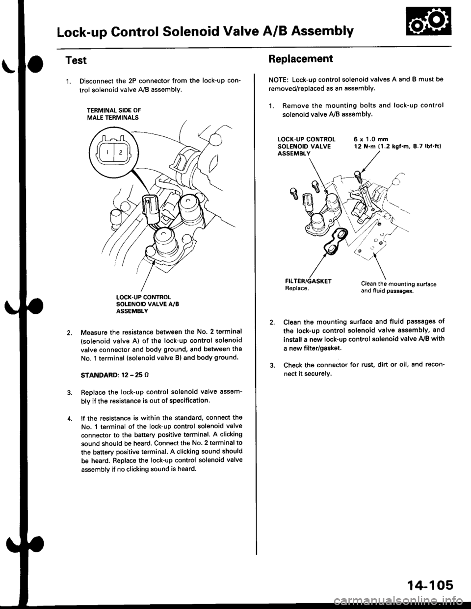
Lock-up Gontrol Solenoid Valve A/B Assembly
Test
'1, Disconnect the 2P connector from the
trol solenoid valve 1y'8 assembly.
TERMINAL SIOE OF
MALE TERMINALS
tocK-up con-
LOCK.UP CONTROLSOLENOID VALVE A/BASSEMBLY
Measure the resistance between the No. 2 terminal
(solenoid valve A) of the lock-up control solenoid
valve connector and body ground, and between the
No. 1 terminal (solenoid valve Bl and body ground.
STANDARD: 12 - 25 O
Replace the lock-up control solenoid valve assem-
bly if the resistance is out of specification.
lf the resistance is within the standard, connect the
No. 1 terminal of the lock-up control solenoid valve
connector to the battery positive terminal. A clicking
sound should be heard. Connsct the No. 2 terminal to
the battery positive terminal. A clicking sound should
be heard. Replace the lock-up control solenoid valve
assembly if no clicking sound is heard.
Replacement
NOTE: Lock-up control solenoid valves A and I must bs
removed/replaced as an assembly.
1. Remove the mounting bolts and lock-up control
solenoid valve Ay'B assemblv.
6 r 1.0 mm12 N.m (1.2 kgf.m,8.7 lbl.ftl
/:'-
Clean the mounting surfaceand fluid psssages.
Clean the mounting surface and fluid passages of
th6 lock-up control solenoid valve assembly, and
instsll a new lock-up control sol€noid valve Ay'B with
a new filtsr/gask€t.
Check the connector for rust, dirt or oil, and racon-
nect it securely.
1+105
Page 784 of 2189

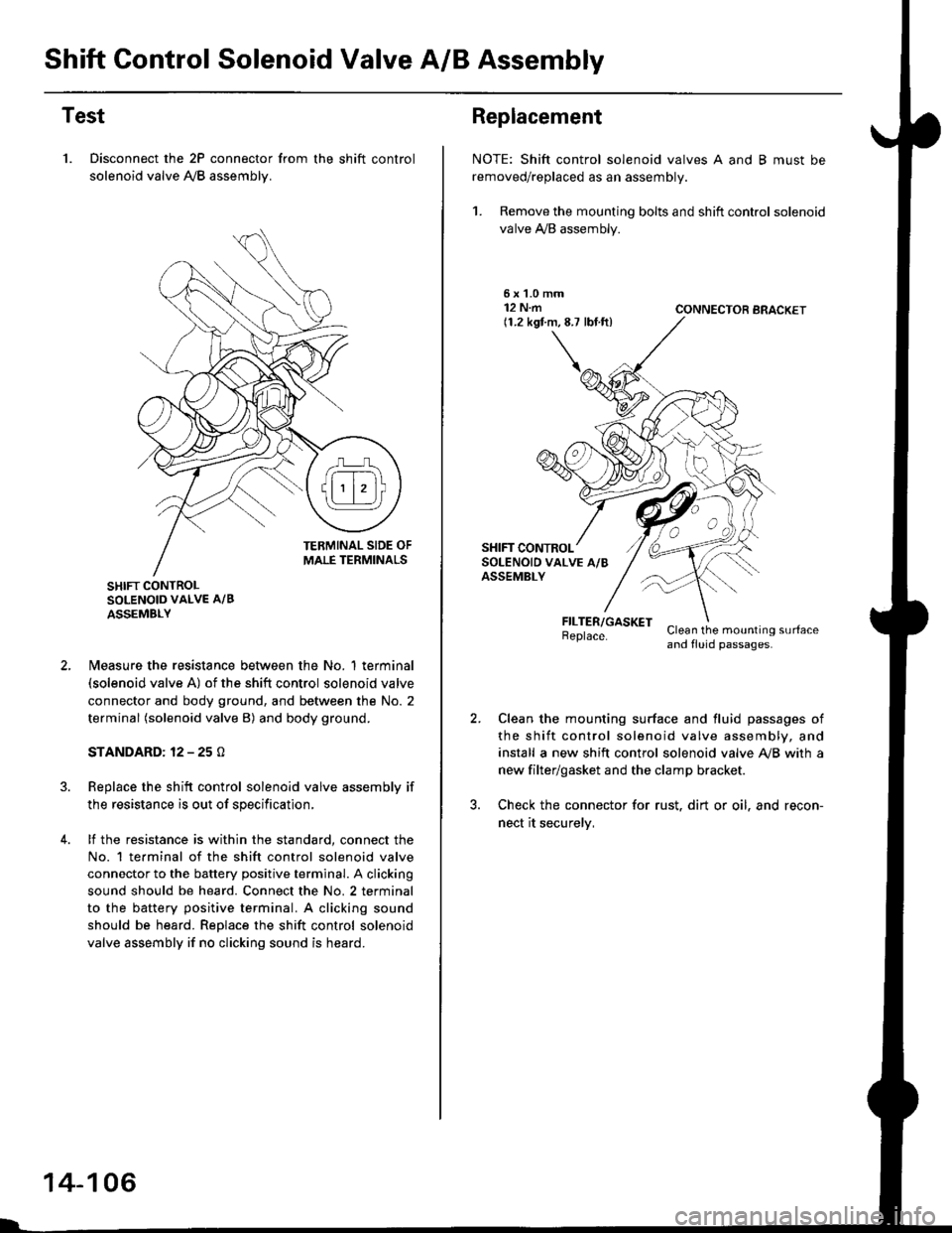
Shift Control Solenoid Valve A/B Assembly
Test
1. Disconnect the 2P connector from the shift control
solenoid valve A,/B assemblv.
SHIFT CONTROLSOLENOID VALVE A/B
ASSEMBLY
N4easure the resistance between the No. 1 terminal(solenoid valve A) of the shift control solenoid valve
connector and body ground, and between the No. 2
terminal (solenoid valve B) and body ground.
STANDARD: 12 - 25 O
Replace the shift control solenoid valve assembly if
the resistance is out of specification,
lf the resistance is within the standard, connect the
No. 1 te.minal of the shift control solenoid valve
connector to the battery positive terminal. A clicking
sound should be heard. Connect the No. 2 terminal
to the battery positive terminal. A clicking sound
should be heard. Replace the shift control solenoid
valve assembly if no clicking sound is heard.
14-106
Replacement
NOTE: Shift control solenoid valves A and B must be
removed/replaced as an assembly.
1. Remove the mounting bolts and shift control solenoid
valve A,/B assembly.
5xL0mm12 N.m(1.2 kgf.m,8.7 lbf.ft)CONNECTOR BRACKET
FILTER/GASKETBeplace.Clean the mounting surfaceand fluid passages.
Clean the mounting surface and fluid passages of
the shift control solenoid valve assembly, and
install a new shift control solenoid valve Ay'B with a
new filter/gasket and the clamp bracket.
Check the connector for rust. dirt or oil. and recon-
nect it securelv,