Page 1039 of 2189
Driveshafts
Disassembly (cont'dl
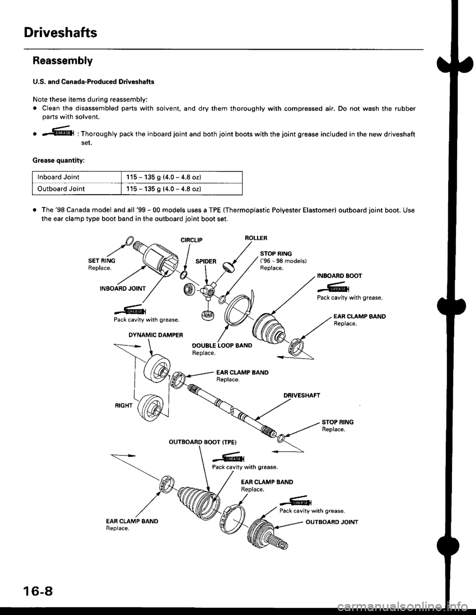
4. Mark the rollers and spider to identify the locations
of the rollers on the sDider, then remove the rollers.
B€ARING REMOVER{Commerciallv available}
STOP RING(Applicable to '96 - 98 modols andErazil-produced driveshafts)
Remove the circlip.
Mark the spider and driveshaft to identify the posi-
tion ot the spider on the shaft.
Remove the spider using a bearing remover.
Remove the stop ring (Applicable to '96 - 98 models
and Brazil-produced driveshafts).
Wrap the splines on the drivsshaft with vinyl tape to
prevent damage to the boot and dynamic damper.
DRIVESHAFT
1.
VINYL TAPE
DYNAMIC DAMPERCheck for damage.
Remove the inboard
dynamic damper.
INBOARO AOOTInspect for cracking,splitting and wear.
16-6
boot, and if necessary, the
Outboard Joint Side:
1. Lift up thc three tabs with a screwdriver, then
remove the boot bands, Take care not to damage
the boot.
NOTE:
. lf the boot band is a double loop type, lift up the
band bend.
. lf the boot band is a welded type, cut the boot
band.
. lfthe boot band is a locking tabs type, pry up the
tabs with a scr€wdriv€r and lift uo the snd of the
band.
2. Slide the outboard boot to the inboard ioint side.
TAB
OUTBOABD BOOT
Page 1041 of 2189
Driveshafts
Reassembly
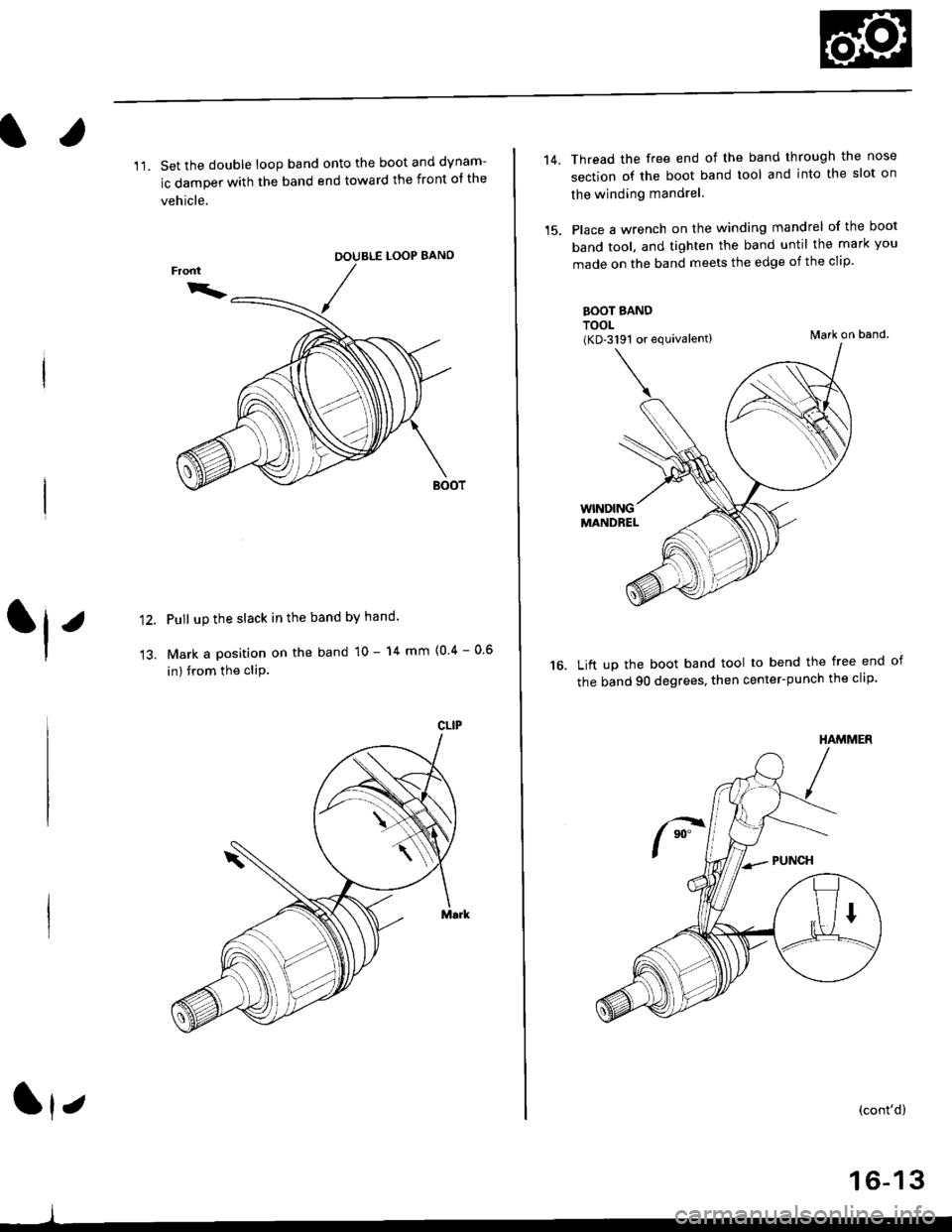
U.S. and Canada-Producad Driv€shafts
Note these items during reassembly'
. Clean the disassembled parts with solvent, and dry them thoroughly with compressed air, Do not wash the rubberpans with solvent.
o ;..jl@l : Thoroughly pack the inboard joint and both joint boots with the joint grease included in the new driveshaft
ser,
Grease quantity:
lnboard Joint115 - 135 g (4.0 - 4.8 oz)
Outboard Joint115 - 135 g (4.0 - 4.8 oz)
. The'98 Canada model and all '99 - 00 models uses a TPE (Thermoplastic Polyester Elastomerl outboard joint boot. Use
the ear clamp type boot band in the outboard joint boot set.
STOP RING('96 - 98 models)
-6rPack cavity with grease.
DYNAMIC DAMPER
OOUBI.S LOOP BANDReplace.
INBOARD BOOT
-6lPack cavity with grease.
EAB CLAMP BANDReplace.
STOP RINGReplace.
EAR CLAMP BANDReplace.
DRIVESHAFT
OUTBOARDBOOT ITPE)
-6ll
, Pack cavity with grease.
EAR CLAMP BANDReplace.
-G.1
CIRCLIP
16-8
OUTBOARD JOINT
Page 1043 of 2189
Driveshafts
Reassembly (cont'dl
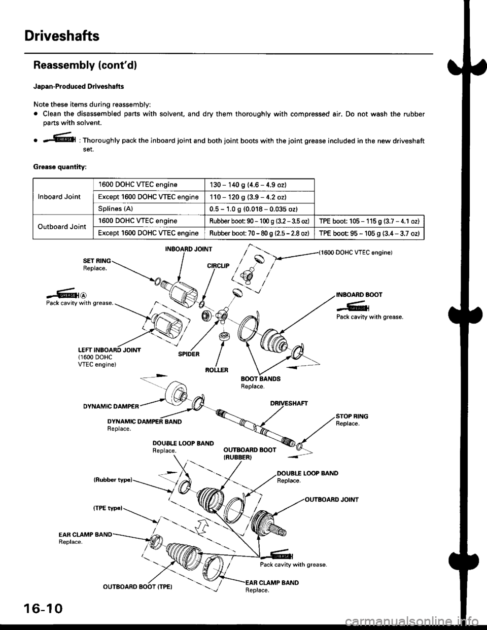
Japan-Produced Driveshafts
Note these items during reassembly.
. Clean the disassembled pans with solvent, and dry them thoroughly with compressed air. Do not wash the rubber
parts with solvent.
o r@l : Thoroughly pack the inboard joint and both joint boots with the joint grease included in the new driveshaft
set.
Grease quantity:
Inboard Joint
1600 DOHC WEC engine130 - 140 9 (4.6 - 4.9 oz)
Except 1600 DOHC VTEC engine110 - 120 g (3.9 - 4.2 oz)
Splines (Al0.5 - 1.0 g (0.018 - 0.035 oz)
Outboard Joint
'1600 DOHC WEC engineRubber boot 90 - 'l 00 g (3.2 - 3.5 oz)TPE boot; 105 - 115 9 (3.7 - 4.1 oz)
Except 1600 DOHC VTEC engineRubber boot 70 - 80 g |'2.5 - 2.8 ozlTPE boot 95 - 105 g (3.4 - 3.7 oz)
{1600 DOHC VTEC angine)
SET RINGReplace.
-6{@INBOARD BOOT
-6;Pack cavity with grease.
Pack cavity with grease.
DYNAMIC DAMPER
DYNAMICReplace.
DOUA|.I Lq)P BANDReplace.
(Rubber typc)LOOP BANDReplace.
Pack cavity with grease-
CLAMP BAND
],*"u, ,"^S
/ t'.t$ ,''
,/s
-'-
OUTBOARD BOOTIRUEBER)
16-10
tttt t*' -----_.r...-
._
Replace.
Page 1044 of 2189
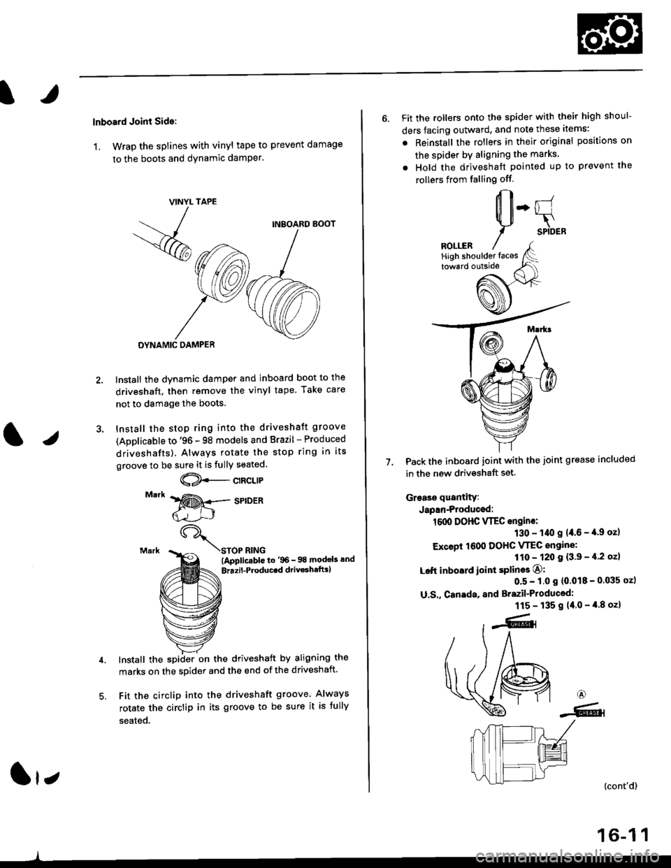
lnboard Joint Side:
1, Wrap the splines with vinyl tape to prevent damage
to the boots and dynamic damPer.
TAPE
INBOARD BOOT
DYNAMIC DAMPER
Install the dynamic damper and inboard boot to the
driveshaft, then remove the vinyl tape. Take care
not to damage the boots.
Install the stop ring into the driveshaft groove
(Applicsble to '96 - 98 models and Brazil - Produced
driveshafts). Always rotate the stop ring in its
groove to be sure it is fully seated.
@--c't"t't
STOP RING(ApplicablG to'96- 98 modob and
Brrzil-Producrd drivoshaftrl
Install the spiiler on the driveshaft by aligning the
marks on the sDider and the end of the driveshaft.
Fit the circlip into the driveshaft groove. Always
rotate the circlip in its groove to be sure it is fully
seated.
VINYL
- -
/
-<@
lr;
6. Fit the rollers onto the spider with their high shoul-
ders facing outward, and note these items:
. Reinstall the rollers in their original positions on
the spider by aligning the marks
. Hold the driveshaft pointed up to prevent the
rollers from falling off.
Pack the inboard joint with the joint grease included
in the new driveshaft set.
Grease quantity:
Japan-Produced:
1600 DOHC VTEC ongine:
130 - 1/t0 g 14.6 - '[.9 oz)
Except 1600 DOHC VTEC angine:
110 - 120 I {3'9 - il'2 oz}
Left inboard ioint splines O:
0'5 - 1.0 s (0.018 - 0'035 oz)
U.S,, Canada, and Brazil'Produced:
115 - 135 g (40-4.8ozl
7.
6
-6.l
(cont'd)
16-1 1
High shoulder faces
Page 1045 of 2189
Driveshafts
Reassembly (cont'dl
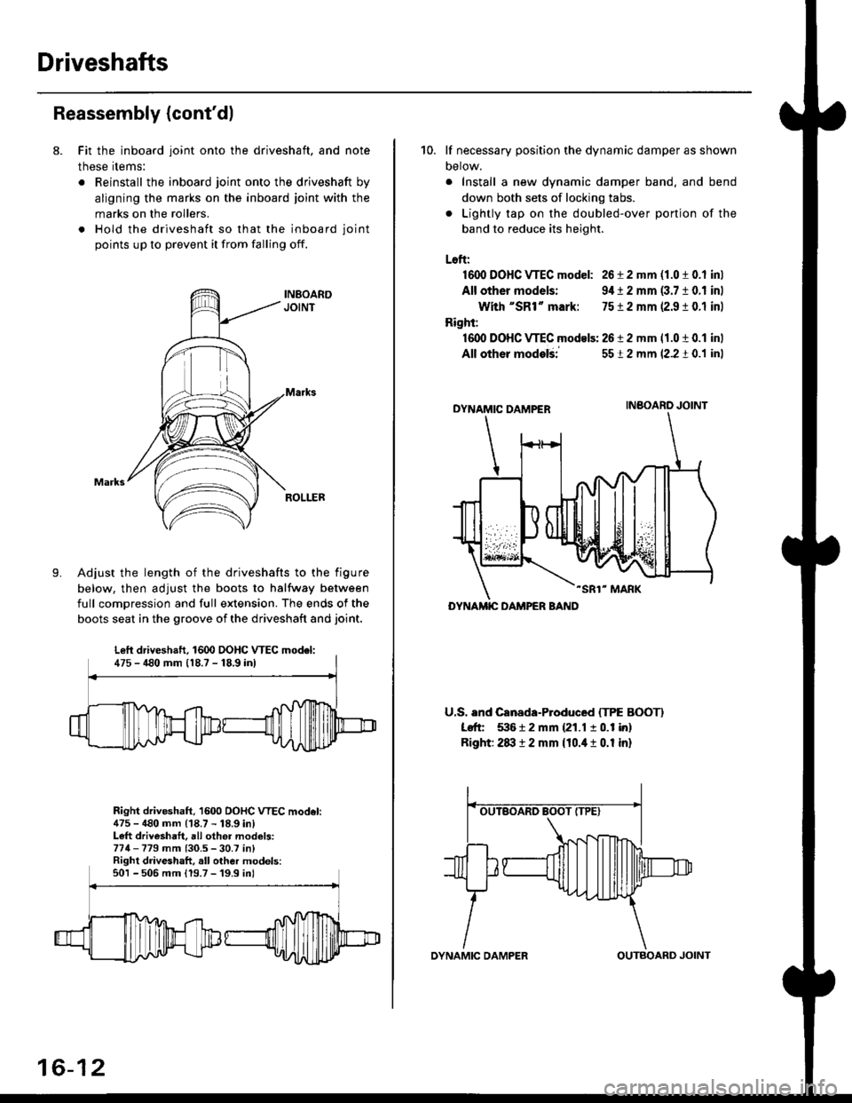
8. Fit the inboard joint onto the driveshaft, and note
these items:
. Reinstall the inboard joint onto the driveshaft by
aligning the marks on the inboard joint with the
marks on the rollers.
. Hold the driveshaft so that the inboard joint
points up to prevent it from falling off.
Adjust the length of the driveshafts to the figure
below, then adjust the boots to halfway between
full comDression and full extension. The ends of the
boots seat in the groove of the driveshaft and joint.
Right driveshaft, 1600 OOHC VTEC model:475 - 480 mm (18.7 - 18.9 in)Left driveshaft, all othei models:774-779 mm (30.5 - 30.7 in)Right driveshaft, all other models:501 - 506 mm 119.7 -'19.9 inl
Left driveshaft. 1600 DOHC WEC model:475 - 480 mm 118.7 - 18,9 inl
16-12
OYNAMIC DAMPEROUTBOARD JOINT
10. lf necessary position the dynamic damper as shown
Detow.
. Install a new dynamic damper band. and bend
down both sets of locking tabs.
. Lightly tap on the doubled-over ponjon of the
band to reduce its height.
Loft:
1600 DOHC VTEC model: 26 i 2 mm (1.0 t 0.1 inl
All other models: 9,1t 2 mm (3.7 10.1 inl
With "SR1" mark: 7512 mm 12.9 ! 0.1 inl
Right:
16dl DOHC VTEC models: 2612 mm 11.0 t 0.1 inl
All other modelii
DYNAMIC DAMPER
-SR1" MARK
U.S. and Canada-Produced ITPE BOOTI
Left 53612 mm {21.1 10.1 in}
Right: 2txt 12 mm {10.it 1 0.1 in}
5512 mm (2.2 t 0.1 inl
INBOARO JOINT
DYNAMIC DAMPER BAND
Page 1046 of 2189
l.
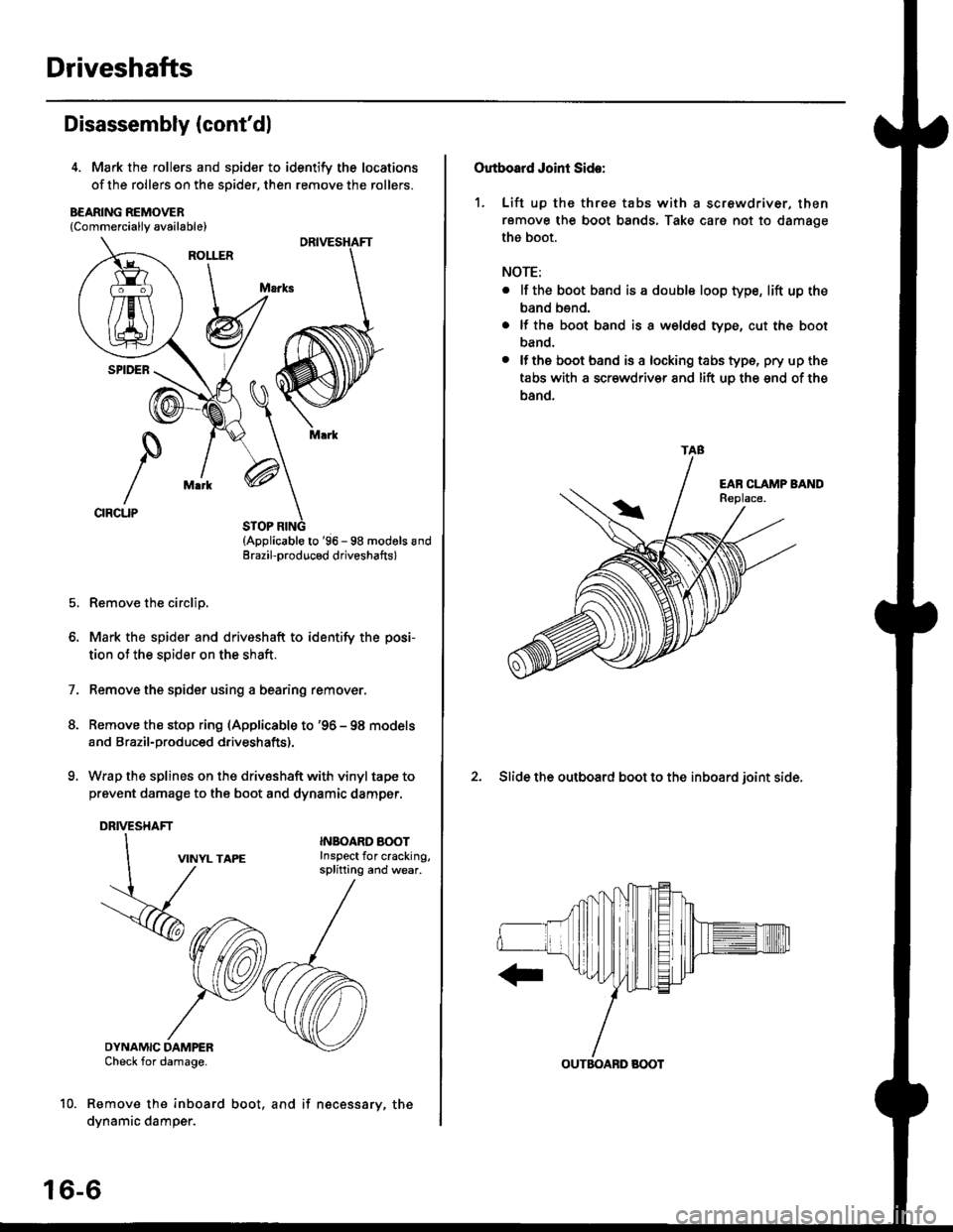
11. Set the double loop band onto the boot and dynam-
ic damper with the band end toward the front ot the
vehicle.
LOOP BANO
Pull up the slack in the band bY hand
Mark a position on the band 10 - 14 mm {0 4 - 0 6
in) from the cliP.
DOUBLE
,
1')
13.
CLIP
Ip
14.
15.
Thread the free end of the band through the nose
section of the boot band tool and into the slot on
the winding mandrel.
Place a wrench on the winding mandrel of the boot
band tool, and tighten the band until the mark you
made on the band meets the edge of the clip.
Mark on band.
Lift up the boot band tool to bend the free end
the band 90 degrees, then center-punch the clip'16.
(cont'd)
16-13
(KD-3191 or equivalent)
HAMMER
Page 1052 of 2189
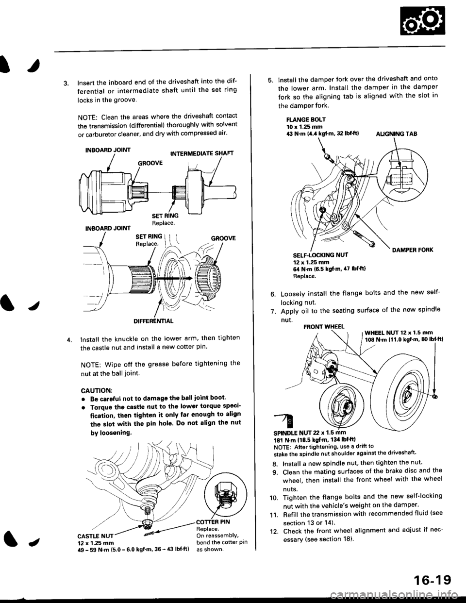
3. lnsert the inboard end of the driveshaft into the dif-
terential or intermediate shaft until the set ring
locks in the groove
NOTE: Clean the areas where the driveshaft contact
the transmission (differential) thoroughly with solvent
or carburetor cleaner, and dry with compressed air'
INBOARD JOINT
INBOARD JOINTReplace.
GROOVE
an
DIFFERENTIAL
lnstall the knuckie on the lower arm. then trghten
the castle nut and install a new cotter pin
NOTE: wipe off the grease before tightening the
nut at the ball ioint.
CAUTION:
. Be careful not to damago the ball ioint boot'
. Torque the castle nut to the lower torque sp€ci-
fication, thsn tighten it only far enough to align
the slot with th€ pin hol6. Do not align the nut
by loosening.
CASTLE NUT12 x 1 .25 mm
COTTER PINReplace.On reassemblY,bend the cotter pinJi$ - 59 N.m 15.0 - 6.0 kgl m,35 - 43 lbf ftl
16-19
5. lnstall the damper tork over the driveshaft and onto
the lower arm. Install the damper in the damper
fork so the aligning tab is aligned with the slot in
the damPer fork.
FLANGE BOLTl0 r 1.25 mmrit N.m t4.a kgf.m, 32 lbf.ft) AIIGN|NG TAB
1.
SELF-LOGKING NUT12 x 1.25 mm6,1N.m 16.5 kgi.m, a7 lbfftl
Replace.
Loosely install the flange bolts and the new self-
locking nut.
Apply oil to the seating surface of the new spindle
nut.
181 N m 118.5 kgt'm, 13il lbt'ftl
NOTE: Aftortightening, use a drift to
stake the spindle nut shoulder against the drivoshaft'
8. Install a new spindle nut, then tighten the nut'
9. Clean the mating surfaces ot the brake disc and the
wheel. then install the front wheel with the wheel
nuts.
10. Tighten the flange bolts and the new self-locking
nut with the vehicle's weight on the damper.
11. Refill the transmission with recommended fluid (see
section 13 or 14).'t2. Check the front wheel alignment and adjust if nec-
essary (see section 18),
FRONT WHEEL
SPINDLE NUT 22 x 1.5 mm
WHEEL NUT 12 x 1.5 mm108 N.m (11.0 kgl'm, g) lbl ftl
Page 1054 of 2189
Disassembly
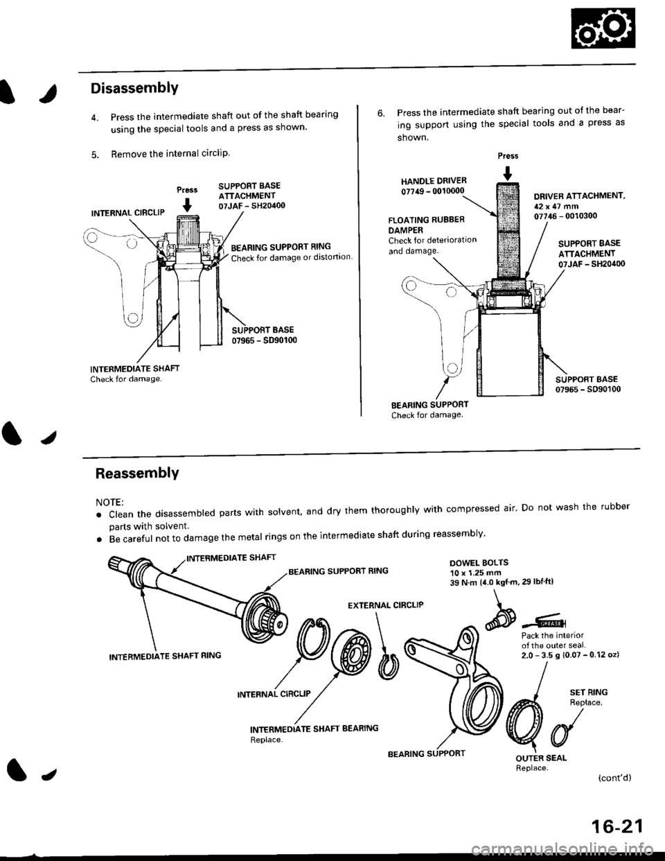
Press the intermediate shaft out of the shaft bearing
using the special tools and a press as shown.
Remove the internal circliP
Press
I
SUPPORT BASEATTACHMENT07JAF - SH20400INTERNAL CIBCLIP
BEARING SUPPORT RING
Check for damage or distortion
6. Press the intermediate shaft bearing out ot the bear-
ing support using the special tools and a press as
shown.
HANOLE DRIVER
0?749 - 00'10000
Press
I
DRIVER ATTACHMENT,12x47 mm07746 - 0010300FLOATING RUBBEB
DAMPERCheck for deterioration
and oamage.SUPPORT BASE
ATTACHMENT07JAF _ SH20it00
BEARING SUPPORT
Check for damage
I sErR'NG
A4 Reolace
VUOUTER SEALReplace.(cont'd)
ReassemblY
NOTE:
. clean the disassembted parts with solvent, and dry them thoroughly with compressed air' Do not wash the rubber
parts with solvent.
. Becareful not to da mage the metal ringson the intermediate shaftduring reassembly'
BEARING SUPPORT RINGDOWEL BOLTS10 x 1.25 mm39 N.m 14.0 kgf.m,29 lbIftl
EXTERNAL CIRCLIP
Pack the interiorof the outer seal.2.0-35s10.07-012oz)
INTERNAL CIRCLIP
INTERMEDTATE SHAFT BEARING
Replace,
INTERMEDIATE SHAFT RING
lJ
16-21