Page 832 of 2189
Gountershaft
Inspection (cont'dl
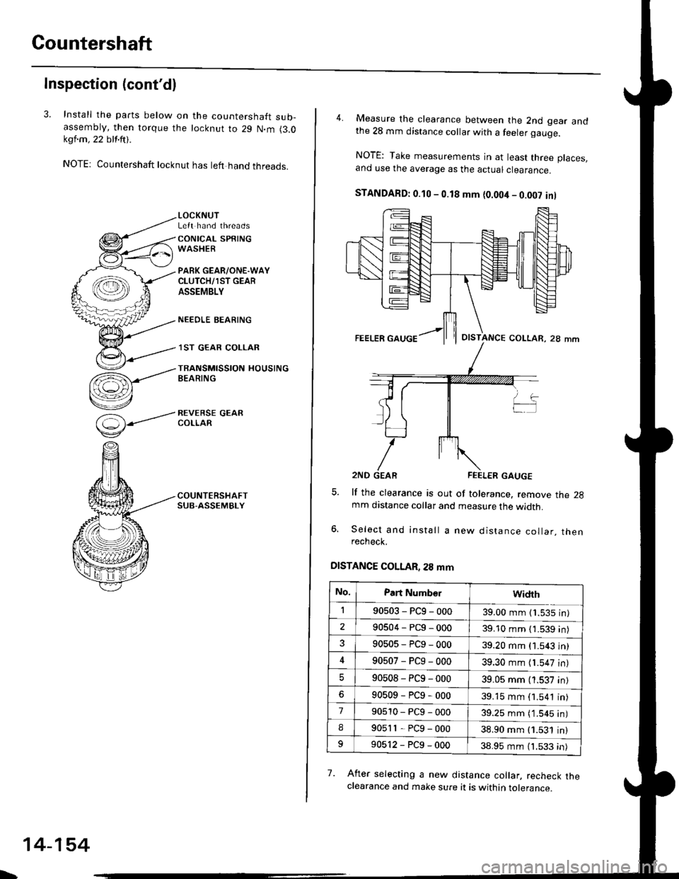
3. Install the parts below on the countershaft sub-assembty, then torque the locknut to 29 N.m (3.0kql.m , 22 blf.ftt .
NOTE: Countershaft locknut has left hand threads.
(=)-----'
v
LOCKNUTLeft hand threads
CONICAL SPRINGWASHER
PARK GEAR/ONE.WAYCLUTCH/1ST GEARASSEMBLY
NEEOLE BEARING
.I ST GEAR COLLAR
TRANSMISSION HOUSINGBEARING
REVERSE GEARCOLLAR
\
14-154
4. Measure the clearance between the 2nd gear andthe 28 mm distance collar with a feeler gauge.
NOTE: Take measurements in at least three places.and use the average as the actuar ctearance.
STANDAFD: 0.10 - 0.18 mm {0.004 - 0.002 inl
lf the clearance is out of tolerance. remove the 2gmm distance collar and measure the width.
Select and install a new distance collar, thenrecheck.
DISTANCE COLLAR, 28 mm
7. Afret selecting a new distance collar, recheck theclearance and make sure it is within tolerance.
OISTANCE COLLAR, 28 mm
No.Part Numb€rwidrh
190503-PCg-00039.00 mm (1.535 in)
290504-PCg-00039.10 mm { 1.539 in)
90505-PCg-00039.20 mm (1.543 in)
90507-PCg-00039.30 mm {1.547 in)
90508-PC9-00039.05 mm (1.537 in)
90509-PCg-00039.15 mm (1.541 in)
790510-PCg-00039.25 mm ( 1.545 in)
I90511-PCg-00038.90 mm (1.531 in)
90512-PCg-00038.95 mm (1.533 in)
Page 846 of 2189
Differential
Diff erential Carrier Replacement
L Remove the final driven gear from the differential
carrier.
NOTE: The final driven gear bolts have left-hand
threads.
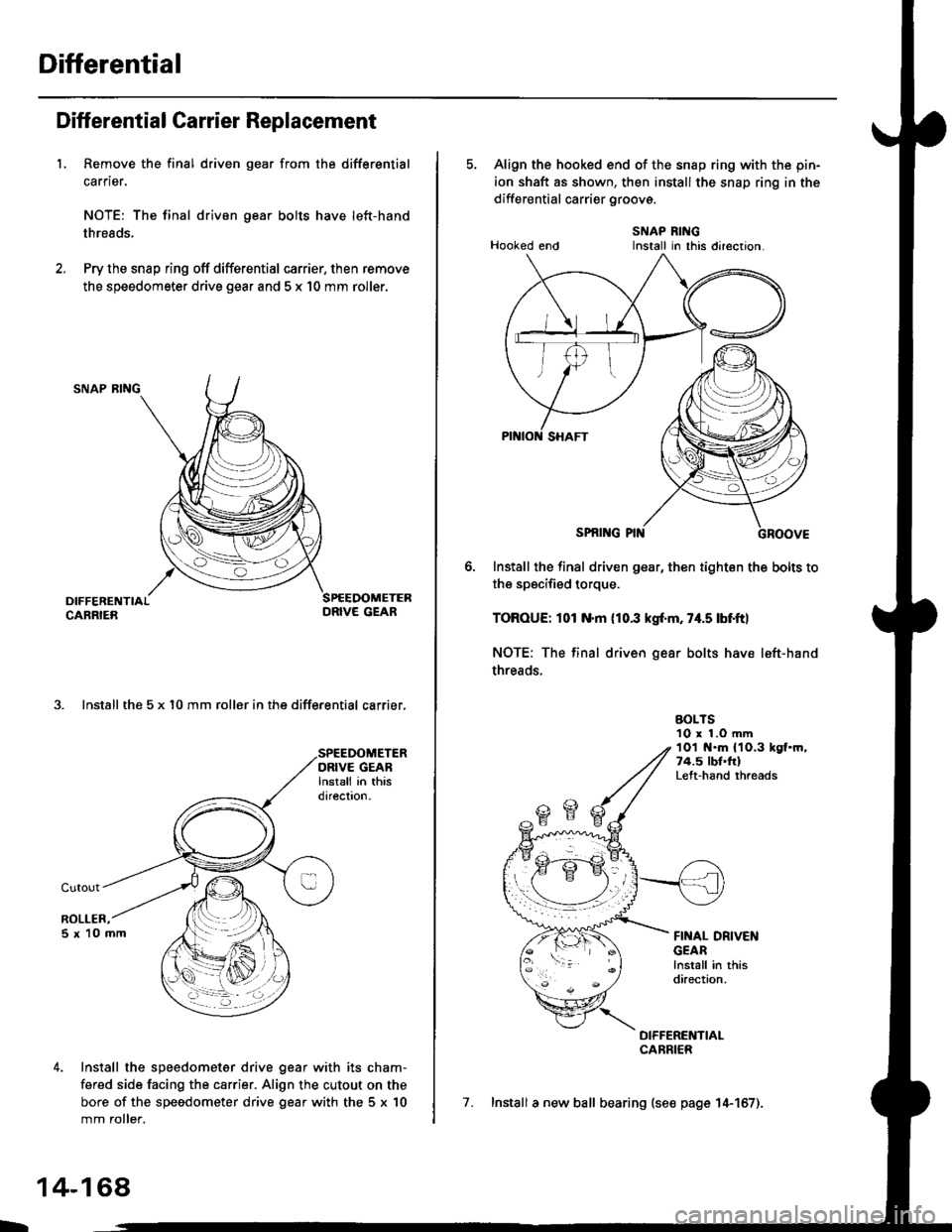
Pry the snap ring off differential carrier, then remove
the speedometer drive gear and 5 x 10 mm roller.
SNAP RING
3. Install the 5 x l0 mm roller in the differential carrier,
Install the speedometer drive gear with its cham-
fered side facing the carrier. Align the cutout on the
bore of the speedometer drive gear with the 5 x 10
mm roller.
L
14-168,
5. Align the hooked end of the snap ring with the pin-
ion shaft as shown, then install the snap ring in the
differential carrier groovs.
SNAP RINGHooked end Install in this direction.
SPNI G PIN
Install the final driven gear, then tighten the bolts to
the specified torque.
TOROUE: 101 N.m (10.3 kgf'm, 74.5 lbf.ftl
NOTE: The final driven gear bolts have left-hand
threads.
BOLTS10 r 1.O mm1Ol t{.m 11O.3 kgf.m,74.5 lbl.frlLeft-hand rhreads
FINAL DRIVENGEARlnstall in thisdirection.
DIFFERENTIALCARRIER
7. Install a new ball bearing (se€ page 14-157).
Install in this direclon.
Page 848 of 2189
Differential
Oil Seal Installation/Side Clearance (cont'd)
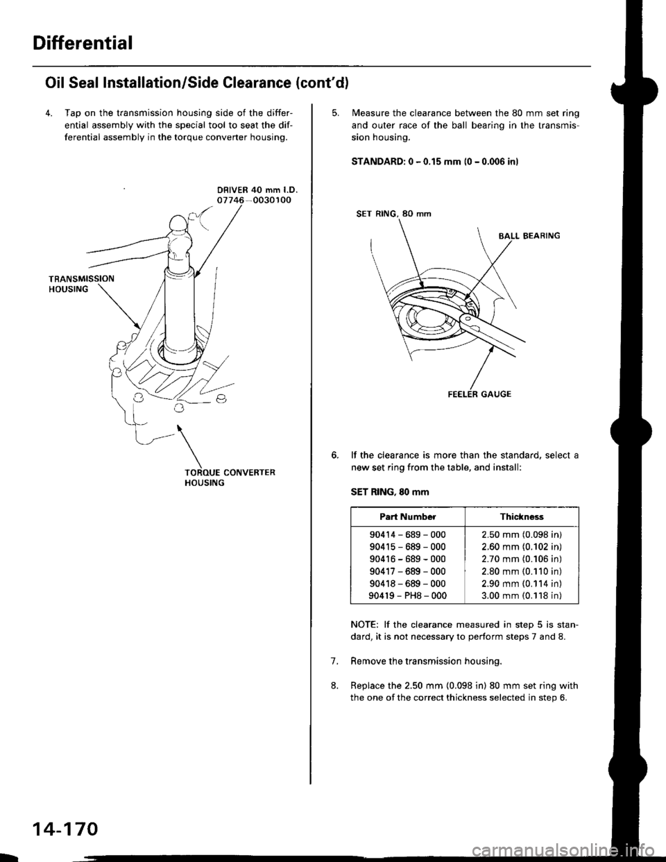
4. Tap on the transmission housing side of the differ-
ential assembly with the special tool to seat the dif-
ferential assembly in the torque converter housing.
DRIVER 40 mm l.D.
L
14-170
5. N4easure the clearance between the 80 mm set ring
and outer race of the ball bearino in the transmis-
sion housing.
STANDARD: 0 - 0.15 mm (0 - 0.006 inl
SET RING, 80 mm
BALL BEARING
lf the clearance is more than the standard, select a
new set ring from the table, and install:
SET RING, 80 mm
NOTE: lf the clearance measured in step 5 is stan-
dard, it is not necessary to perform steps 7 and 8.
Remove the transmission housing.
Replace the 2.50 mm (0.098 in) 80 mm set ring with
the one of the correct thickness selected in step 6.
7.
Part NumberThickness
90414-689-000
904r5-689-000
90416-689-000
90417-689-000
90418-689-000
904r9-PH8-000
2.50 mm (0.098 in)
2.60 mm {0.102 in)
2.70 mm {0.106 in)
2.80 mm (0.110 in)
2.90 mm (0.114 in)
3.00 mm (0.118 in)
Page 850 of 2189
Torque Converter Housing Bearings
Mainshaft Bearing/Oil Seal Replacement
1.Remove the mainshaft bearing and oil seal using
the special tools as shown.
3/8"16 SLIOE HAMMER
ADJUSTAELE BEARINGPULLER, 25 - ilo mm07736 - A01000a
L
14-172
2. Drive in the new mainshaft bearing until it bottomsin the housing using the special tools as shown.
DRIVER077€ - 0010000
lnstall the new oil seal flush with the housing using
the special tools as shown.
DBIVER07749 - 0o l0(xt0
ATTACHMENT,72x75 mfi07746 - 001 0600
Page 857 of 2189
17.
18.
19.
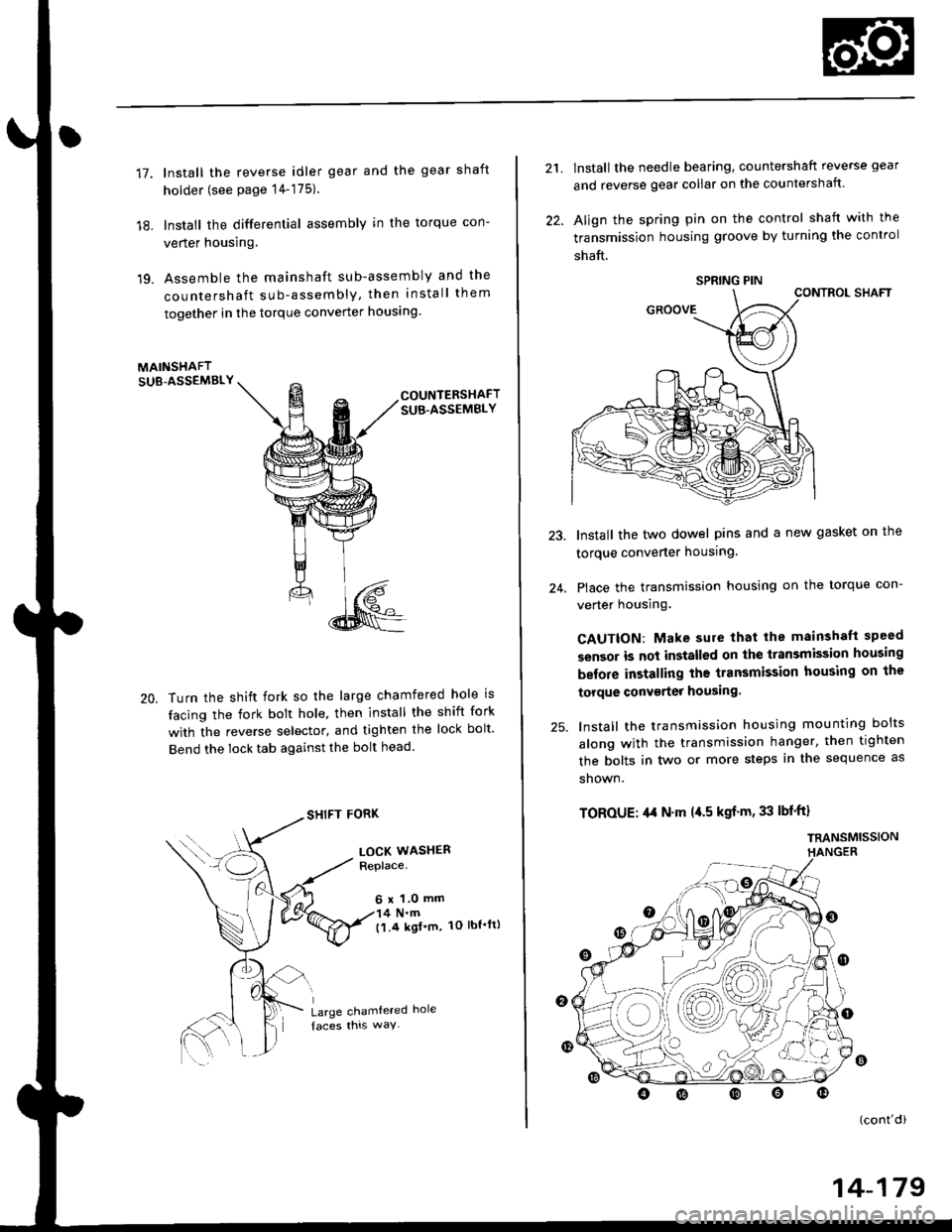
lnstall the reverse idler gear and the gear shaft
holder (see page 14-175).
lnstall the differential assembly in the torque con-
verter housing.
Assemble the mainshaft sub-assembly and the
countershaft sub-assembly, then install them
together in the torque converter houslng
MAINSHAFTSUB-ASSEMBLY
20,
COUNTERSHAFTSUB.ASSEMBLY
Turn the shift fork so the large chamfered hole is
tacing the fork bolt hole, then install the shift fork
with the reverse selector, and tighten the lock bolt'
Bend the lock tab against the bolt head
SHIFT FORK
LOCK WASHERReplace.
6 x 1.0 mm4 N.m('l.4 kgl'm, 1O lbt'ft)
Large chamtered hole
21.
22.
lnstall the needle bearing, countershaft reverse gear
and reverse gear collar on the countershaft.
Align the spring pin on the control shaft with the
transmission housing groove by turning the control
shaft.
CONTROL SHAFT
Install the two dowel pins and a new gasket on the
torque converter housing.
Place the transmission housing on the torque con-
verter housing.
CAUTION: Make sure that lhe mainshaft speed
sensor is not installed on the transmission housing
before installing the transmission housing on the
torque conv€rter housing.
lnstall the transmission housing mounting bolts
along with the transmission hanger, then tighten
the bolts in two or more steps in the sequence as
shown.
TOROUE: ,l,t N'm l{.5 kgf'm, 33 lbf'ft}
TRANSMISSIONHANGER
24.
o
(cont'di
SPRING PIN
14-179
Page 858 of 2189

Transmission
26. Slip the special tool onto the mainshaft as shown,
MAINSHAFT HOLDER07GAB - PF50101
Installthe park lever on the control shaft.
Assemble the one-way clutch and the park gearwith the countershaft lst gear (see page l4-1S5).
Install the countershaft lst gear collar. needle bear_ing, and the countershaft 1st gearlpark gear assembly
Reassembly (cont'dl
on the countershaft.
lSTCLUTCH PARKASSEMBLY GEAR
27.
28.
29.
30.Install the park pawl shaft, spring, pawl, and pawlstop on the transmission housing, then engage thepark pawlwith the park gear.
14-180
31. Install the mainshaft 1st gear collar on the main_shaft.
32. Wrap the shaft splines with tape to prevent the O-rings, then install new O-rings on the mainshaft,
33. Assemble the thrust washer, thrust needle bearing,needle bearing, and mainshaft ?st gear in the lstclutch assembly, then install them on the mainshaft.
34. Install new conical spring washers and locknuts oneach shaft.
CAUTION: Install the conical spring washers in thedirection shown.
MAINSHAFTLOCKNUTLeft hand threads
CONICAL SPRING WASHERSinstall in this direction.
35. Tighten the locknuts to the specified torque.
NOTE:
. Do not use an impact wrench. Alwavs use atorque w.ench to tighten the locknut.. Mainshaft and countershaft locknuts have left_hand threads.
TOROUE:
MAINSHAFT 78 N.m (8.0 kgf.m, 58 tbf.ft)COUNTERSHAFT t03 N.m 1r0.5 kgf.m, 75.9 tbt.ftl
Page 1007 of 2189
Differential
Bearing Replacement
NOTE: Check the bearings for wear and rough rotation.
lf the bearings are OK, removal is not necessary.
'1. Remove the ball bearings using a bearing puller.
Install the new ball bearings
with a press as shown.
BAI-L BEARING
using the special tool
ORIVER 10 mm l.O.
07746 - 0030100
14-330
BALL BEARING
Differential Carrier Replacement
1. Remove the final driven gear from the differential
carner.
NOTE: The final driven gear bolts have left-hand
threads.
BOLTS10 x 1,0 mm98 N'm 110,0 kgf.m,72 tbl.ttlLeft-hand threads
DIFFERENTIALCARRIER
Install the final driven gear with its chamfered side
on the inner bore facing the differential carrier.
Tighten the bolts to the specified torque in a crisscross
Paftern.
TOROUE: 98 N.m (10.0 kgt.m, 72 lbf.ft)
Page 1118 of 2189
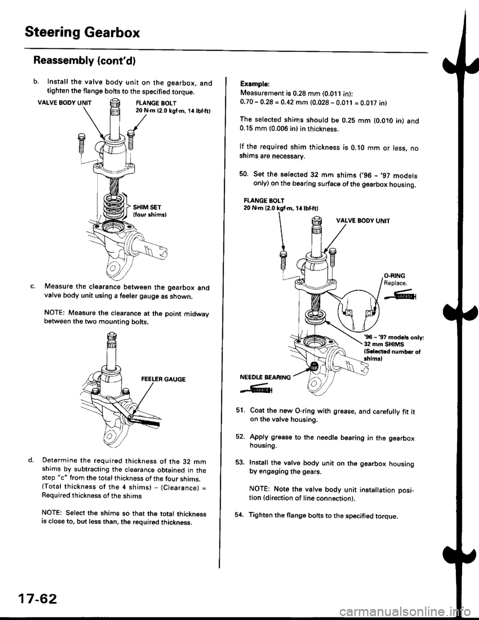
Steering Gearbox
Reassembly (cont'd)
b. Install the valve body unit on the gearbox, andtighten the flange bolts to the specified torque.
VALVE BODY UNTTFLANGE BOLT20 N.m {2.0 ksl.m, 14lbI.ftl
Measure the clearance between the gearbox andvalve body unit using a feeler gauge as shown.
NOTE: Measure the clearance at the point midwaybetween the two mounting bolts.
Determine the required thickness of the 32 mmshims by subtracting the clearance obtained in thestep "c" from the total thickness of the four shims.(Total thickness of the 4 shims) - (Clearance) =
Required thickness of the shims
NOTE: Select the shims so that the total thicknessis close to. but less than, the required thickness,
17-62
54.
Example:
Measurement is 0.28 mm (0.011 in):0.70 - O.28 = 0.42 mm (0.028 - 0.011 = O.Ot7 inl
The selected shims should be 0.28 mm lO.OtO in) and0.15 mm {0.006 in} in thickness.
lf the r€quired shim thickness is 0.10 mm or less, noshims are necessarv.
50. Sot the selected 32 mm shims (,96 - ,97 modelsonly) on the bearing surface ofthe gearbox housing.
FLANGE BOLT20 N.m 12.0 ksf.m, 1l lbtftl
VALVE BODY UNIT
'96 - 37 modsl3 only:32 mm SHIMS{S.loctod numb.r of3him!l
Coat ths new O-ring with grease, and carefully fit iton the valve housing.
Apply grease to the needle bearing in the gearboxhousing.
Install the valve body unit on the gearbox housingby engaging the g€ars.
NOTE: Note the valve body unit installation posi-
tion (direction of line connection).
Tighten the flange bolts to the specified torque.
O-RINGReplace.
-A-l
NEEDLE BEARING
-R1
51.
EA