Page 1071 of 2189

Component Locations
I
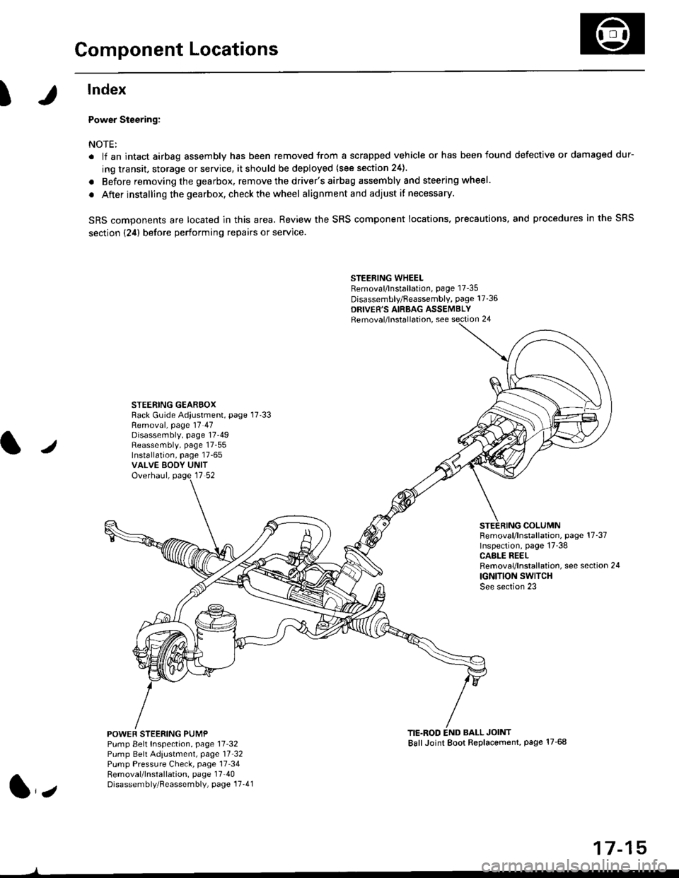
lndex
Power Steering:
NOTE:
. li an intact airbag assembly has been removed trom a scrapped vehicle or has been found defective or damaged dur-
ing transit. storage or service, it should be deployed (see section 24).
. Before removing the gearbox, remove the driver's airbag assembly and steering wheel.
. After installing the gearbox, checkthewheel alignmentand adjust if necessary.
SRS components are located in this area. Review the SRS component locations. precautions, and procedures in the SRS
section {24} before performing repairs or service.
STEERING WHEELRemoval/lnstallation, page 17-35
Disassembly/Feassembly, page 17-36
DRIVER'S AIRBAG ASSEMBLYRemoval/lnstallation, see section 24
STEERING GEAREOXRack Guide Adiustment, page 17'33
/
Removal, page 17 47Disassembly, page 17-49Reassembly, page 17-55Installation, page 17-65VALVE EODY UNITOverhaul, page 17 52
COLUMNFemoval/lnstallation, page 17-37Inspection, page 17-38CASLE REELRemoval/lnstallation, see section 24
IGNITION SWITCHSee section 23
POWEF STEERING PUMPPump Belt Inspection, page 11-32Pump Belt Adiustmenl, page 11'32Pump Pressure Check, page 17 34Removal/lnstallation, page 17'40Disassembly/Reassembly, page 17-41
TIE.ROD END BALL JOINTBallJoint Boot Replacement, page 17-68
1,,
17-15
Page 1084 of 2189

Troubleshooting
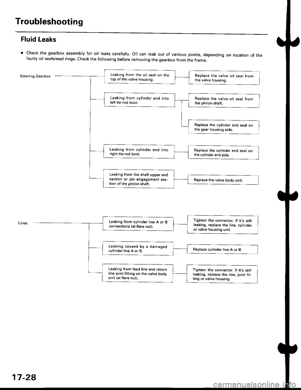
Fluid Leaks
Check the gearbox assembly for oil leaks carefully. Oil can leak out of various points. depending on location of thefaulty oil seals/seal rings. Check the following before removing the gearbox from the frame_
Steering GearboxLeaking from the oil seal on thetop of the valve housing.Replace the valve oil seal fromthe valve housing.
Leaking from cylinder end intoleft tie rod boot.Replace the valve oil seal tromthe pinion shaft.
Replace the cylinder end seal onthe gear housing side.
Leaking lrom cylinder end intoright tie-rod boot.Replace the cylinder end seal onthe cylinder end side.
Leaking lrom the shaft upper endsectron or pin engagement sec,tion ol the pinion shaft.Replace the valve body unit.
Tighten the connector. lf it's stillleakinO, replace the Iine, cylinderor valve housing unit.
Leaking from cylinder line A or Bconnections {at tlare nut}.
Leaking caused by a damagedcylinde.line A or B.Replace cvljnder line A or B.
Leaking from feed line and returnline ioint fitting on the valve bodyunit (at flare nut).
Tighten the connector. ll it's stillleaking, replace the line,,oint fit,ting or valv6 housing.
17-2a
Page 1087 of 2189
ISteering Linkage and Gearbox
TIE-ROD END BALL JOINT
Inspect for faulty movement
and damage.
STEERING COLUMN
Inspect for loose column
mounting bolts and nuts
BOOTInspectdamage and deteriorataon
STEERING GEARBOXlnspect for loose mounting bolts.
GEARBOX MOUNTING CUSHIONS
Inspect f or deterioration
STEERING JOINTSCheck for loose joint bolts.
l./
TIE-ROD LOCKNUTfor loose locknut
BALL JOINT BOOT
Inspect for damage and deteriorataon'
See page 17-68lor replacement.
SHAFT GROMMETInspect for damage and deteriorataon.
lrz
17-31
Page 1103 of 2189

Steering Gearbox
)
Removal
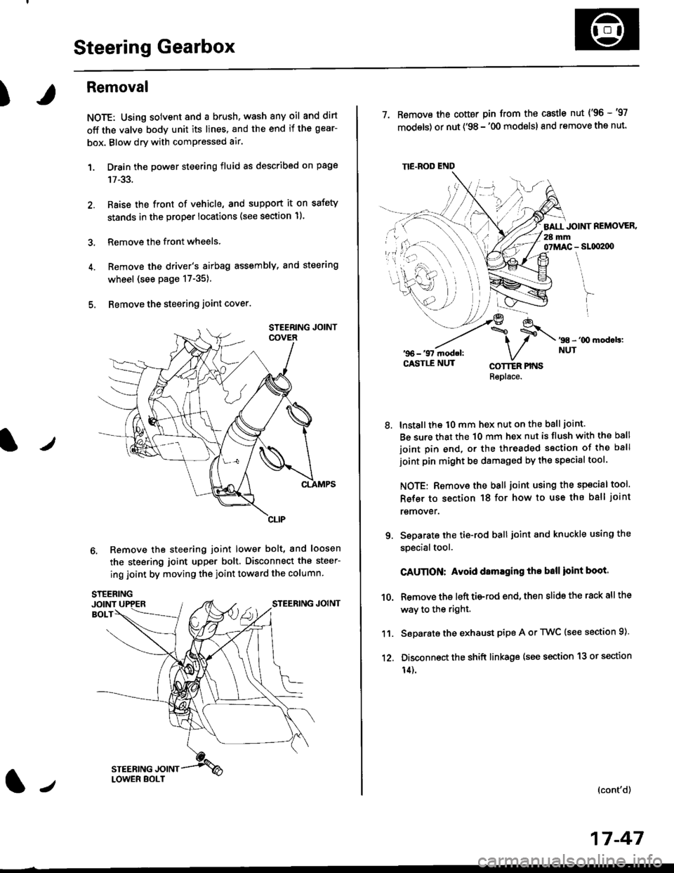
NOTE: Using solvent and a brush, wash any oil and dirt
off the valve body unit its lines. and the end if the gear-
box. Blow dry with comPressed air.
1. Drain the power steering fluid as described on page
2. Raise the front of vehicle, and support it on safety
stands in the proper locations (see section 11.
3, Remove the front wheels.
4. Remove the driver's airbag assembly, and steering
wheel (see page 17-35)
5. Bemove the steering joint cover.
6. Remove the steering joint lower bolt, and loosen
the steering joint upper bolt. Disconnect the steer-
ing joint by moving the ioint toward the column
tJ
17-47
TIE.ROD END
7. Remove the cotter pin from the castle nut {'96 -'97
models) or nut ('98 - '00 modslsl and remove the nut.
BALL JOINT REMOVER.28 mm07MAC - SLqI2|X)
'98 - '00 mod.b:NUT
8.
COTTER PINSRepl6ce.
lnstall the t0 mm hex nut on the ball joint.
Be sure that the 10 mm hex nut is flush with the ball
joint pin end, or the threaded section of the ball
joint pin might be damaged by the special tool.
NOTE: Remove the ball joint using the special tool.
Refer to section 18 for how to use ths ball joint
remover.
Seoarate the tie-rod ball joint and knuckle using the
specialtool.
CAUnON: Avoid damaging tho ball ioint boot.
Remove the left tie-rod end, then slide the rack all the
way to the right.
Separate the exhaust pipe A or TWC (see section 9).
Disconnect the shift linkage (see section 13 or section
14).
(cont'd)
9.
10.
11.
12.
Page 1105 of 2189
)
Disassembly
t)
Steering Rack DisassemblY
NOTE:
r Before disassemble the gearbox, wash it off with sol
vent and a brush.
. Do not dip seals and O-rings in solvent.
1. Remove the steering gearbox (see page 17-47]..
2. Remove the tie-rod end and locknut.
3. Remove air tube and cliPs.
Remove the boot bands and tie-rod clips Pull the
boots away from the ends of the gearbox.
BOOT
(|-,TIE.ROD CLIP
Hold the steering rack with a wrench ('98 -'00 mod-
els: left end only), and unscrew the rack end with
another wrench.
CAUTION: Be caroful not to damage the rack 3ur-
faco whh the wrench.
NOTE: '96 -'97 models is shown.
STEERING RACK END
STEERING RACK
Loosen the locknut, then remove the rack guide
screw and O-ring ('96 -'97 models only)
Remove the spring and the rack guide from the gear
housing.
7.
{cont'd}
17 -49
LOCK WASHER
Page 1120 of 2189
Steering Gearbox
Reassembly (cont'dl
64. Apply grease to the circumference of the rack endhousing.
RACK END GROOVE
=^.#-q!:s!!H
SILICONE GREASE
Apply a light coat of silicone grease to the bootgrooves on the rack ends.
lnstall the boots in the rack end with the tie-rodclips.
NOTE: Install the boots with the rack in the straightahead position (right and left tie-rods are equal inlength).
66.
RACK END
NOTE: Wipe the grease offthe thread section.
17-64
TIE.ROD CLIP
67. Adjust the air hose fitting position of the boots bvturning it as shown below.
LEFT BOOT(Viewed from theleft side)
RIGHT BOOT{Viewed from theright side)
AIR HOSE FITTING
Install new boot bands on the boot, and bend bothsets of locking tabs.
CAUTION: Stlke ths band locking tabs firmly.
Lightly tap on the doubled-over portions to reducetheir height.
Slide the rack right and left to be certain that theboots are not deformed or twisted.
Page 1121 of 2189
71.Connect the air tube between the right and left
boot.
lnstall the clips on the cylinder lines' then clamp the
air tube with the cliPs.
l./
CYLINDER LINE A
CLIP
l-,
lnstallation
CAUTION: Be carelul not to bend or damage the feed
line and cylinder lines when installing the gearbox'
1, Before installing the gearbox, slide the rack all the
way to right.
2. Install the mounting cushion on the steering gear-
DOX.
Install the pinion shaft grommet, then insert the pin-
ion shaft up through the bulkhead.
NOTE: Align the notch in the pinion shaft grommet
with the tab on the valve housing.
Install the mounting bracket over the mounttng
cushion, then installtwo gearbox mounting bolts'
MOUNTING BRACKET
cusHroN
39 N.m(4.0 kgj m, 29 lbtftlNOTE: Install the bracket
with the arrow Pornllngtoward the front.(cont'd)
17-65
Page 1129 of 2189

?
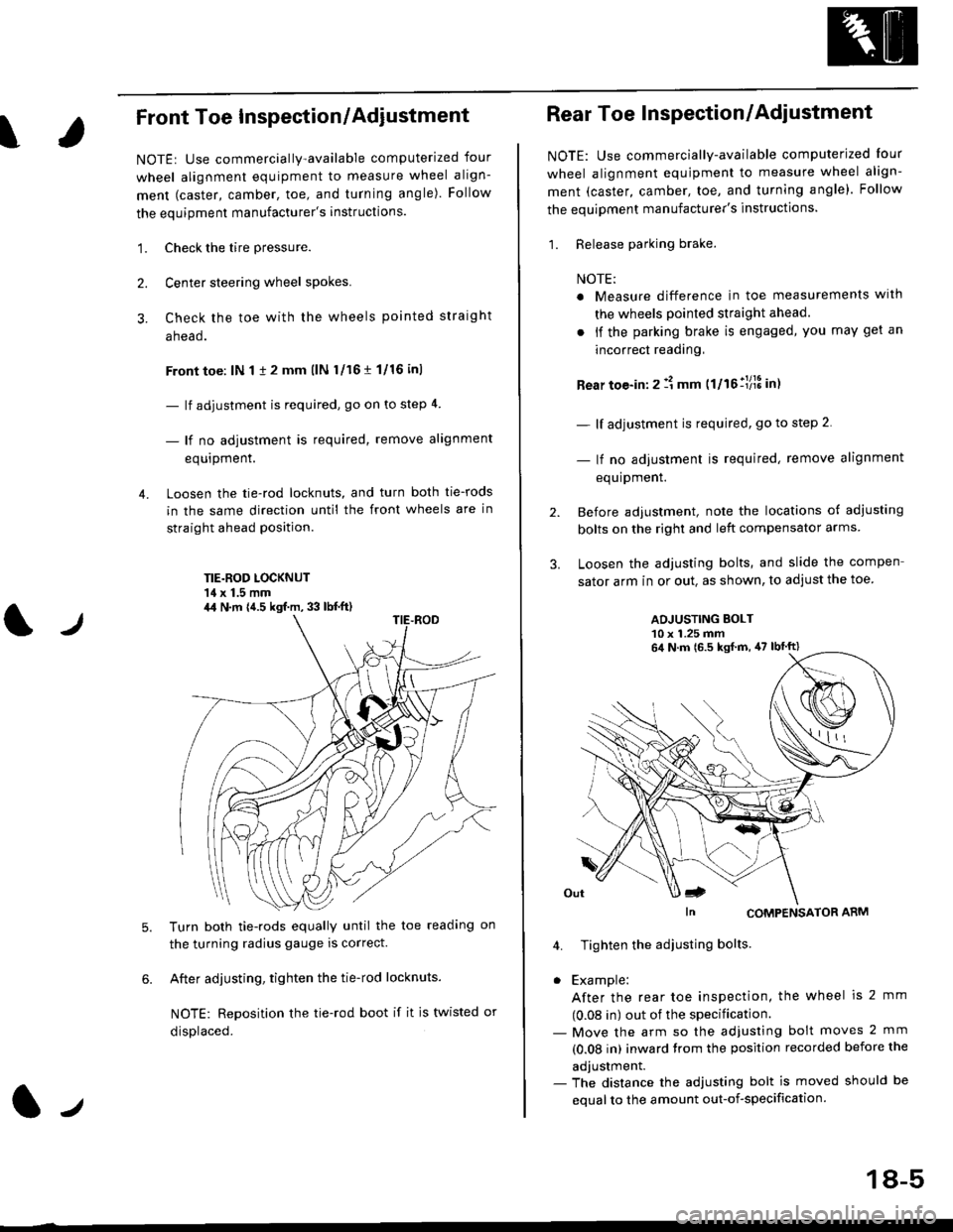
Front Toe Inspection/Adiustment
NOTE: Use commercially-available computerized four
wheel alignment equipment to measure wheel align-
ment (caster, camber, toe, and turning angle). Follow
the equipment manufacturer's instructions.
1. Check the tire pressure.
Center steering wheel spokes.
Check the toe with the wheels pointed straight
a head.
Front toe: lN 1 1 2 mm llN l/16 r 1/16 inl
- lf adjustment is required, go on to step 4.
- lf no adjustment is required, remove alignment
equrpmenr.
Loosen the tie-rod locknuts, and turn both tie-rods
in the same direction until the front wheels are in
straight ahead position.
TIE.ROD LOCKNUT'14 x 1.5 mm
4.
tJ
6.
Turn both tie-rods equally until the toe readang on
the turning radius gauge is correct.
After adjusting, tighten the tie-rod locknuts.
NOTE: Reposition the tie-rod boot if it is twisted or
displaced.
4,1 N.m {4.5 kgf.m, 33 lb{.ft)
2.
Rear Toe Inspection/Adiustment
NOTE: Use commercially-available computerjzed Iour
wheel alignment equjpment to measure wheel align-
ment (caster, camber, toe, and turning angle). Follow
the equipment manufacturer's instructions.
1. Release parking brake.
NOTE:
a Measure difference in toe measurements wlth
the wheels pointed straight ahead.
. if the parking brake is engaged, you may get an
incorrect readang,
Rear toe-in: 2 11 mm ttltollllS int
- lf adjustment is required, go to step 2.
- lf no adjustment is required, remove alignment
equipment.
Before adjustment, note the locations of adiusting
bolts on the right and left compensator arms
Loosen the adjusting bolts, and slide the compen
sator arm in or out. as shown, to adjust the toe
ADJUSTING BOLT10 x 1.25 mm
In CoMPENSAToR ARM
4. Tighten the adiusting bolts
. Example:
After the rear toe inspection, the wheel is 2 mm
(0.08 in) out of the specification.- Move the arm so the adjusfing bolt moves 2 mm
(0.08 in) inward trom the position recorded before the
adjustment.- The distance the adjusting bolt is moved should be
equal to the amount out-of-specification.
64 N.m 16.5 ksf m, 47 lbtft)
18-5